Thanks @NeverDie, I appreciate that.
Okay, well, the short answer to your question is yes, it’s a “linker directive” or rather a series of them, usually a file with the .ld extension. There’s normally a general stack/heap/etc. one called nrf_common.ld in Adafruit’s BSP, and then an architecture-specific one: nrf52.ld I think for the nRF52832 and nrf52840.ld for, well, I bet you can guess! ;)
This architecture-specific linker directive contains the memory locations for things like the MBR, ram region for the bootloader, initialized and (shared) non-init RAM, bootloader settings/configuration, MBR parameters, etc. The bootloader itself can of course read this memory allocation/settings/configuration data and then load any new application code or indeed new bootloader code wherever it needs to be. That’s why it’s best to let the bootloader perform the FOTA, either via serial or BLE.
Now I’m guessing here, but ideally, the arduino-NVM library that sort of emulates AVR EEPROM for MySensors could just read this information too and store it’s virtual EEPROM pages around these allocations. Currently, I think it just tries to determine the top application page address from the UICR and then allocate the pages based on that. It’s been a while since I looked at the code, so it might have changed. Essentially, it’s trying to find where the bootloader starts (if there is one) and allocate some pages a bit back from there to be safe.
In theory, a large enough application could overwrite this area - that’s why it’s not the best solution as I mentioned earlier - but if you reach that point, you’ve gotten so close to the bootloader with your application code, you might be in (other) trouble anyway! ;)
As far as a step-by-step with actual example code, demo files, etc. I’m more than happy to do it but it’ll take me some time. And would be helped if you could specify a particular board you’d like me to target (especially if I have one lying around), e.g. Nordic’s nRF52840 Dongle, Ebyte module, etc?
The other side of this is the FreeRTOS side. Would you like examples for the lowest possible power?
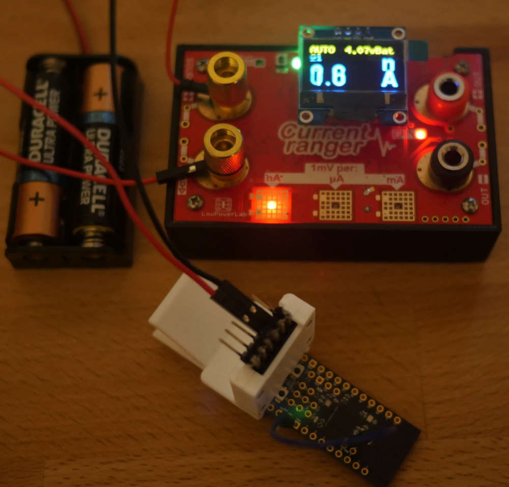
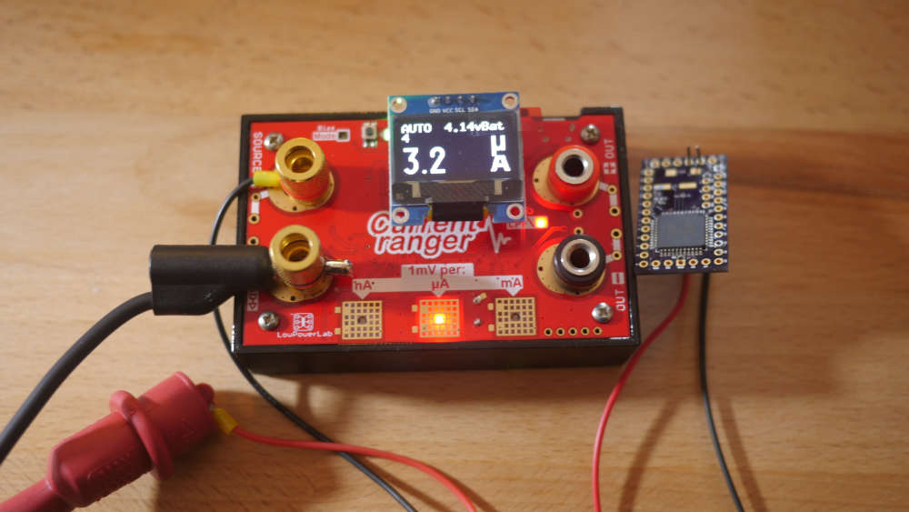
It seems like that’s how folk like these devices to operate. Going down around 2µA in bare System ON sleep (nRF52832) and around 300nA in bare System OFF sleep requires more involved MySensors code modifications, due to (among other things!) how FreeRTOS takes care of the power management when idling, use of the RTC(s), how it handles ISR callbacks, attaches interrupts, etc. By “bare” I mean no additional sensors, just, for example, a button or internal RTC (only in System ON) to wake it.
Does all, or at least some, of that make sense? :)