Skip to content
  • MySensors
  • OpenHardware.io
  • Categories
  • Recent
  • Tags
  • Popular
Skins
  • Light
  • Brite
  • Cerulean
  • Cosmo
  • Flatly
  • Journal
  • Litera
  • Lumen
  • Lux
  • Materia
  • Minty
  • Morph
  • Pulse
  • Sandstone
  • Simplex
  • Sketchy
  • Spacelab
  • United
  • Yeti
  • Zephyr
  • Dark
  • Cyborg
  • Darkly
  • Quartz
  • Slate
  • Solar
  • Superhero
  • Vapor

  • Default (No Skin)
  • No Skin
Collapse
Brand Logo
andrewA

andrew

@andrew
About
Posts
126
Topics
2
Shares
0
Groups
0
Followers
3
Following
0

Posts

Recent Best Controversial

  • CNC PCB milling
    andrewA andrew

    @andrew Important to note, that I'm still talking about hobby cnc solutions. For professional CNC working and for a pro machine I'd prefer to use as many "pro" and automated solutions as possible.
    for occasional hobby purposes defined in this thread, and for these damn cheap machines I think it does not make sense.

    pro machines with auto tool change do benefit from auto probing, but that is a total different story.

    General Discussion

  • CNC PCB milling
    andrewA andrew

    @NeverDie : well,

    • for PCB milling this spring loaded stuff simply does not work, as the whole area should be mapped.
    • for non-PCB Z zeroing it could be good, however in such case (imho) this is just an over complicated/engineered method for a simple probing.

    when you need a single z touch levelling then better to have a rock solid solution rather then have additional moving parts and potential other vectors for a failure. even with a slow feed rate, a single probe can be done in an acceptable time period, so why should you risk your result?
    I can imagine that this spring stuff can help you when you approaching with quite high feed rate for first, but in such case I would be afraid of the "wearing" of the probe surface over time and the inaccuracy it may cause later on.

    btw, the "double probing" with fast then a slower feed rate is used by other sw/firmware, e.g. marlin does the same (in certain configurations) for 3d printers.

    General Discussion

  • CNC PCB milling
    andrewA andrew

    @NeverDie after changing the tool I always make a single touch probe so Z level can be adjusted to the new tool properly.

    This is necessary even for the PCB milling. After the levelling is done, a single touch probe is needed somewhere in the working are to set the Z0 and to make it as a reference point for the bed levelling mesh.
    At least this is how it is done in bCNC.
    After the isolation routing is done, I make a single Z touch probe for each drill bits to set the correct Z0 for the given bit. This is done in the same way as in case for the PCB probing.
    Note that as the drilling on Z axis does not require high precision (basically if your drilling depth is slightly bigger than the PCB thickness, then even if your Z is just roughly adjusted to the PCB top, it will do the job).

    As I currently work with PCBs only, no other touch probe was necessary, however for woodworking (or for other non conductive materials) one can use a dedicated "touch probe".

    There are nice solutions form a simple PCB:
    https://www.youtube.com/watch?v=l9o6ZUjb3k0&ab_channel=NikodemBartnik

    or
    https://www.youtube.com/watch?v=58m1v-fHFjU&ab_channel=CosmoChannel

    or you can buy a cheap touch probe as well:
    https://www.aliexpress.com/item/4001010640247.html

    or you can go for nicer and more expensive professional touch probes :)

    General Discussion

  • CNC PCB milling
    andrewA andrew

    I had a chance (and a need) to make a quick PCB prototype again, so I've finished my first real-life exercise with my new CNC3020(T).

    I made two mistakes:

    • as I was in hurry, I did not use enough measurement points for the levelling. A small extra copper remained at two places, hopefully it won't need too much work to get rid of it. The time saved on the levelling will be spent twice on the post-processing... lesson learned... again...
    • I made an unintended short during the levelling and had to reset the controller. Working coordinates were re-defined manually, causing a small shift between the two sides. Once I'll have my new controller ready, this should not happen again.

    Beside these issues, the result still looks amazing.
    Here are some pictures for reference:

    20201106_200847.jpg

    20201106_202113.jpg

    20201106_210426.jpg

    20201106_210444.jpg

    20201106_224057.jpg

    isolation:
    https://youtu.be/7kZHOMzWgUI

    drilling:
    https://youtu.be/kUqxxttMfyc

    Conclusion: CNC2030T is an affordable CNC machine which can be easily used for precise PCB prototyping.
    Btw, this was my conclusion for my previous CNC2418 as well. Both of them proved their capabilities. CNC3020T is just better, more robust and good for more stuff.

    To be honest, if one buys a CNC from the super cheap 2418 category and the main goals is PCB milling/drilling, then I do not see any reason to spend money and time on upgrades, as the base machine is good for the job.

    General Discussion

  • CNC PCB milling
    andrewA andrew

    @andrew oh, for those who are interested, flatcam settings were the followings:

    • tool dia: 0.1176326981
    • passes: 2
    • overlap: 0.15
    • cut z: -0.05
    • feed rate: 500
    • spindle: 300 (0-1000 range, but in fact as the pwm signal is inverted now, it is equivalent with 700)

    the engraving tip was 2001 (20degree, 0.1mm end)

    General Discussion

  • CNC PCB milling
    andrewA andrew

    quick update, just managed to make some test milling.
    pro tip: always check your tip before milling :) I had to trash the one I used for the first two, as its end was chipped

    traces are 6 mil, the footprint is tqfp100 p0.5, built in from kicad.
    some of the the standalone traces are 6 mil with 6 mil clearance, their open end came up, but otherwise it looks ok.

    other 6 mil traces that are connected to pads are actually ok.

    6mil traces where the clearance is 4 mil only were not millet at all, due to the isolation routing path made by flatcam.

    overall, I'm happy with it.

    I've also ordered a dial indicator measurement tool, I'll report the backlash and other measured precision details when it arrives.

    some pics:
    the control box is open and it has an additional external grbl controller now, I'm working on a proper electronics.
    small_20201010_091550.jpg

    small_20201010_100008.jpg small_20201010_095958.jpg

    small_20201010_100018.jpg

    small_20201010_100409.jpg

    General Discussion

  • CNC PCB milling
    andrewA andrew

    @niallain it is 3020T which uses trapezoidal screws. "Z" uses ball screws.
    you can check the "official" technical details on the item's specification (scroll down to the description then click on the "specification"):

    ...
    Driving units X axis: 1204 trapezoidal screws
    Driving units Y axis: 1204 trapezoidal screws
    Driving units Z axis: 1204 trapezoidal screws
    ...
    Repeat accuracy: 0.05mm
    ...
    Spindle precision: radial beat acuities 0.03 mm
    ...

    Note that none of these parameters above are confirmed. To be honest I don't have the right measurement tools for that, but the fine trace PCB samples will prove it, or not :)

    General Discussion

  • CNC PCB milling
    andrewA andrew

    @NeverDie it is a knob for manual positioning. the whole assembly and machine is very massive and stable, all metal parts do matter a lot.

    General Discussion

  • CNC PCB milling
    andrewA andrew

    @mlei30 This was my choice:
    https://www.ebay.com/itm/CNC-Router-3020T-3-AXIS-USB-Graviermaschine-GraviergeräT-FräSmaschine/313030564524
    It already arrived and I started to play with it.
    I decided not use its Chinese controller software or Mach3 with parallel port connection, so it needs some upgrade before I can make the first tests with it.
    There are tons of upgrade options to make it work with open source stuff. I almost ordered a TinyGv2 controller, but it turned out, that that CNC can be GRBL controlled over the parallel port. In such case,
    original stepper and spindle drivers can be used as well.

    The problem is, that the research I found behind this was misleading and it contains inaccurate / improper details (or at least not exactly applicable to my HW version), so I had to re-execute the reverse engineering.

    I'm about to finish it. At the moment I can control everything on the CNC from GRBL. Now I need to calibrate it and make the solution "solid/proper". I have hard time finding free time for this, but I hope that first test runs will be done soon.

    I'll be back with the results soon (and I'm also planning to write a blogpost on the details later).

    General Discussion

  • CNC PCB milling
    andrewA andrew

    @NeverDie sure, you will hear more about my new gear :)
    Considering the shipping time and my availability, this should happen around late August or early September!

    General Discussion

  • CNC PCB milling
    andrewA andrew

    Hey @NeverDie, everyone,

    It is good to see how this thread developed over the time and you guys are enjoying the PCB milling.
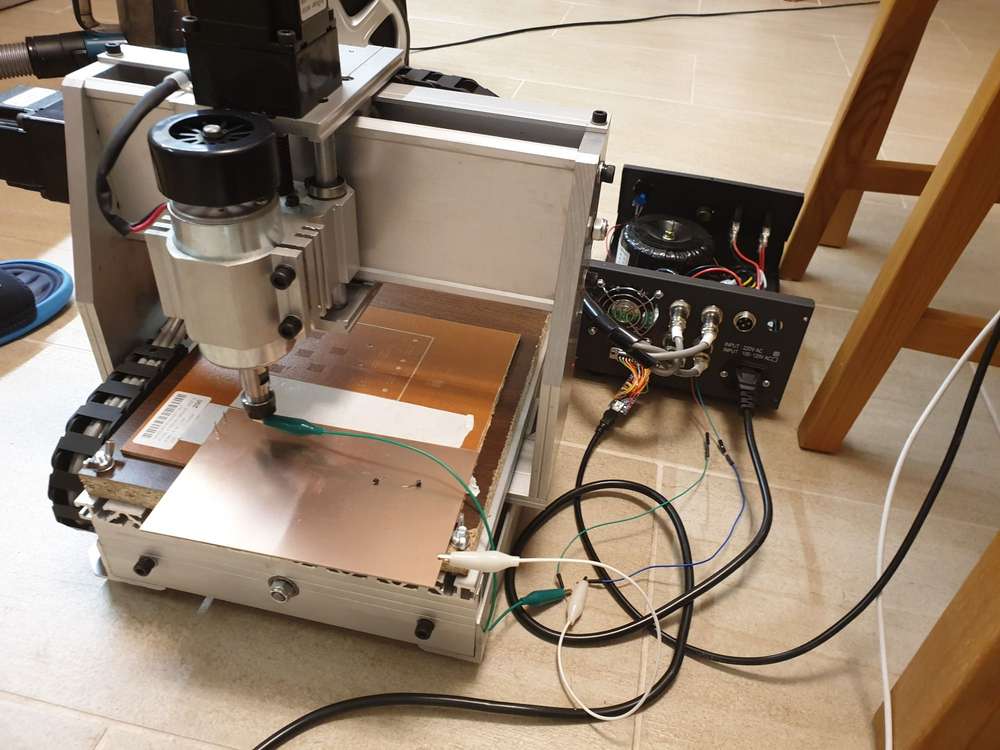
    Unfortunately I had many other responsibilities and was super busy, so a lot from my projects had to be postponed. Nevertheless I'm still working with my CNC.

    A few days ago I replaced the spindle to a laser module to make same plywood engraving, and the original spindle motor holder (the 3D printed stuff) broke during the unscrew...

    small_20200807_085807.jpg

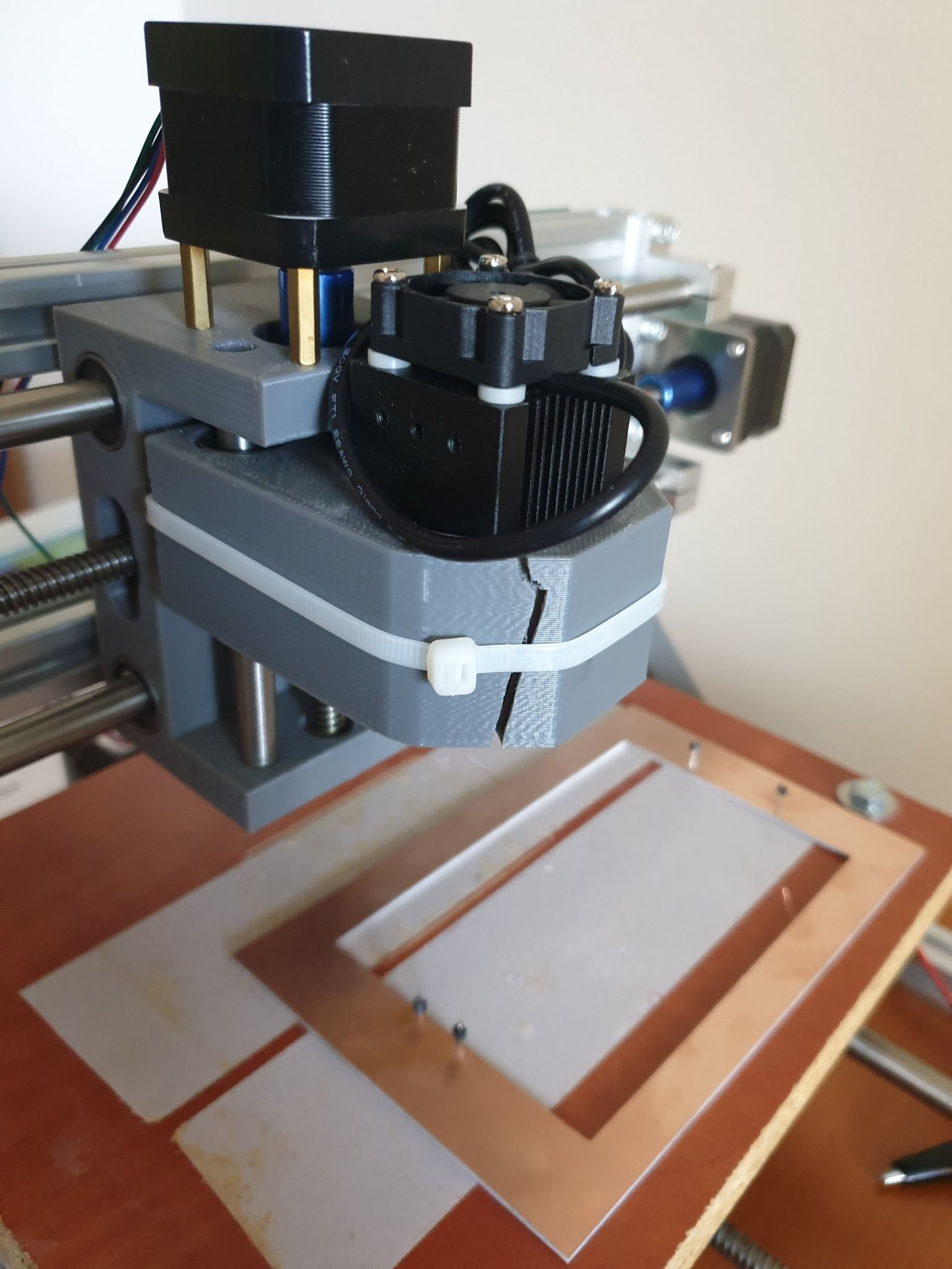
    I managed to fix the laser module with cable tie. :)
    It is ok for the laser, but of course not for the spindle and for the PCB milling.
    Replacement parts are available mostly in packages (e.g. https://www.ebay.com/itm/Replacement-Parts-DIY-Kit-for-CNC-1610-2418-3018-Spindle-Holder-Screw-Polish-Pod/112382449851), but it is possible to print your own version too.
    Some guys already came up with an enhanced design, such as https://www.thingiverse.com/thing:3586273

    I already wanted to make an upgrade on the CNC, so I came to a conclusion, that I will fix the broken part with a custom 3D printed one, then sell the machine.

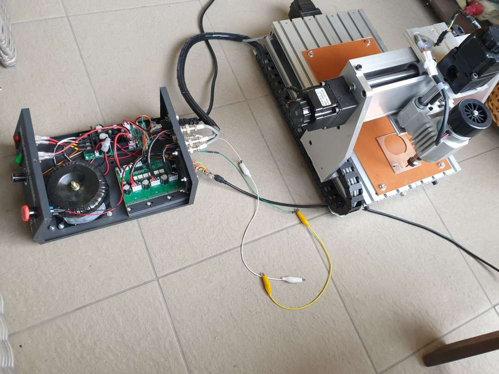
    I already ordered my new toy, a CNC3020T (EUR 325 + shipping EUR 25):

    cnc3020t.jpg

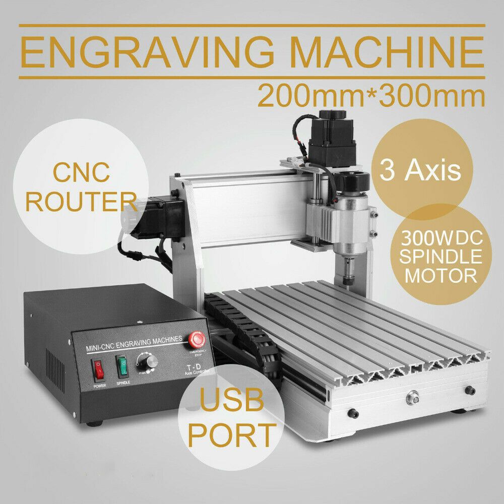
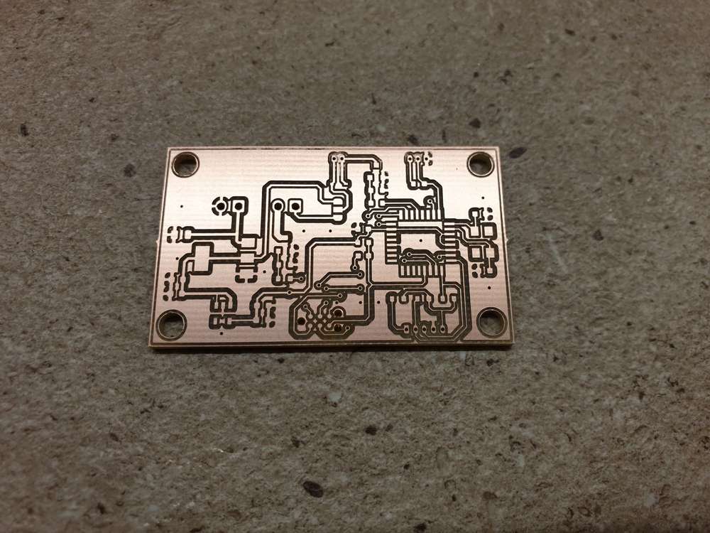
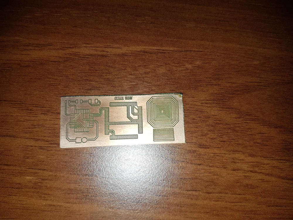
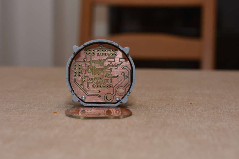
    Well, I hesitated a lot and almost bought a CNC3040Z-DQ (bigger, better, ball screw), but as currently I really don't have enough space for it (and to be honest, no reason to buy a better/bigger) I sticked with the 3020T. The quality I achieved with my 2418 will be definitely reproducible and this is enough.

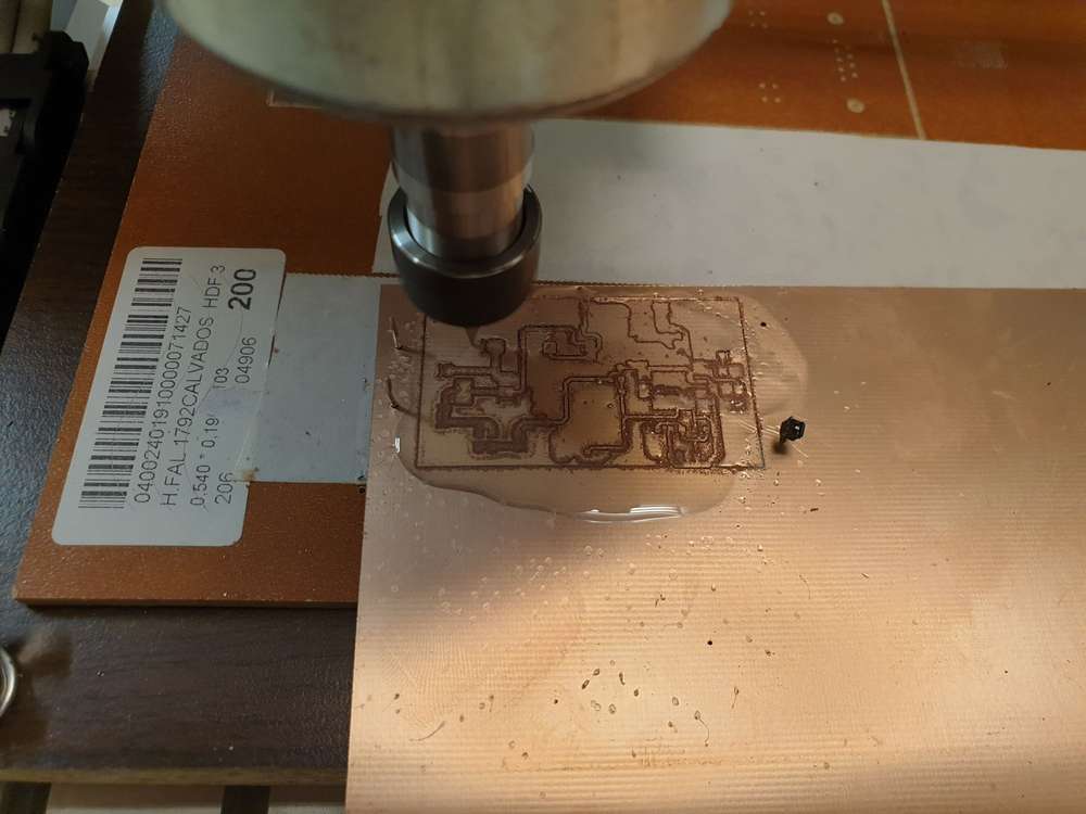
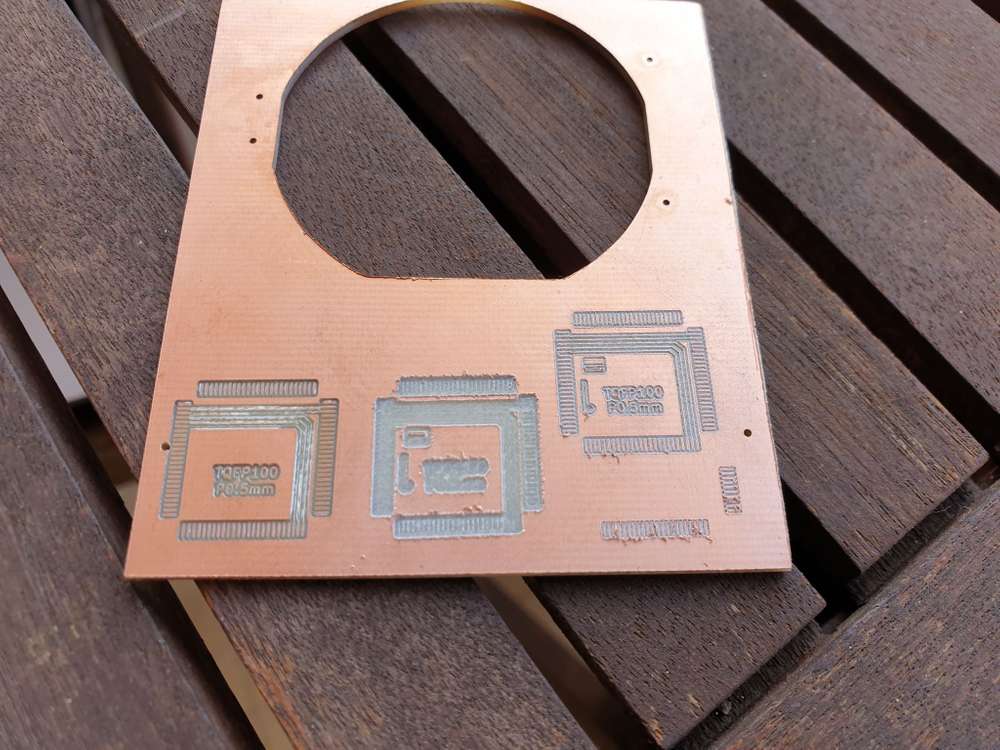
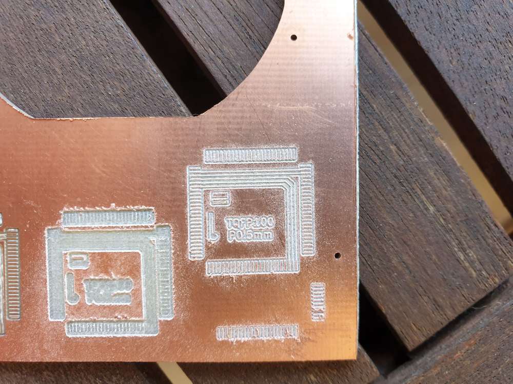
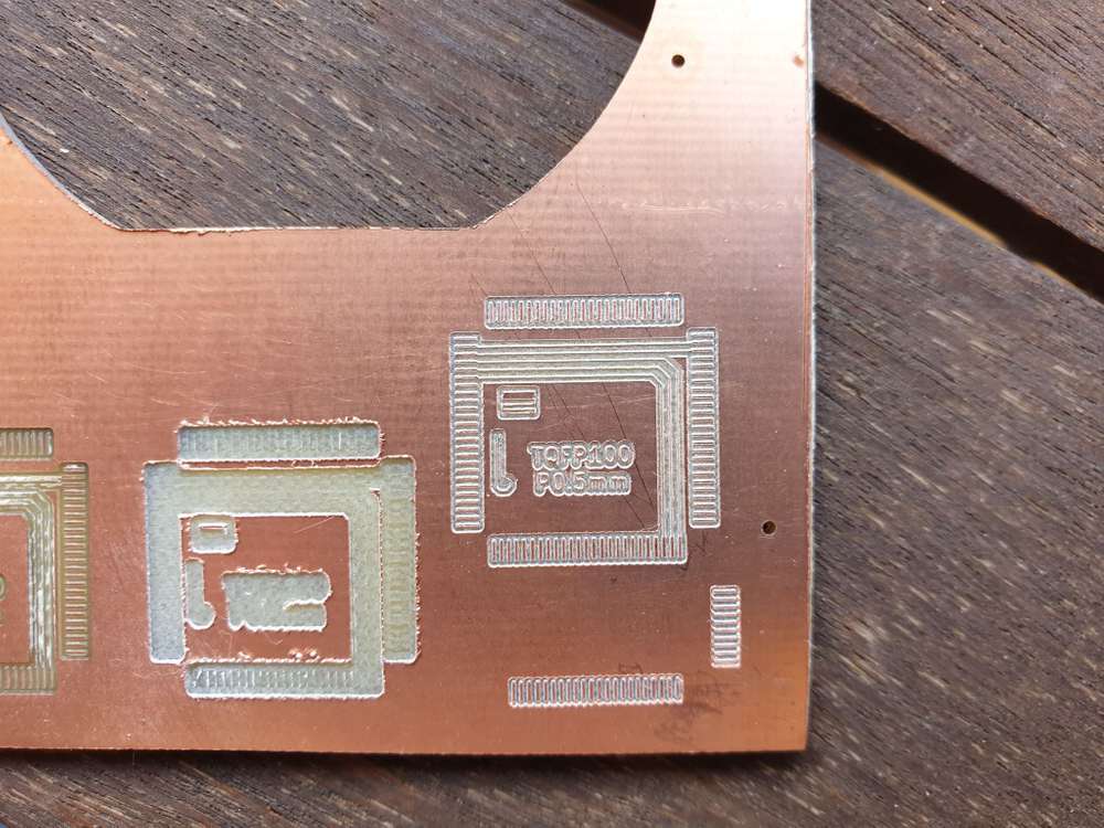
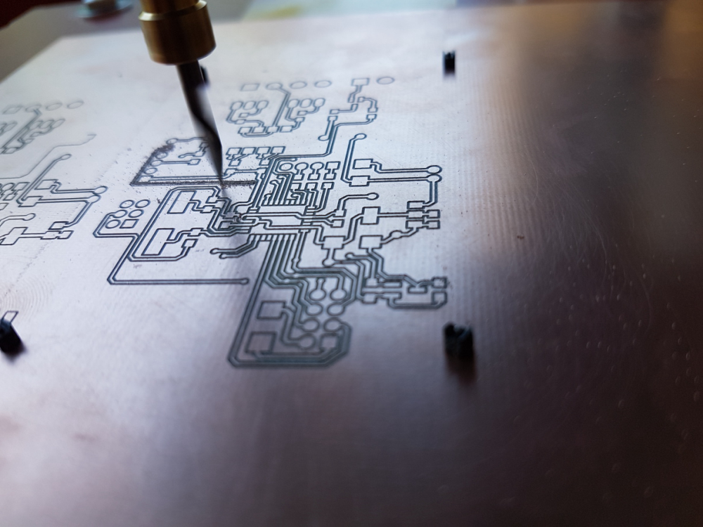
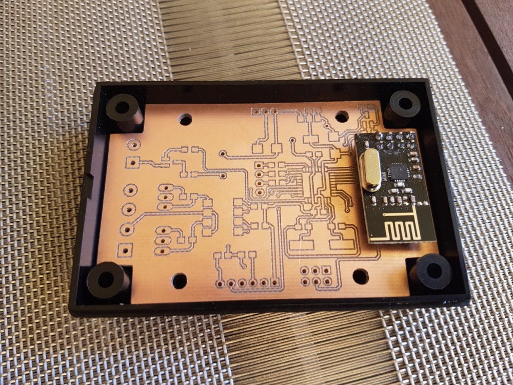
    I just read the endmill isolation routing posts. Interesting stuff.
    I'm curious whether you can use smaller ones to deal with the 6mil/6mil trace/isolation sizes.

    Happy milling and cheers!

    General Discussion

  • CNC PCB milling
    andrewA andrew

    @lamikr pls see one of my very first test I made after I built my cnc. check the TQFP100 footprint.

    for me, the cnc2418 was good choice. with proper assembly it is very stable and its output is stable.
    I was using the cnc for designs down to 10mil traces without any issue.

    so, I have good experience with my low cost cnc but do to the lack of hands-on experience with other devices, I cannot compare or recommend others.

    0_1548754957612_small_20171101_210626.jpg

    1_1548755165291_small_20171119_164624.jpg

    0_1548755165290_small_20171119_163603.jpg

    General Discussion

  • What did you build today (Pictures) ?
    andrewA andrew

    @jeremushka I reused the top PCB (the touch panel) with its original microcontroller, but with a custom firmware. the bottom PCB was fully replaced with my own designed version. this includes the power supply with additional protections, atmega328, atsha and nrf radio.
    it is running very well on my desk, but I was super busy in the past months so it is not yet installed to the wall.

    in parallel I also had to finish its opposite side, the controller at the lamp. it is also ready for final installation, I just need time for that :)

    0_1530125916809_small_20180525_113929.jpg

    0_1530125929873_small_20180525_182927.jpg

    0_1530125937823_small_20180525_183020.jpg

    0_1530125944916_small_20180611_102114.jpg

    General Discussion

  • CNC PCB milling
    andrewA andrew

    @neverdie the controller does not limit it, but the firmware settings. however, based on my default settings the feedrate is limited (by config) to 800. check your $110, $111, and $112 config options.
    https://github.com/gnea/grbl/wiki/Grbl-v1.1-Configuration#110-111-and-112--xyz-max-rate-mmmin

    you are free to override this configuration with a different value, so you can try 1400 in the grbl firmware settings, which will cause real 1400 feed rate in case of you test G code.
    the questions is that how the steppers/spindle could handle this.

    General Discussion

  • CNC PCB milling
    andrewA andrew

    @neverdie what was the cost for the overall upgrade?

    for me the 10 mil traces also worked with the default sw/hw configuration.

    did you change any parameter in the grbl firmware? 1400 feedrate is very nice, much faster than mine, however I did not use higher rates than 200 so far.

    your steppers are still the same? is it ok for the high feedrate without any issue?

    General Discussion

  • CNC PCB milling
    andrewA andrew

    hello everyone,

    what is the current status with the quality, fine traces and result stability?
    after a long absence I finally had some time to finish my new board and prototype it.
    I don't have those issues that appearing for some of you, the result is pretty nice, the milling quality is the same across the whole board.
    in this design the thinnest traces were 15mils, and the smallest vias were 0.8mm with 0.3mm drilled holes.

    0_1527023946011_small_20180521_092313.jpg

    1_1527023946013_small_20180521_101938.jpg

    2_1527023946014_small_20180521_102134.jpg

    3_1527023946014_small_20180521_124252.jpg

    just for reference, please see my relevant configuration options detailed below:

    tools

    • cnc: cnc2418
    • carving: 2001 bit (20 degree, 0.1mm end)
    • mounting holes and outline milling: 0.8mm endmill

    config

    • isolation routing: tool dia: 0.1176326981mm; width (# passes): 2; pass overlap: 0.05mm; cut-z: -0.05mm; feed rate: 200
    • milling: tool dia: 0.8mm; cut-z: -1.75mm; feed rate: 170; depth / pass: 0.3mm
    • drilling: feed rate: 120

    software:

    • flatcam
    • bcnc (also for the autoleveling)
    General Discussion

  • nRF5 OTA updates
    andrewA andrew

    I just started to review the NRF5* possibilities. regarding to the code protection, are you sure that you have to implement this by your own?
    what do you think about CTRL-AP - Control Access Port, APPROTECT?

    http://infocenter.nordicsemi.com/index.jsp?topic=%2Fcom.nordic.infocenter.nrf52832.ps.v1.1%2Fdif.html&anchor=concept_udr_mns_1s

    Development

  • CNC PCB milling
    andrewA andrew

    @neverdie said in CNC PCB milling:

    What's the best type of sacrifice board to use if doing bed flattening? Regular wood, or should I stick with particle board or MDF?

    I never had to try it, so I don't know. for me the regular wood seems to be logical...

    General Discussion

  • CNC PCB milling
    andrewA andrew

    @neverdie for pcb milling a small height difference across the board's area could result in a big negative effect if autoleveling is not performed properly.
    I would double check your autoleveling process, on the other hand, you could also try to use bed flattening with a bigger endmill tool first, then place the pcb to the flattened area. this could help you to eliminate or decrease the cnc assembly or the sacrificial board caused roughness.

    for further details please see the following link:
    http://flatcam.org/manual/procedures.html#bed-flattening

    General Discussion

  • CNC PCB milling
    andrewA andrew

    @neverdie said in CNC PCB milling:

    I drilled the alignment holes with 0.8mm diameter. I'm using regular male header pins for the alignment, and having tried it, I think 0.8mm is really too tight. Not sure how @andrew is using 0.7mm. Different pins I guess? Anyhow, next time I'll try 0.9mm hole diameter.

    maybe my pins also have different factors, but indeed, the given holes are pretty tight. this helps to prevent unnecessary pcb movements, which is very important if you work with 6mil traces/isolation, as a small unwanted movement could result in wasted pcb. if you work with bigger traces/clearings then it is not as important.

    I would recommend to stick to one size which is good for your selected pins and which does not let the pcb to move.

    General Discussion
  • Login

  • Don't have an account? Register

  • Login or register to search.
  • First post
    Last post
0
  • MySensors
  • OpenHardware.io
  • Categories
  • Recent
  • Tags
  • Popular