Navigation

    • Register
    • Login
    • OpenHardware.io
    • Categories
    • Recent
    • Tags
    • Popular
    1. Home
    2. andrew
    3. Best
    • Profile
    • Following
    • Followers
    • Topics
    • Posts
    • Best
    • Groups

    Best posts made by andrew

    • RE: What did you build today (Pictures) ?

      @andrew said in What did you build today (Pictures) ?:

      0_1512830079874_small_20171119_155404.jpg 0_1512830092134_small_20171119_163354.jpg 0_1512830107562_small_20171119_163849.jpg 0_1512830119867_small_20171119_164745.jpg 0_1512830130032_small_20171119_165717.jpg 0_1512830150237_small_20171203_092353.jpg 0_1512830159490_small_20171203_163658.jpg 0_1512830169403_small_20171207_194213.jpg

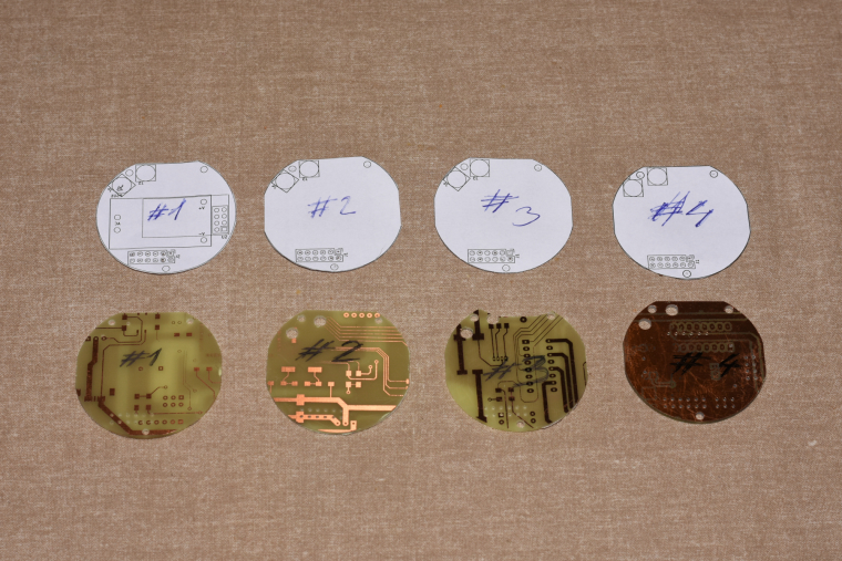
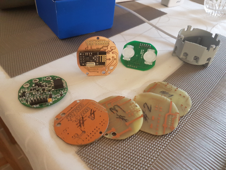
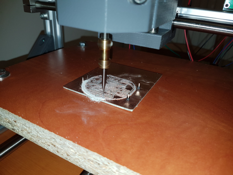
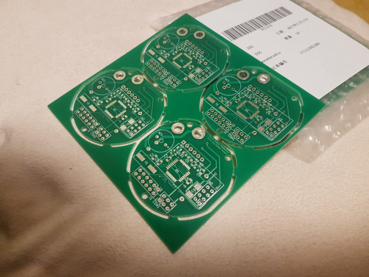
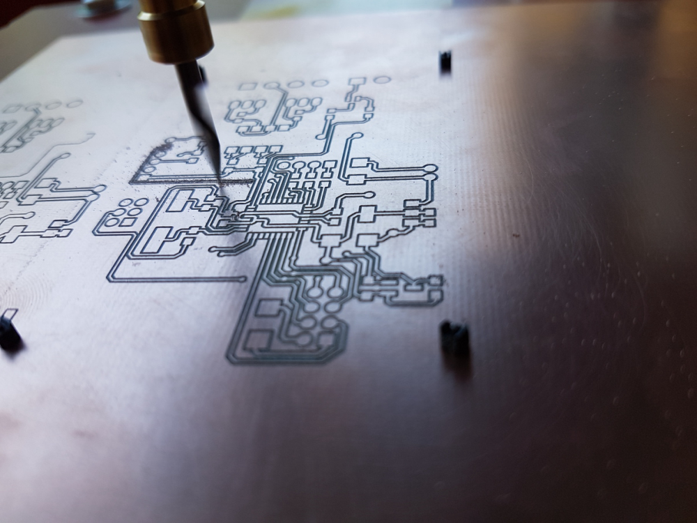
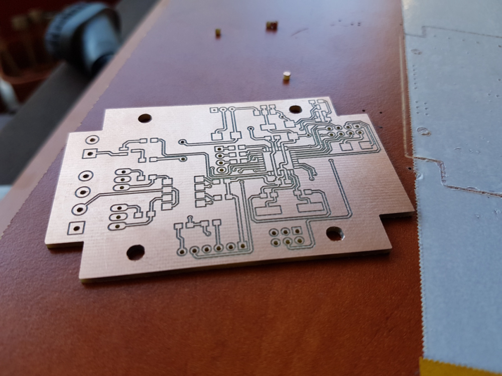
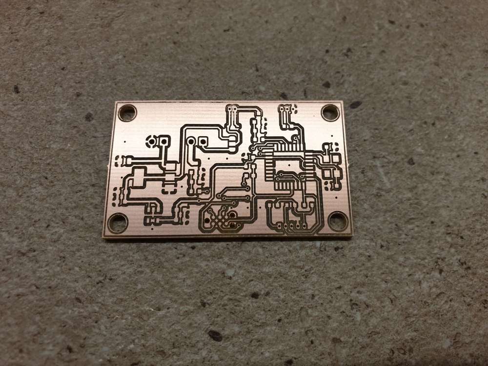
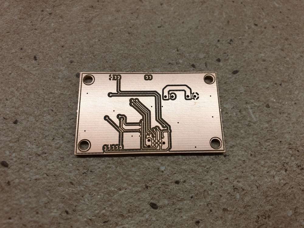
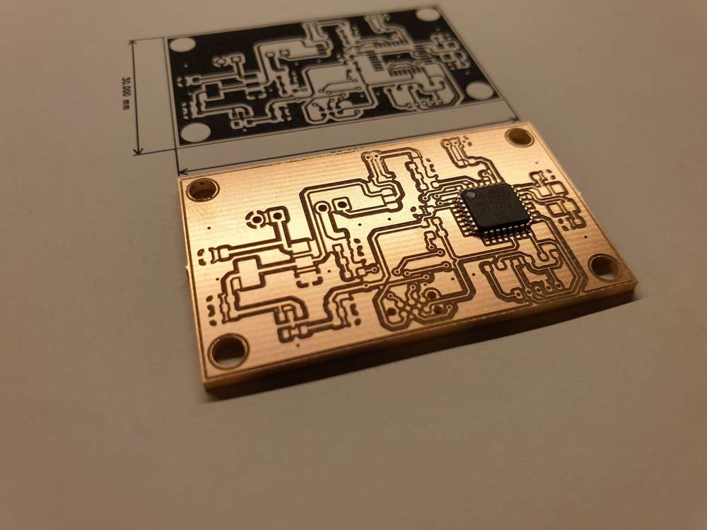
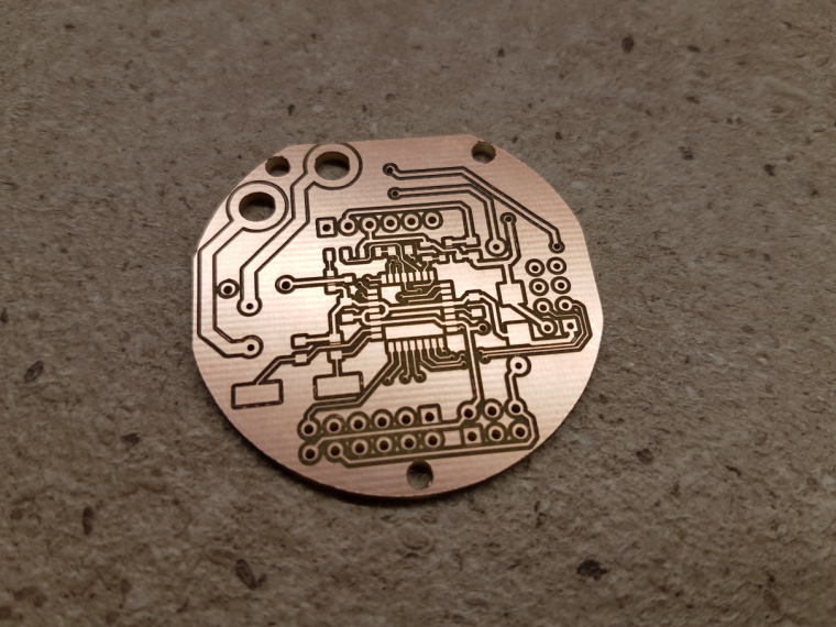
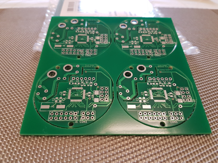
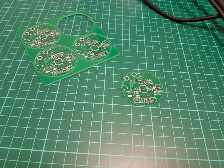
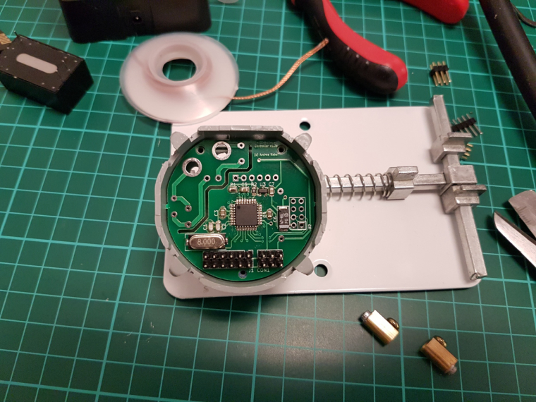
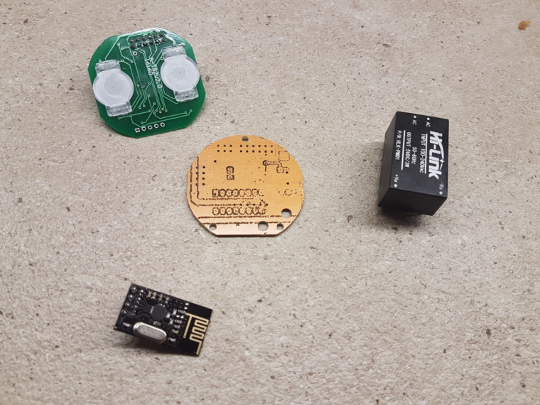
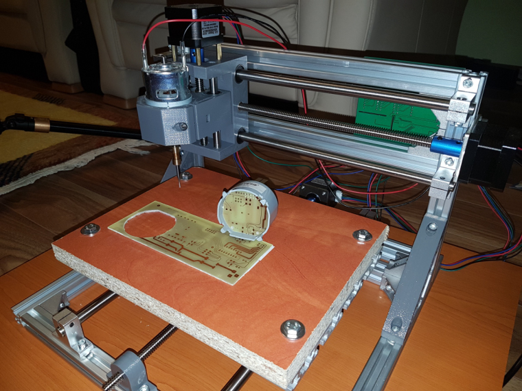
      so, it is ready. I mean ready to SW development πŸ™‚ both the schematic and pcb design is now confirmed and fortunately theory meets the practice πŸ™‚

      0_1515090568483_small_small_20180103_235320.jpg

      0_1515090578447_small_small_20180104_001658.jpg

      0_1515090588886_small_small_20180104_003546.jpg

      0_1515090603769_small_small_20180104_003556.jpg

      0_1515090626947_small_small_20180104_004540.jpg

      0_1515090649476_small_small_20180104_004605.jpg

      0_1515090667193_small_small_20180104_004655.jpg

      0_1515090681698_small_small_20180104_005413.jpg

      0_1515090695413_small_small_20180104_005424.jpg

      0_1515090706426_small_small_20180104_010443.jpg

      0_1515090717200_small_small_20180104_010955.jpg

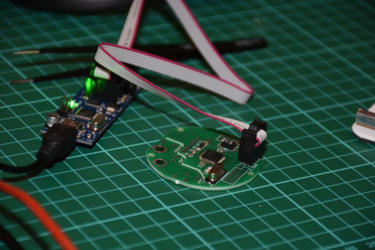
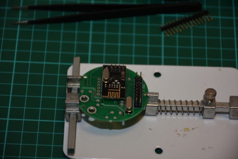
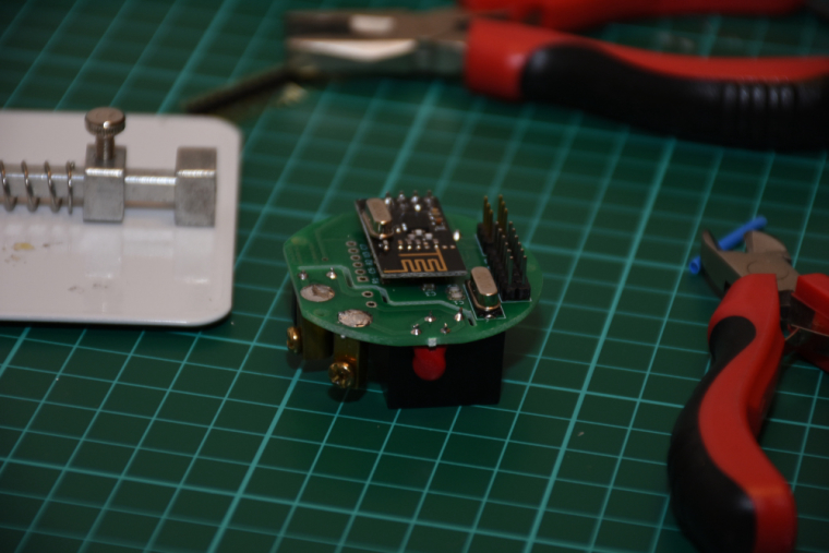
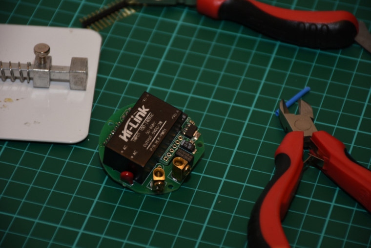
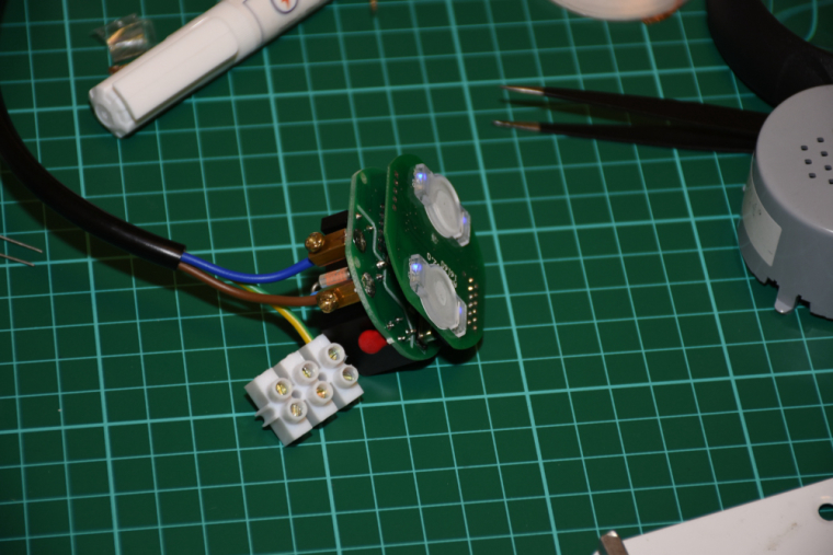
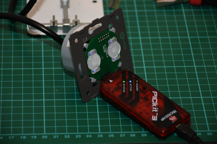
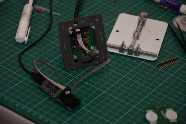
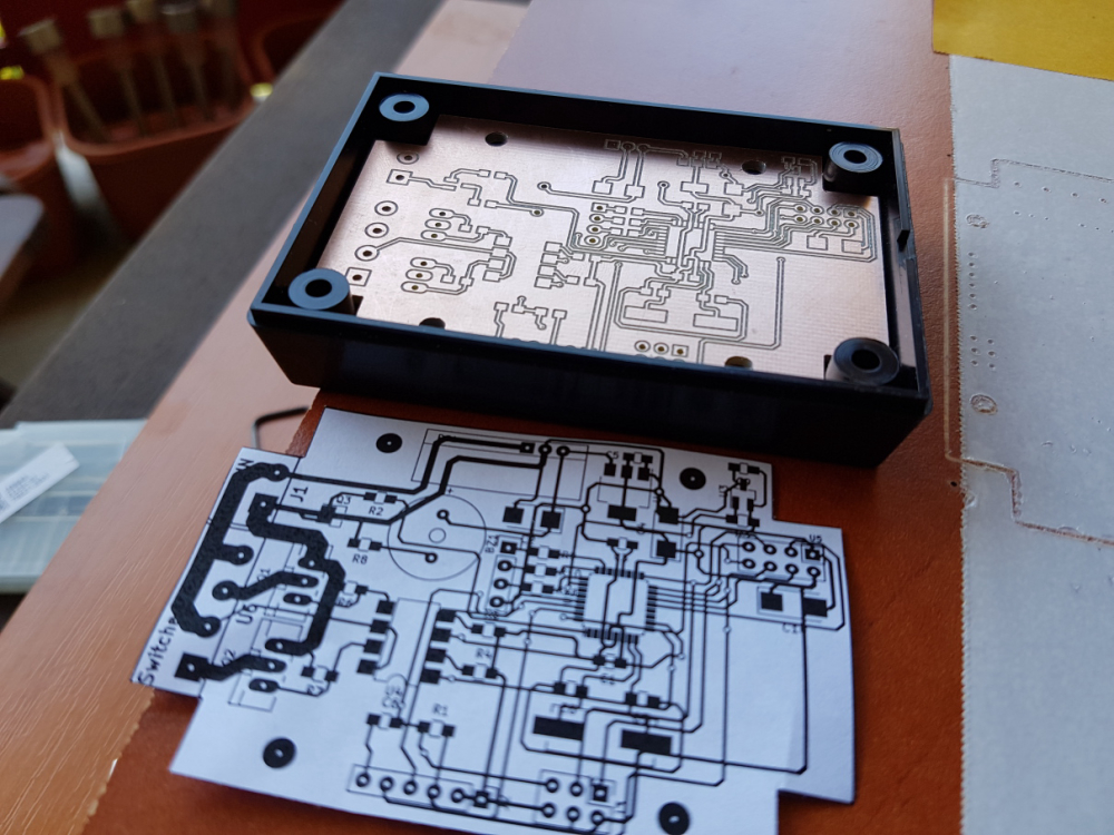
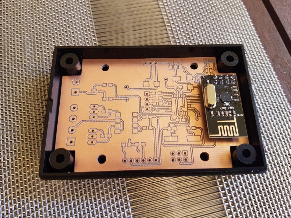
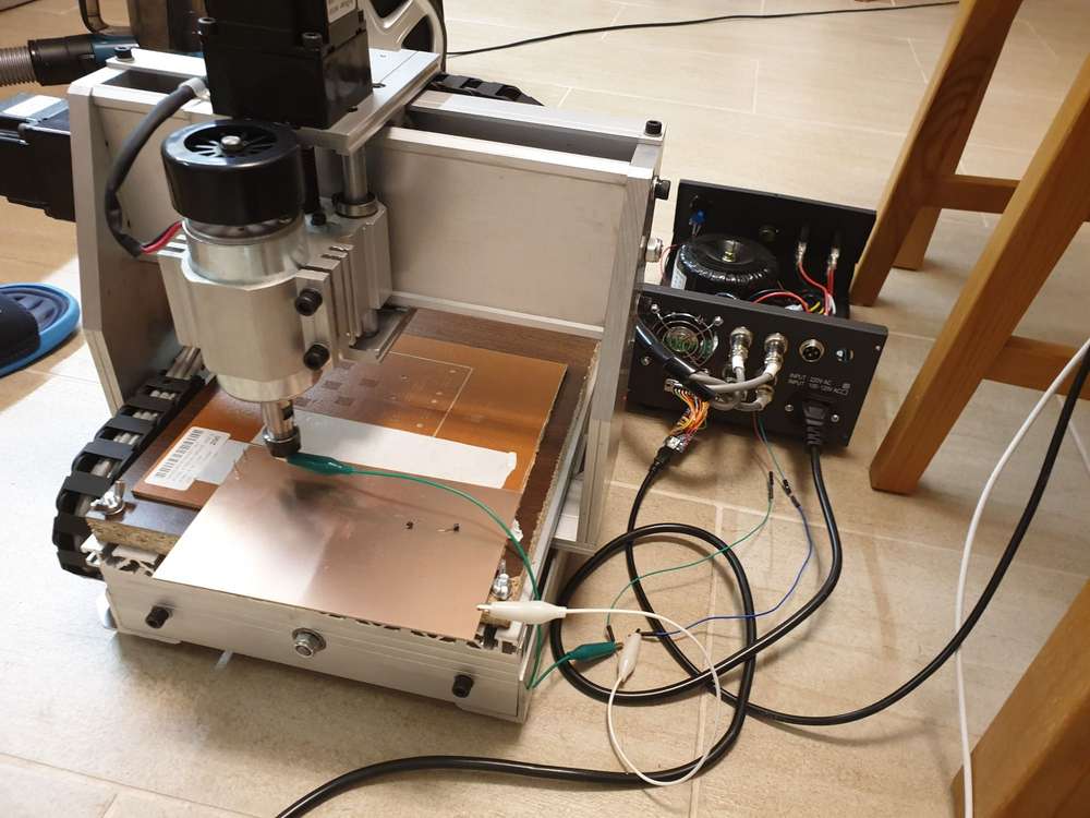
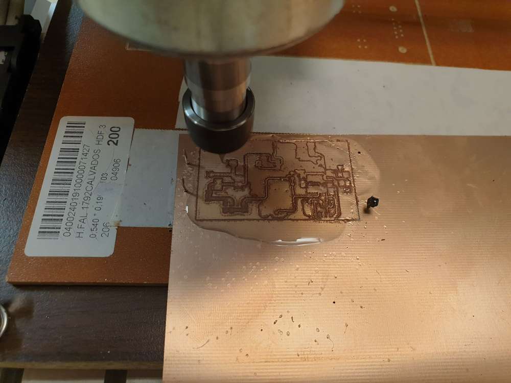
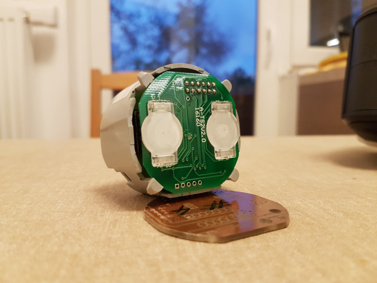
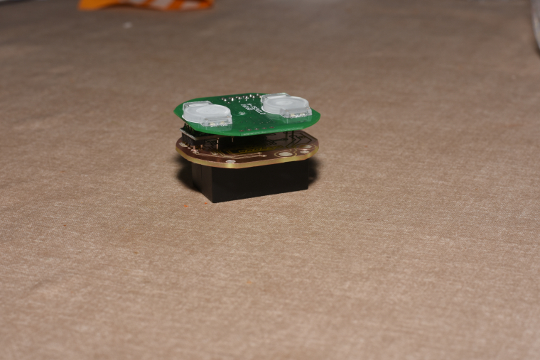
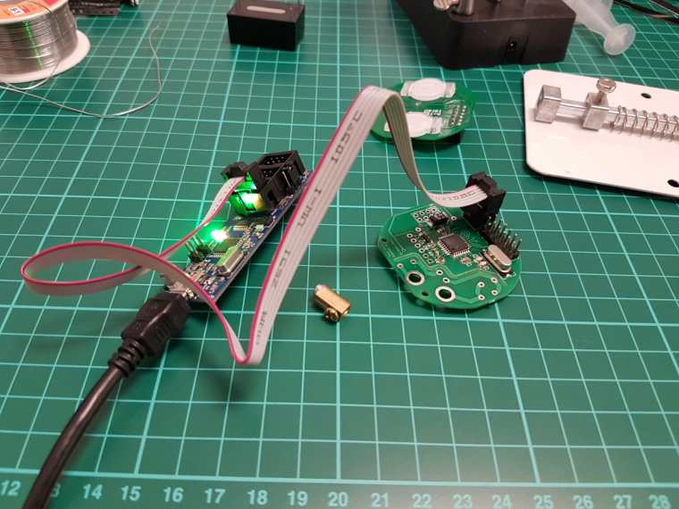
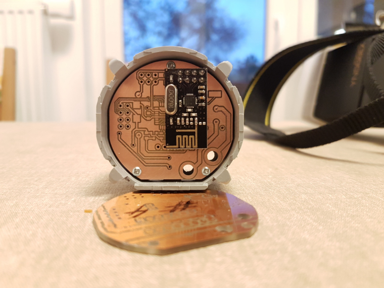
      it is assembled, programmed, tested, everything works as expected.
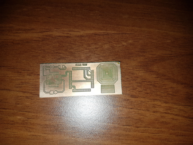
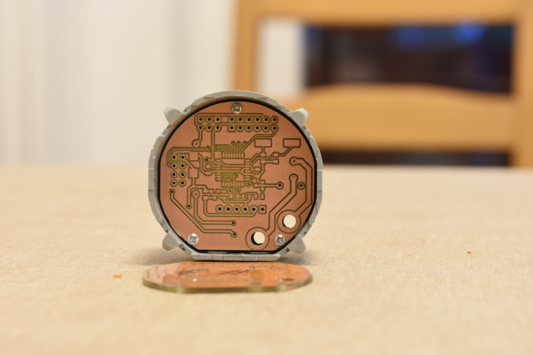
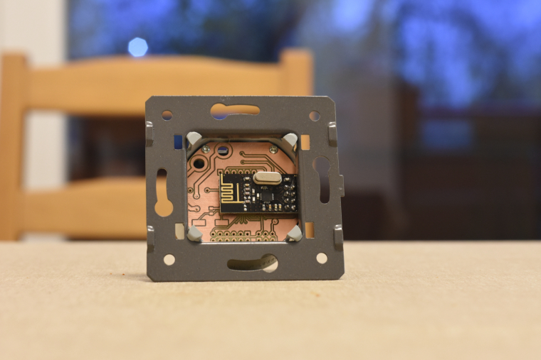
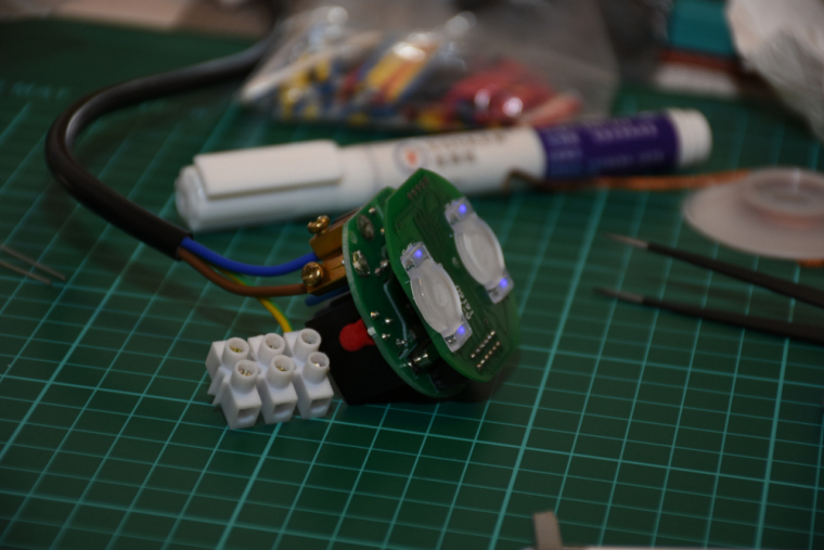
      I did not mount it to the wall so far (I'll need a controller and real actuators first), but there was no issue with the communication between two nrf modules (both with PCB antenna) from cca 6 meter distance + 2 walls (10 cm brick) in between.

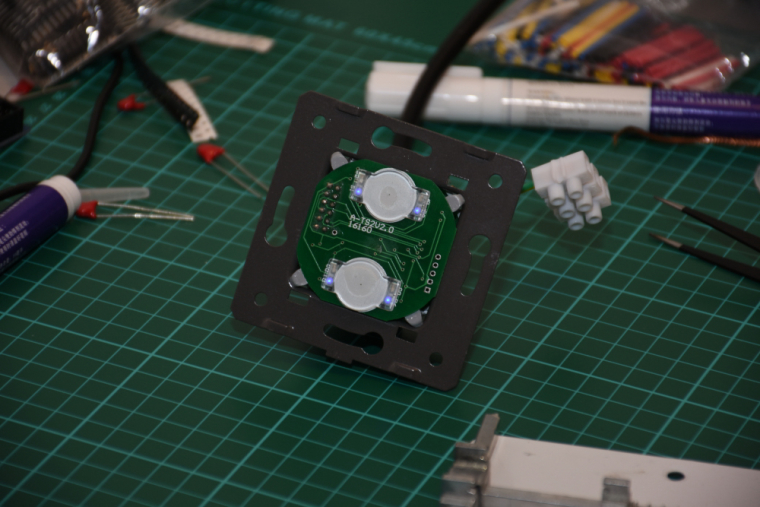
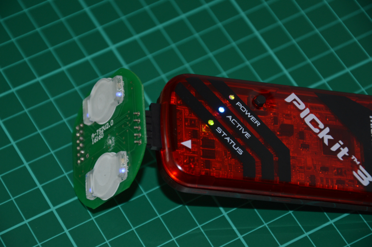
      the touch panel's firmware will be enhanced as well as the controller's firmware, at the moment the touch sensing is reliable and a PoC code run on both of them for testing/debugging purposes. for the controller board I'm collecting additional information for the development on the following link:
      https://forum.mysensors.org/topic/8831/which-sensor-and-msg-type-for-switch-dimmer-node-sender-only

      posted in General Discussion
      andrew
      andrew
    • RE: What did you build today (Pictures) ?

      0_1512830079874_small_20171119_155404.jpg 0_1512830092134_small_20171119_163354.jpg 0_1512830107562_small_20171119_163849.jpg 0_1512830119867_small_20171119_164745.jpg 0_1512830130032_small_20171119_165717.jpg 0_1512830150237_small_20171203_092353.jpg 0_1512830159490_small_20171203_163658.jpg 0_1512830169403_small_20171207_194213.jpg

      posted in General Discussion
      andrew
      andrew
    • RE: CNC PCB milling

      @neverdie indeed, unfortunately it is not straight forward every time. it also took me a while to discover the possibilities and fine tune the results.
      although I'm not an expert, I'll try to create a howto on the topic. it is on my todo list, together with some write-up on my other electronics and hacking projects. πŸ™‚

      posted in General Discussion
      andrew
      andrew
    • RE: CNC PCB milling

      JFYI: CNC 2418 assembly by me πŸ™‚

      CNC 2418 assembly timelapse – 05:41
      β€” AndrΓ‘s Kabai

      I'll try to make a blog to describe the whole pcb cnc milling, tools etc, as well as other diy projects. I'll let you know if there is any notable progress...

      posted in General Discussion
      andrew
      andrew
    • RE: What did you build today (Pictures) ?

      one step further...

      0_1513806197320_small_20171220_092956.jpg

      0_1513806220688_small_20171220_173913.jpg

      0_1513806243839_small_20171220_190510.jpg

      0_1513806273694_small_20171220_204925.jpg

      0_1513806294368_small_20171220_221734.jpg

      0_1513806318135_small_20171220_223817.jpg

      ISP works, FTDI works, test code works, and looks like a genuine board πŸ™‚
      now comes the hard part πŸ˜„

      posted in General Discussion
      andrew
      andrew
    • RE: What did you build today (Pictures) ?

      2 gang EU type livolo customisation, from theory to product... still in progress.

      2_1512829925723_small_20171112_011444.jpg 1_1512829925723_small_20171101_175752.jpg 0_1512829925722_small_20170114_124152.jpg 2_1512829936757_small_20171119_155004.jpg 1_1512829936757_small_20171118_202738.jpg 0_1512829936757_small_20171112_011725.jpg !

      posted in General Discussion
      andrew
      andrew
    • RE: CNC PCB milling

      @neverdie just search for "cnc 2418" on ebay and you can find a lot. almost all of these are Chinese stuff, but works without any issue. based on your needs you can find bigger or smaller versions, such as cnc 1610 or cnc 3020.

      the chosen one should be USB connected and GRBL firmware controlled (check it in the description), so you can use it with open source tools, such as bCNC (https://github.com/vlachoudis/bCNC), chilipeppr (chilipeppr.com/grbl). for isolation milling you should use flatcam (http://flatcam.org/) for the G code preparation based on the gerber and drill files exported from KiCAD/eagle/etc.

      drill sets, milling bit sets and engraving bit sets could be ordered from China for couple of bucks only.
      e.g.:

      • drill bits: https://www.aliexpress.com/item/Free-Shipping-10-Pcs-0-3mm-1-2mm-Import-Carbide-PCB-Drill-Bits-Print-Circuit-Board/32717739217.html
      • carving bits https://www.aliexpress.com/item/New-10pcs-New-Mini-PCB-wood-drill-Bits-Tungsten-Steel-Carbide-PCB-CNC-drill-Bit-Milling/32702792947.html
      • milling bits https://www.aliexpress.com/item/10Pcs-Set-1-8-0-8-3-175mm-Drill-Bits-Engraving-Cutter-Rotary-PCB-CNC-End/32774556522.html
      posted in General Discussion
      andrew
      andrew
    • RE: CNC PCB milling

      @sundberg84 I often use 0.4mm drill bits for vias without any issue. 0.3mm should work as well. The drill set I linked before contains the most frequently used drill bits for PCB drilling (0.3 – 1.2mm).
      regarding to the traces, I have stable and reliable results with 6 mil (0.1524mm) traces / 6 mil clearance, which is also a limitation factor of several PCB manufacturer’s hobby/proto package.

      posted in General Discussion
      andrew
      andrew
    • RE: What did you build today (Pictures) ?

      Hacked Livolo touch switch demo with MySensors network – 00:46
      β€” AndrΓ‘s Kabai

      posted in General Discussion
      andrew
      andrew
    • RE: CNC PCB milling

      hello everyone,

      what is the current status with the quality, fine traces and result stability?
      after a long absence I finally had some time to finish my new board and prototype it.
      I don't have those issues that appearing for some of you, the result is pretty nice, the milling quality is the same across the whole board.
      in this design the thinnest traces were 15mils, and the smallest vias were 0.8mm with 0.3mm drilled holes.

      0_1527023946011_small_20180521_092313.jpg

      1_1527023946013_small_20180521_101938.jpg

      2_1527023946014_small_20180521_102134.jpg

      3_1527023946014_small_20180521_124252.jpg

      just for reference, please see my relevant configuration options detailed below:

      tools

      • cnc: cnc2418
      • carving: 2001 bit (20 degree, 0.1mm end)
      • mounting holes and outline milling: 0.8mm endmill

      config

      • isolation routing: tool dia: 0.1176326981mm; width (# passes): 2; pass overlap: 0.05mm; cut-z: -0.05mm; feed rate: 200
      • milling: tool dia: 0.8mm; cut-z: -1.75mm; feed rate: 170; depth / pass: 0.3mm
      • drilling: feed rate: 120

      software:

      • flatcam
      • bcnc (also for the autoleveling)
      posted in General Discussion
      andrew
      andrew
    • RE: CNC PCB milling

      @neverdie I'll be here πŸ™‚
      you'll love the stuff, I bet for it.

      in the meantime I'll try to finish a howto on the cnc assembly/setup and on other tricks, such as firmware upgrade (which is not officially documented).

      I received the pack like the pics below, it took me two nights to assemble it.

      I would recommend not to use the provided SW pack. or maybe just in a dedicated VM, without internet connection... who knows...

      0_1512862442026_small_20170912_204114.jpg
      0_1512862447860_small_20170912_204451.jpg
      0_1512862451984_small_20170912_204505.jpg
      0_1512862460337_small_20170912_204719.jpg

      posted in General Discussion
      andrew
      andrew
    • RE: CNC PCB milling

      @neverdie so, I expect your first boards tomorrow πŸ™‚

      posted in General Discussion
      andrew
      andrew
    • RE: What did you build today (Pictures) ?

      @neverdie said in What did you build today (Pictures) ?:

      What is that spring loaded contraption? Is it for holding your PCB while you solder it? If so, I can see how that would be handy.

      yes. I have a "third hand" station as well, which is good for through hole parts and pcb handling, but for smd, this could be a life saver.

      this is the exact item which I ordered and which you can see on the photo:
      https://www.aliexpress.com/item/8-12cm-Fixture-Motherboard-PCB-Holder-For-Mobile-Phone-Board-Repair-Tool/32767458535.html

      posted in General Discussion
      andrew
      andrew
    • RE: CNC PCB milling

      I had a chance (and a need) to make a quick PCB prototype again, so I've finished my first real-life exercise with my new CNC3020(T).

      I made two mistakes:

      • as I was in hurry, I did not use enough measurement points for the levelling. A small extra copper remained at two places, hopefully it won't need too much work to get rid of it. The time saved on the levelling will be spent twice on the post-processing... lesson learned... again...
      • I made an unintended short during the levelling and had to reset the controller. Working coordinates were re-defined manually, causing a small shift between the two sides. Once I'll have my new controller ready, this should not happen again.

      Beside these issues, the result still looks amazing.
      Here are some pictures for reference:

      20201106_200847.jpg

      20201106_202113.jpg

      20201106_210426.jpg

      20201106_210444.jpg

      20201106_224057.jpg

      isolation:
      CNC3020T PCB isolation routing – 00:17
      β€” AndrΓ‘s Kabai

      drilling:
      CNC3020T PCB drilling – 00:42
      β€” AndrΓ‘s Kabai

      Conclusion: CNC2030T is an affordable CNC machine which can be easily used for precise PCB prototyping.
      Btw, this was my conclusion for my previous CNC2418 as well. Both of them proved their capabilities. CNC3020T is just better, more robust and good for more stuff.

      To be honest, if one buys a CNC from the super cheap 2418 category and the main goals is PCB milling/drilling, then I do not see any reason to spend money and time on upgrades, as the base machine is good for the job.

      posted in General Discussion
      andrew
      andrew
    • RE: CNC PCB milling

      @sundberg84 well, I've my own PCB UV exposure toolset at home as well, so I can create PCBs both with CNC isolation routing or with photo transfer and etching. depending on the need I can choose the right toolset.

      CNC has some advantages, e.g. no chemicals are necessary; you can easily create (mill) any PCB outline, drilling or hole milling is quick and precise. I managed to create nice 6mil tracks with 6mil isolation without any issue.
      on the other hand the UV exposure version works very well, but due to my printing limitations I managed to go down until 8-10mil traces only. it is also harder to cut and drill the PCBs, or you have to manage to make the proper alignment and set correct reference points for the CNC. but, if you have to remove a lot of copper, then it could be much more efficient compared to CNC isolation routing.

      this small CNCs are pretty cheap. this version has 24x18cm effective work space, which is more than enough for most of the projects. it is also possible to replace the spindle with laser module, so you can use it for laser engraving. I bought this for cca 165 EUR...

      raw PCBs are basically cheap, and I also prefer to have the first results for cheap and without waiting weeks for PCB delivery. so, I create my prototypes at home, test them, and as soon as the given project is ready to "release" (and if it necessary), then I order the design from a professional PCB fab.

      as you see from the pictures above, I had to create couple of designs to properly adjust the mount holes and the PCB outline, I also enhanced the circuit itself, so it was definitely much more cheaper and faster to do all of this at home instead of ordering a set of PCBs for each revision.

      so, long story short, I think it is a good investment πŸ™‚

      posted in General Discussion
      andrew
      andrew
    • RE: CNC PCB milling

      just to have some related pictures in this tread as well, here are some on isolation routing, pcb outline milling and on some test results.

      0_1512852639164_small_20170918_085220.jpg

      0_1512852283772_small_20171101_210626.jpg

      0_1512852428724_small_20171118_194840.jpg

      0_1512852291326_small_20171118_202738.jpg

      posted in General Discussion
      andrew
      andrew
    • RE: CNC PCB milling

      @neverdie I would say, as for a starter kit you should have:

      • drill bit set from 0.3mm to 1.2mm, e.g. this, which I already mentioned before. for vias, through hole components you will use a couple from them. I recommend to have at least 2 pack from this. if you make any mistake (e.g. while moving the cnc head to the relative home without properly realigning the z axis after a tool change /yes, it happened with me :)/) then you can easily break a bit. so have a spare set, just in case...
      • 0.8mm end mills for slot milling, edge cuts and to mill holes which are bigger than your drill bits (e.g. mounting holes). the previously mentioned set is good, as you have multiple options for different tasks, but I still recommend to have some spare one from the 0.8mm end mill in advance.
      • same applies to the carving bit sets. buy one set with multiple size variants (in the given link it is "model 6"), and buy another which just contains 2001 bits (model 2) as these bits will be used the most.
      • PCBs. I usually buy mine from local stores, but your linked one seems to be fine. nothing special, single side or double sided FR4 PCBs, based on your needs (size, thickness). I use 1.6mm thick 1oz FR4 boards, others should work as well.

      you will/might need double sided adhesive tape, and a sacrificial layer for the cnc, to protect your cnc's bed. I applied a wood board cut for proper bed size for this purpose (see before / after pics below). when you drill holes or mill edges/slots then the drilling/milling tools should go through on your PCB, so there should be a sacrificial layer between your cnc's aluminium bed and the PCB. this layer should be replaced when it become very used.

      basically that is it, no rocket science πŸ™‚

      0_1512898935341_small_20170917_185349.jpg
      0_1512898943501_small_20170917_190225.jpg

      posted in General Discussion
      andrew
      andrew
    • RE: CNC PCB milling

      @executivul thank you for the tips and for the shared experience.
      I agree, that the mentioned CNCs, have more robust structure, more powerful spindle, but I guess that the mentioned extra upgrade on the spindle is a bit overkill, especially just to create ad hoc proto PCBs at home.
      just be clear, I know that higher rpm and more powerful spindle could produce better and faster result, ballscrews provide smother and more precise movement, I don't questioning that, but for the price/value/reason of the usage combo I think the cheap smaller versions also do their job quite acceptably.
      2418 is not the fastest, not the strongest, but precise enough for this purpose and it is pretty cheap.

      btw, once I'll have a dedicated working area for my hw hacking stuffs, I'll definitely buy a 6040 or 9060, it is long time ago on my wish list πŸ™‚

      posted in General Discussion
      andrew
      andrew
    • RE: CNC PCB milling

      @ben999 for pcb milling the z touch probe is not so useful. you should do autoleveling instead, on the whole target pcb surface.
      for this the pcb surface and the tool itself should be connected to the cnc controller board dedicated pins (usually the tool is connected with a crocodile clips) during the mapping.
      just quickly googled a video for that:
      CNC 2418 bCNC pcb-gcode – 00:41
      β€” TheVinylrider

      posted in General Discussion
      andrew
      andrew
    • RE: CNC PCB milling

      @NeverDie
      firmware settings: it is stored in the EEPROM, but nothing guarantees that the same location will be used for the same parameters in case of different versions, so the output of "$$" command should be saved, this contains everything which you can manually set up if necessary.

      ER11: take extra care during the installation process to not "harm" the motor's axis. usually the ER11 is pretty tight and howtos mention that the motor should be cooled (by the freezer) and the ER11 should be warmed up before putting them together, to help the mounting process and to prevent unwanted distortion.

      I put the CNC 2418 assembly guide to my share, for ones it is interesting.

      posted in General Discussion
      andrew
      andrew
    • RE: CNC PCB milling

      @neverdie said in CNC PCB milling:

      @andrew said in CNC PCB milling:

      with chilipeppr (in case of grbl 0.9j go for http://chilipeppr.com/grbl , for 1.1.f go for http://chilipeppr.com/jpadie) you can quickly run its default logo engraving path for testing / demo purposes.

      Thanks! That provided exactly what I was looking for. I ran the demo with no etching bit installed, and at first both X and Y seemed to be working, but the adapter coupling eventually loosened on both of them to the point where there was no longer X and Y movement. I've re-tightened tem, and it's working again. I hope it lasts.

      Not sure where I should go next from here though.

      so, as this machine does not have limit switches installed, it is your responsibility to move the gantry to a position, from where you would like to start the job and which provides enough space for each direction movement. usually you have to set a relative zero at the given starting point.

      what is next? did you adjusted the stepper drivers? if not, then do it (I shared the link above). this is necessary to be sure, that the steppers will be powered with enough current (so they will be powerful enough for the given speed related movement and to provide enough force) or will not be overdriven.

      then, I would say try to engrave the chilipeppr logo to a soft material first, have some experience with the cnc.
      then, as I mentioned, discover the flatcam tool and try to create an isolation routing job for a test pcb.
      I already mentioned my confirmed settings for the given jobs (edge / hole milling, isolation routing).
      you should sacrifice some boards for your experience πŸ™‚

      also, try to find your ideal g code sender tool by trying multiple ones.

      posted in General Discussion
      andrew
      andrew
    • RE: CNC PCB milling

      @neverdie you should use one depth, regardless of the trace width. for me 0.05mm worked, see my shared settings above. you should decide the isolation width, this is the main property for the given config, but you should stick for one milling depth only. if the requires isolation width is bigger than the tool width at a given depth, then it will use multiple rounds to reach the given width, but still, with one milling depth.

      posted in General Discussion
      andrew
      andrew
    • RE: CNC PCB milling

      @andrew oh, for those who are interested, flatcam settings were the followings:

      • tool dia: 0.1176326981
      • passes: 2
      • overlap: 0.15
      • cut z: -0.05
      • feed rate: 500
      • spindle: 300 (0-1000 range, but in fact as the pwm signal is inverted now, it is equivalent with 700)

      the engraving tip was 2001 (20degree, 0.1mm end)

      posted in General Discussion
      andrew
      andrew
    • RE: CNC PCB milling

      quick update, just managed to make some test milling.
      pro tip: always check your tip before milling πŸ™‚ I had to trash the one I used for the first two, as its end was chipped

      traces are 6 mil, the footprint is tqfp100 p0.5, built in from kicad.
      some of the the standalone traces are 6 mil with 6 mil clearance, their open end came up, but otherwise it looks ok.

      other 6 mil traces that are connected to pads are actually ok.

      6mil traces where the clearance is 4 mil only were not millet at all, due to the isolation routing path made by flatcam.

      overall, I'm happy with it.

      I've also ordered a dial indicator measurement tool, I'll report the backlash and other measured precision details when it arrives.

      some pics:
      the control box is open and it has an additional external grbl controller now, I'm working on a proper electronics.
      small_20201010_091550.jpg

      small_20201010_100008.jpg small_20201010_095958.jpg

      small_20201010_100018.jpg

      small_20201010_100409.jpg

      posted in General Discussion
      andrew
      andrew
    • Routing table saving vs EEPROM write cycle limitations

      Hi All,

      I'm new to this forum and I love the solutions demonstrated here both on HW and SW level.
      I just started to read/understand the MySensors API and I might have an interesteing finding on the topic.

      As I see, the routing table is periodically saved to the EEPROM based on the following code snippets:

      MyConfig.h

      /**
      * @def MY_ROUTING_TABLE_SAVE_INTERVAL_MS
      * @brief Interval to dump content of routing table to eeprom
      */
      #ifndef MY_ROUTING_TABLE_SAVE_INTERVAL_MS
      #define MY_ROUTING_TABLE_SAVE_INTERVAL_MS    (10*60*1000ul)
      #endif
      

      MyTransport.cpp

      ...
              #if defined(MY_RAM_ROUTING_TABLE_ENABLED)
                      if (hwMillis() - _lastRoutingTableSave > MY_ROUTING_TABLE_SAVE_INTERVAL_MS) {
                              _lastRoutingTableSave = hwMillis();
                              transportSaveRoutingTable();
                      }
              #endif
      ...
      void transportSaveRoutingTable(void) {
              #if defined(MY_RAM_ROUTING_TABLE_ENABLED)
                      hwWriteConfigBlock((void*)&_transportRoutingTable.route, (void*)EEPROM_ROUTES_ADDRESS, SIZE_ROUTES);
                      TRANSPORT_DEBUG(PSTR("TSF:SRT:OK\n"));  //  save routing table
              #endif
      }
      

      So, is this means that the enforced routing table backup to the EEPROM (even if it is not updated) will kill the EEPROM around 1.9 years (10 min saving period means 144 savings per day, thus the 100k EEPROM write life cycle will be reached in 694 days)?

      If I'm right then is it worth to update the API and increase the default saving time in the MyConfig.h (to save a lot of users whom do not know these function in depth and just use the default code) or add some additional code which allows the EEPROM update only when the routing table is updated?

      Or I just miss something and it is handler properly.

      Regards,
      Andrew

      posted in Development
      andrew
      andrew
    • RE: CNC PCB milling

      @mfalkvidd yes, there are some details in my previous post, but it needs a little bit more πŸ™‚
      proper and precise building and calibration of the cnc is essential. the right values should be discovered for various parameters, then with a sw like flatcam you should create an isolation routing path G code, which will be sent to the CNC with a G code sender tool (e.g. bCNC).

      as PCBs are not flat, for fine traces the autoleveling process and the related G code adjustment is pretty important. the tools are supporting this, you just have to use it.

      posted in General Discussion
      andrew
      andrew
    • RE: What did you build today (Pictures) ?

      @rozpruwacz I try to avoid filled copper areas, which could act as RF blockers. as I mentioned, everything is still in progress, in-wall tests will just come. hopefully I'll have time for that in the next 2 weeks.

      posted in General Discussion
      andrew
      andrew
    • RE: CNC PCB milling

      @neverdie it depends on your laser focus and spot size.
      to my "taste" that black spray solution is pretty rudimentary. you can use a small power laser (or stronger lasers with pwm control, which is basically a feature for a lot of cnc controller board as well) with photoresist pcb instead.
      you can buy single or double pcbs with photoresist layer pre-applied, but you can do it at home as well with spray or with dry film.

      posted in General Discussion
      andrew
      andrew
    • RE: CNC PCB milling

      @neverdie just to make the necessary uv exposure to the photoresist layer, then you still have to develop and etch it (see: https://www.youtube.com/watch?v=4SNkzoOvoD8 ).
      with strong lasers you can eliminate the copper as well (see https://www.youtube.com/watch?v=dZYVda4fC4k), but those are not in the hobby category.

      posted in General Discussion
      andrew
      andrew
    • RE: CNC PCB milling

      @neverdie this is exactly the same as mine, even better, it has er11 bit mount on the spindle, which I just ordered for mine. I ordered mine from EU (it is still Chinese) to avoid the issues with the custom, but from China it is cheaper.

      posted in General Discussion
      andrew
      andrew
    • RE: CNC PCB milling

      @neverdie yes, I use standard FR4. if I remember correctly, I read some articles which sad that other PCB types could be more flatter (but the inaccurate flatness could be handled with the autoleveling) and those might not "eat" the carving bits that much. unfortunately I don't have experience with other types but FR4 PCBs.

      posted in General Discussion
      andrew
      andrew
    • RE: What did you build today (Pictures) ?

      @mtiutiu well, that's the dirty hacking part πŸ™‚ electricians will probably not like it.

      so, for first, I've a different approach to control my lamps compared to other in-wall switches and dimmers, due to the fact, that I won't switch the mains directly, with the switch. I have LED ceiling lamps which operate at 12V, but the power supplies (230V to 12V) are in the lamps' body. it could be possible to switch their mains on/off thus to turn the lamps on/off (this is what I do now with standard switches), but it is not possible to dim the lights this way.
      to be able to dim the LEDs as well I'll have a lamp controller node right after the switching PSUs in each lamp. this will be controlled with the in-wall switches (and could be controlled with other nodes/gateways as well), over the air only.

      as all of my wall lamp switch have dual wiring (one line in, two switched line out) I planned the following setup:
      one switched line will be "re-assigned" and wired to N at the lamp. this way, at the wall switch I'll have both L and N. the other switched in-wall line will still forward the L to the lamp, but it will do it directly, to continuously operate the lamp's PSU, which also powers the lamp's controller module.
      the controller will be always on and it will control both the dimming (PWM on the 12V) and the switching wich basically allowing or disabling the 12V from the PSU to the LEDs.

      the in-wall switch will be basically just a radio remote controller this way, but operating from the mains, without any need of batteries.

      I hope that my explanation wasn't too complicated πŸ™‚

      posted in General Discussion
      andrew
      andrew
    • RE: CNC PCB milling

      @neverdie cool, you will have a nice Christmas then πŸ™‚

      I guess you have experience with EDA tools, such as KiCAD or Eagle. this should be the first point. you should export your PCB related gerber and excellon files (top and bottom copper layers, edge cuts) from the given EDA software, then flatcam is the next one.

      in flatcam you have to import the exported files and do all of the necessary preparation work, to create the necessary G codes for every tasks, including isolation routing, milling and drilling.
      this will be your main tool, so discover it as much as possible, including the double sided pcb handling part. most of the manual preparation happens here. maybe this tool is the most important in the whole process.

      after this, you just have to use a G code sender tool which will control the CNC based on the G code, but this is the easy part. you need a CNC for that, so let's get back to this once you have a working setup. maybe in the meantime you can check e.g. bCNC's and chilipeppr's general howtos.

      without a working cnc you can also visualise and simulate the G code, e.g. with CAMotics.

      posted in General Discussion
      andrew
      andrew
    • RE: CNC PCB milling

      in Hungary the VAT is pretty high (27%) which we have to pay on top of the customs fee. moreover, our customs and post response and processing time is very bad. the process could be speeded up if the shipping happens with e.g. dhl and they are allowed to do the customs, but then it also costs extra.
      in the past year customs started to focus very much on packages coming from China, even cheaper and smaller products are captured by them and you are forced to pay them before you can get your stuff 😞

      so for me it was better to buy the cnc from EU, even if it was more expensive compared to the direct Chinese sellers, because at the end of the day, the overall cost was about the same (assuming that I would had to pay the customs and the VAT) but I received the package much more faster.

      posted in General Discussion
      andrew
      andrew
    • RE: CNC PCB milling

      @neverdie most of these entry level CNCs do not have limit switches. the controller board and the grbl firmware is able to to handle them, so you can install them anytime.
      when you power up the CNC, then it will have a "zero" point at the given x/y/z position. then, you can move every axis to the right position and set relative zero (usually at the bottom corner of your PCB) through the controller GUI. every movement declared in the G code will be calculated and will happen from this point. at the end of the given job (e.g. one round of drilling, or one round of isolation routing) the spindle will move back to the relative zero point, and will give back the control to you.
      here I elevate the spindle on the z axis and change the tool, then I zeroing out the z axis again with the new tool, load the next G code job and run it again.

      if you have limit switches then you can declare a tool change position which will be used every time and the cnc can do homing to real physical zero point as well.

      it is nice to have features, but you can do and handle everything without these.

      posted in General Discussion
      andrew
      andrew
    • RE: CNC PCB milling

      to drive/control these CNCs a simple Pi is powerful enough, but it is not necessary to use a separated computer for that.

      chilipeppr runs in a browser (just open chilipeppr.com/grbl). it needs a "remote" serial service to connect over the network (on your local lan/wifi) as from the browser it cannot directly interface with usb. this remote serial service is just an additional software, which should run on a host what is connected to the CNC. this could be the same where you run the browser or really a "remote" host (e.g. a pi). chilipeppr also could stream webcam picture, so if you have one installed to the cnc then you can get realtime remote video as well.
      it is nice, "modern", but online.

      although bcnc isn't that nice as @executivul also mentioned, but I like it. it should run on that host which is connected to the CNC. I didn't have any issues with it so far, single touch z probing and autoleveling worked fine for me. this is what I use now.

      both of them are cross platform tools.

      as I work on os x and linux I did not tested windows tools. there are several more other options both for *nix like systems and for windows as well, but I don't have experience with them, so I cannot recommend anything else.

      I don't use separated computer for the controlling sw, I use my laptop for this job. you can't leave the cnc alone for a long time, the whole process needs multiple manual activities, so from this perspective the "remote" controlling solution maybe not the best idea.

      posted in General Discussion
      andrew
      andrew
    • RE: CNC PCB milling

      @NeverDie about 6 hours, in two nights

      posted in General Discussion
      andrew
      andrew
    • RE: CNC PCB milling

      @neverdie once the assembly is done, you should adjust the stepper drivers' current limiting as well.
      it is pololu a4988, you can find the corresponding details here:
      https://www.pololu.com/product/1182

      then, it is always good idea to have the basic settings exported from the board, just in case... you can do it by "$$" command sent from the g code sender gui or directly from the serial terminal.

      currently I use the following settings, the machine might be able to create nice results with higher feed rates, but I did not have enough time to test it and I sticked to the current working config.

      isolation routing with 2001 bits:

      • z cut: -0.05mm
      • feed rate: 200

      you can calculate the V carving bit's tool width for the given milling depth with the following formula:
      tan(bit angle/2) * milling depth * 2 + bit's end width
      for excel formula the bit angle should be provided in radians, so it should look like this
      tan(radians(bit angle/2)) * milling depth * 2 + bit's end width

      edge cut or hole milling with the 0.8mm endmill:

      • feed rate: 170
      • z cut: -1.7mm
      • multi depth, depth/pass: 0.2mm

      drilling:

      • feed rate: 130
      • z cut: -1.8

      the spindle should be 1000 everywhere.

      most probably your board will not have a bootloader, so it will not be possible to update the firmware via usb serial connection (with avrdude), but it is worth to try it. for me it did not work, so I traced back the MCU pins to the pin rows and used ISP to upgrade the firmware to grbl v1.1f (the board will come with 0.9j if I remember correctly). do not forget to export the gerber settings before you upgrade the firmware, as it will loose those, and you have to re-assign the given values again, after the update.

      the ISP pinout (from the pin row's top left corner):
      Reset -> pin 2
      SCK -> pin 3
      MISO -> pin 12
      MOSI -> pin 13

      5v -> pin1
      gnd-> bottom row(!) e.g. pin 1

      0_1513452548391_small_20171021_232839.jpg

      posted in General Discussion
      andrew
      andrew
    • RE: CNC PCB milling

      @rmtucker it is not 1000rpm, but the pwm control for the whole spindle speed range. see the details in the official document.
      once you use the spindle speed with the value of $30 or above, then the controller will drive the spindle with continuous voltage, without pwm, so it will use its maximum rpm.
      compared to bigger cncs with bigger spindles (e.g. what you can see from @executivul's video above) , 2418's is not that fast (in rpm), on the other hand it should not be "very slow". can you show a video on that?

      posted in General Discussion
      andrew
      andrew
    • RE: CNC PCB milling

      @neverdie yes, it is for "isolating" the pcb from the frame.

      posted in General Discussion
      andrew
      andrew
    • RE: CNC PCB milling

      @neverdie the er-11 should be permanent. this spindle is not powerful enough to handle bigger tools and to mill harder materials.

      you can start with grbl 0.9j, but it is worth to upgrade to 1.1f.
      to the fw upgrade you can use a simple arduino as ISP programmer as well if you do not find your dragon.

      with chilipeppr (in case of grbl 0.9j go for http://chilipeppr.com/grbl , for 1.1.f go for http://chilipeppr.com/jpadie) you can quickly run its default logo engraving path for testing / demo purposes.

      posted in General Discussion
      andrew
      andrew
    • RE: CNC PCB milling

      @neverdie for the cable issue I ordered this cable organizer spiral, although not yet installed it πŸ™‚

      posted in General Discussion
      andrew
      andrew
    • RE: CNC PCB milling

      @neverdie for the touch sensing you should use A5 connector from the headers, connecting it to the actual tool (bit), then a gnd (header's bottom row) connecting to the pcb's surface.

      for the tool connection I use crocodile clamps.

      screws: you did not fasten them enough. at the beginning I also missed some endpoints, but since I put the cnc together, I had no issue with any of my screws.

      posted in General Discussion
      andrew
      andrew
    • RE: What did you build today (Pictures) ?

      @neverdie said in What did you build today (Pictures) ?:

      @boozz What are those 3 pin male connectors called?

      I guess that is molex 3 pin tht pcb connector, like this https://uk.rs-online.com/web/p/pcb-headers/4838477/

      posted in General Discussion
      andrew
      andrew
    • RE: CNC PCB milling

      @andrew for first go for a single touch probing instead of a whole autoleveling session.
      just for testing purposes, start the touch probing from a higher position and touch the gnd wire directly to the spindle's tool to see whether it stops or not. if not, you should stop it manually from the gui, otherwise it could break the tool.
      if everything works well (so you proved that you connections to the pins and the belonging settings are ok), then you can run the simple touch probes or the autoleveling as well.

      posted in General Discussion
      andrew
      andrew
    • RE: CNC PCB milling

      @neverdie one more think I forgot to mention: after I assembled the cnc, I used a little wd40 across each axis and moved each from one end to another. it helped for smooth and "barrier-free" movements.

      posted in General Discussion
      andrew
      andrew
    • RE: CNC PCB milling

      @neverdie said in CNC PCB milling:

      @andrew said in CNC PCB milling:

      you should use A5 connector

      Does using A5 somehow automagically just work, or does it require additional software configuration?

      it should work by default

      posted in General Discussion
      andrew
      andrew
    • RE: CNC PCB milling

      @neverdie yep, I've a linux vm for flatcam and bcnc.

      posted in General Discussion
      andrew
      andrew
    • RE: What did you build today (Pictures) ?

      @yveaux thanks πŸ™‚ I finally managed to document it, there are some other stuff in the queue as well πŸ˜‰

      posted in General Discussion
      andrew
      andrew
    • RE: CNC PCB milling

      @neverdie for er11 fastening you should use two wrenches.

      if you loose steps during the milling, then with the given feed rate / depth / spindle speed combination the cnc / spindle / steppers are not powerful enough.

      if you wood milling depth is not constant then:

      • the wood is not flat
      • the cnc bad is not flat
      • the cnc x axis is not horizontal

      my availability for the next couple of days will be quite limited, so I wish you good luck for experiencing the router and for the first PCBs!

      posted in General Discussion
      andrew
      andrew
    • RE: CNC PCB milling

      @neverdie said in CNC PCB milling:

      I'm stuck. I converted my gerber to gcode using flatcam, and imported it into Chilipeppr:
      0_1514058048699_stuck.png
      On the one hand, it seems to have gotten the dimensioning right, as indicated by the Y1.48in and X1.43in. However, the grid that it's showing is out of sync with that. Each square on the grid is 5mm. It's as though Chilipeppr thinks the entire design fits easily inside a 5mm square, and so when I attempt to do the autoleveling, it comes out completely wrong.

      you can mark the zero point in the pcb designer tool before you export the gergbel, or in flatcam, during the post processing. if you do not define it, then maybe the given zero point could have some "offset" to the effective design. it is not problem, but it could make your life easier if your zero is e.g. at the pcb's corner.
      if you don't want to update the files, then in chilipeppr you can update the probe area to not start from 0,0 but from a given offset.

      posted in General Discussion
      andrew
      andrew
    • RE: CNC PCB milling

      @neverdie said in CNC PCB milling:

      Here's the Model 20 bit again, but this time with flatcam being told that its width is 0.25mm

      how flatcam told you the width or how do you calculate the tool width? it should be specified by you, flatcam does not know how to calculate the tool width in case of carving bits, it varies with the milling depth and depends on the tip's angle and end width. please see the corresponding mathematic formula mentioned in my previous posts.

      you have to generate the isolation routing G code for a specific tool/bit, it cannot be re-used for a different sized one.

      @NeverDie

      • flatcam supports double sided pcb milling with proper alignment holes. using them the isolation routing will be precisely aligned on both sides. you have to drill the alignment holes first, then make the isolation routing on the bottom side, then turn the pcb and finish the isolation routing and the drilling on the top side. it is also highlighted on flatcam's website: http://flatcam.org/manual/procedures.html#side-pcb
      • for isolation routing it is useless to make multiple passes for multiple depth.
      • to make the isolation routing width larger, you should use multiple passes. this is necessary to create a large enough isolation width. to be sure that all copper will be removed between the different passes (e.g. due to cnc inaccuracy or backlash) you should use overlapping. see http://flatcam.org/manual/procedures.html#wide-isolation-routing
      • flatcam supports full copper removal, so it is possible to keep only the traces and pads, although with a carving bit it is very time consuming. you should use endmils for this job. see http://flatcam.org/manual/procedures.html#copper-area-clear
      • it is possible to solder smd parts without solder mask, it is just question of the technique / tool. I've no problem with 0805 sized smd parts and tqfp100 housed ICs, however it is easier to do it if you have solder mask, of course. if you would like to prevent the oxidation only, then you can use tinning. for this purpose I use chemical tinning.
      posted in General Discussion
      andrew
      andrew
    • RE: CNC PCB milling

      @neverdie no. you don't have to remove the drivers. you have to measure everything in place.
      in the mentioned pololu doc/demonstration it is also noted that the given Vref could be measured on the top of the potentiometer (video 3:15)

      posted in General Discussion
      andrew
      andrew
    • RE: CNC PCB milling

      @neverdie said in CNC PCB milling:

      How many microsteps are being used, anyway? I'm not sure where that's defined. Apparently these drivers support up 1/16 steps, but it might be that fewer are actually being used (?). If so, then maybe going to smaller steps would help?

      I notice one of the Pololu boards has the potential for doing 1/32 steps: https://www.pololu.com/product/2133
      and might even be drop-in compatible.

      this cnc controller board is directly pulls the drivers' MS1,2,3 pins to high, which means that it is "hardcoded" to 1/16 microstep. you really don't need smoother steps than this.

      posted in General Discussion
      andrew
      andrew
    • RE: CNC PCB milling

      @neverdie said in CNC PCB milling:

      @andrew said in CNC PCB milling:

      did you manage to create double sided PCB jobs in the meantime based on my suggestion and on flatcam's documentation? it is not a hardcore process, let me know if you stuck at a given step.

      Not sure what kind of pins to use for the alignment.

      I missed this reply from you.
      so, you have to define the alignment holes, typically outside of the actual pcb area, in the "frame".
      you have to define two of them, the rest will be calculated automatically.

      the steps are exactly the same as that you can see on http://flatcam.org/manual/procedures.html#side-pcb

      see the pic below. note, that you don't have to write the coordinates to the input boxes manually, once you click on the design area the corresponding coordinates will be copied to the clipboard, so you can use ctrl-v to fill out the settings.

      • click on the picture to define the axis (X in this example)
      • copy the corresponding coordinates to the point/box input filed
      • click on the design area to define the exact location of the first alignment hole (left side of the actual pcb)
      • copy the corresponding coordinates to the alignment holes input filed
      • click on the design area to define the exact location of the first alignment hole (right side of the actual pcb)
      • copy the corresponding coordinates to the alignment holes input filed. the two set of coordinates have to be separated by coma.
      • configure the alignment holes' drill size
      • click on the create align drill button and you're done. back on the project tab you can find a new drill job which you have to further process to create the belonging G code from it.

      alt text

      posted in General Discussion
      andrew
      andrew
    • RE: What did you build today (Pictures) ?

      @neverdie I hope that you made the prototyping with the cnc πŸ˜‰

      posted in General Discussion
      andrew
      andrew
    • RE: CNC PCB milling

      @neverdie sorry, I'm abroad, with very limited availability, so cannot answer too quickly.

      based on the mentioned facts it seems to me, that the X axis direction pin is sticked to one position, maybe it has a solder bridge to another pin, or vcc / gnd directly.

      alt text

      posted in General Discussion
      andrew
      andrew
    • RE: CNC PCB milling

      @neverdie I told you since the very beginning to make the firmware upgrade! πŸ˜‰

      posted in General Discussion
      andrew
      andrew
    • RE: CNC PCB milling

      @neverdie the order of the process should be the following:

      • drilling the alignment holes (through the PCB into the sacrificial layer)
      • fixing the pcb with the alignment pins/headers
      • isolation routing on the bottom layer
      • flipping the pcb
      • isolation routing on the top layer
      • drilling holes on the top layer
      • milling the pcb outline on the top layer

      as I see your results, you could use alignment holes closer to your actual design's border, but it should be definitely out of the pcb's edge + milling tool width area.

      the very thin traces are most probably caused by:

      • moving and not stable pcb
      • improperly calculated tool width
      • improper autoleveling on the given side
      posted in General Discussion
      andrew
      andrew
    • RE: CNC PCB milling

      @neverdie said in CNC PCB milling:

      How do I mill a slot? Do I treat it the same as a regular hole, except use a routing bit rather than a drill bit when it comes time to cut the slot?

      you can mill holes, which are bigger than your drill bits, you can find a milling section in flat cam when you are working with the drill file.

      you can mill slots as well, for this the slot has to be designed properly in the PCB designer software. you have to draw closed shapes on e.g. the edge cuts layer, then basically you have to follow the same approach in flatcam that is used to create the edge milling cnc job, but instead of the edge lines, you have to select the slots.
      if you design it that way, then you can do both the slot and edge milling at once.

      posted in General Discussion
      andrew
      andrew
    • RE: CNC PCB milling

      @neverdie said in CNC PCB milling:

      I drilled the alignment holes with 0.8mm diameter. I'm using regular male header pins for the alignment, and having tried it, I think 0.8mm is really too tight. Not sure how @andrew is using 0.7mm. Different pins I guess? Anyhow, next time I'll try 0.9mm hole diameter.

      maybe my pins also have different factors, but indeed, the given holes are pretty tight. this helps to prevent unnecessary pcb movements, which is very important if you work with 6mil traces/isolation, as a small unwanted movement could result in wasted pcb. if you work with bigger traces/clearings then it is not as important.

      I would recommend to stick to one size which is good for your selected pins and which does not let the pcb to move.

      posted in General Discussion
      andrew
      andrew
    • RE: CNC PCB milling

      @neverdie for pcb milling a small height difference across the board's area could result in a big negative effect if autoleveling is not performed properly.
      I would double check your autoleveling process, on the other hand, you could also try to use bed flattening with a bigger endmill tool first, then place the pcb to the flattened area. this could help you to eliminate or decrease the cnc assembly or the sacrificial board caused roughness.

      for further details please see the following link:
      http://flatcam.org/manual/procedures.html#bed-flattening

      posted in General Discussion
      andrew
      andrew
    • RE: What did you build today (Pictures) ?

      @jeremushka I reused the top PCB (the touch panel) with its original microcontroller, but with a custom firmware. the bottom PCB was fully replaced with my own designed version. this includes the power supply with additional protections, atmega328, atsha and nrf radio.
      it is running very well on my desk, but I was super busy in the past months so it is not yet installed to the wall.

      in parallel I also had to finish its opposite side, the controller at the lamp. it is also ready for final installation, I just need time for that πŸ™‚

      0_1530125916809_small_20180525_113929.jpg

      0_1530125929873_small_20180525_182927.jpg

      0_1530125937823_small_20180525_183020.jpg

      0_1530125944916_small_20180611_102114.jpg

      posted in General Discussion
      andrew
      andrew
    • RE: CNC PCB milling

      @lamikr pls see one of my very first test I made after I built my cnc. check the TQFP100 footprint.

      for me, the cnc2418 was good choice. with proper assembly it is very stable and its output is stable.
      I was using the cnc for designs down to 10mil traces without any issue.

      so, I have good experience with my low cost cnc but do to the lack of hands-on experience with other devices, I cannot compare or recommend others.

      0_1548754957612_small_20171101_210626.jpg

      1_1548755165291_small_20171119_164624.jpg

      0_1548755165290_small_20171119_163603.jpg

      posted in General Discussion
      andrew
      andrew
    • RE: CNC PCB milling

      Hey @NeverDie, everyone,

      It is good to see how this thread developed over the time and you guys are enjoying the PCB milling.
      Unfortunately I had many other responsibilities and was super busy, so a lot from my projects had to be postponed. Nevertheless I'm still working with my CNC.

      A few days ago I replaced the spindle to a laser module to make same plywood engraving, and the original spindle motor holder (the 3D printed stuff) broke during the unscrew...

      small_20200807_085807.jpg

      I managed to fix the laser module with cable tie. πŸ™‚
      It is ok for the laser, but of course not for the spindle and for the PCB milling.
      Replacement parts are available mostly in packages (e.g. https://www.ebay.com/itm/Replacement-Parts-DIY-Kit-for-CNC-1610-2418-3018-Spindle-Holder-Screw-Polish-Pod/112382449851), but it is possible to print your own version too.
      Some guys already came up with an enhanced design, such as https://www.thingiverse.com/thing:3586273

      I already wanted to make an upgrade on the CNC, so I came to a conclusion, that I will fix the broken part with a custom 3D printed one, then sell the machine.

      I already ordered my new toy, a CNC3020T (EUR 325 + shipping EUR 25):

      cnc3020t.jpg

      Well, I hesitated a lot and almost bought a CNC3040Z-DQ (bigger, better, ball screw), but as currently I really don't have enough space for it (and to be honest, no reason to buy a better/bigger) I sticked with the 3020T. The quality I achieved with my 2418 will be definitely reproducible and this is enough.

      I just read the endmill isolation routing posts. Interesting stuff.
      I'm curious whether you can use smaller ones to deal with the 6mil/6mil trace/isolation sizes.

      Happy milling and cheers!

      posted in General Discussion
      andrew
      andrew
    • RE: CNC PCB milling

      @niallain it is 3020T which uses trapezoidal screws. "Z" uses ball screws.
      you can check the "official" technical details on the item's specification (scroll down to the description then click on the "specification"):

      ...
      Driving units X axis: 1204 trapezoidal screws
      Driving units Y axis: 1204 trapezoidal screws
      Driving units Z axis: 1204 trapezoidal screws
      ...
      Repeat accuracy: 0.05mm
      ...
      Spindle precision: radial beat acuities 0.03 mm
      ...

      Note that none of these parameters above are confirmed. To be honest I don't have the right measurement tools for that, but the fine trace PCB samples will prove it, or not πŸ™‚

      posted in General Discussion
      andrew
      andrew
    • RE: CNC PCB milling

      @NeverDie after changing the tool I always make a single touch probe so Z level can be adjusted to the new tool properly.

      This is necessary even for the PCB milling. After the levelling is done, a single touch probe is needed somewhere in the working are to set the Z0 and to make it as a reference point for the bed levelling mesh.
      At least this is how it is done in bCNC.
      After the isolation routing is done, I make a single Z touch probe for each drill bits to set the correct Z0 for the given bit. This is done in the same way as in case for the PCB probing.
      Note that as the drilling on Z axis does not require high precision (basically if your drilling depth is slightly bigger than the PCB thickness, then even if your Z is just roughly adjusted to the PCB top, it will do the job).

      As I currently work with PCBs only, no other touch probe was necessary, however for woodworking (or for other non conductive materials) one can use a dedicated "touch probe".

      There are nice solutions form a simple PCB:
      DIY Z Probe For CNC Machine – 08:26
      β€” Nikodem Bartnik

      or
      UPGRADE CNC 3018/ PRO Z-PROBE | Z Axis tool probe | GRBL | EASEL | SUB – 10:02
      β€” Cosmo Channel

      or you can buy a cheap touch probe as well:
      https://www.aliexpress.com/item/4001010640247.html

      or you can go for nicer and more expensive professional touch probes πŸ™‚

      posted in General Discussion
      andrew
      andrew
    • RE: CNC PCB milling

      @NeverDie : well,

      • for PCB milling this spring loaded stuff simply does not work, as the whole area should be mapped.
      • for non-PCB Z zeroing it could be good, however in such case (imho) this is just an over complicated/engineered method for a simple probing.

      when you need a single z touch levelling then better to have a rock solid solution rather then have additional moving parts and potential other vectors for a failure. even with a slow feed rate, a single probe can be done in an acceptable time period, so why should you risk your result?
      I can imagine that this spring stuff can help you when you approaching with quite high feed rate for first, but in such case I would be afraid of the "wearing" of the probe surface over time and the inaccuracy it may cause later on.

      btw, the "double probing" with fast then a slower feed rate is used by other sw/firmware, e.g. marlin does the same (in certain configurations) for 3d printers.

      posted in General Discussion
      andrew
      andrew