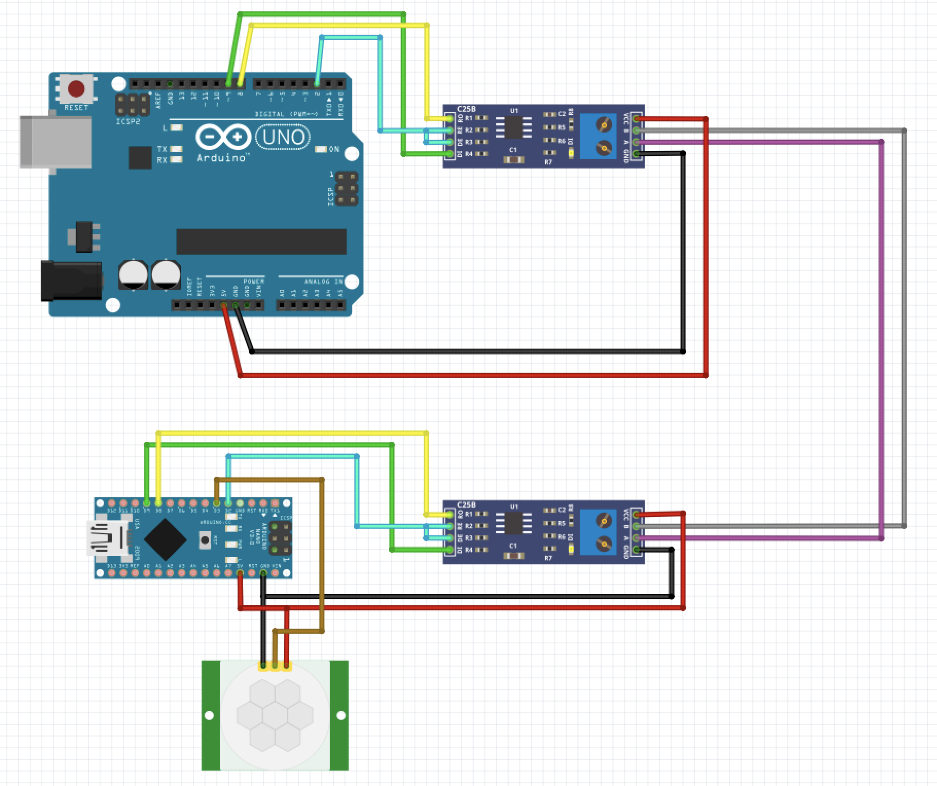
OK I found the reason.
I had to disable MY_RADIO_RF24 and MY_RF24_PA_LEVEL
so I commented out line 44 and 51 and it worked.
Sketch code:
/**
* The MySensors Arduino library handles the wireless radio link and protocol
* between your home built sensors/actuators and HA controller of choice.
* The sensors forms a self healing radio network with optional repeaters. Each
* repeater and gateway builds a routing tables in EEPROM which keeps track of the
* network topology allowing messages to be routed to nodes.
*
* Created by Henrik Ekblad <henrik.ekblad@mysensors.org>
* Copyright (C) 2013-2019 Sensnology AB
* Full contributor list: https://github.com/mysensors/MySensors/graphs/contributors
*
* Documentation: http://www.mysensors.org
* Support Forum: http://forum.mysensors.org
*
* This program is free software; you can redistribute it and/or
* modify it under the terms of the GNU General Public License
* version 2 as published by the Free Software Foundation.
*
*******************************
*
* DESCRIPTION
* The ArduinoGateway prints data received from sensors on the serial link.
* The gateway accepts input on serial which will be sent out on radio network.
*
* The GW code is designed for Arduino Nano 328p / 16MHz
*
* Wire connections (OPTIONAL):
* - Inclusion button should be connected between digital pin 3 and GND
* - RX/TX/ERR leds need to be connected between +5V (anode) and digital pin 6/5/4 with resistor 270-330R in a series
*
* LEDs (OPTIONAL):
* - To use the feature, uncomment any of the MY_DEFAULT_xx_LED_PINs
* - RX (green) - blink fast on radio message received. In inclusion mode will blink fast only on presentation received
* - TX (yellow) - blink fast on radio message transmitted. In inclusion mode will blink slowly
* - ERR (red) - fast blink on error during transmission error or receive crc error
*
*/
// Enable debug prints to serial monitor
#define MY_DEBUG
// Enable and select radio type attached
//#define MY_RADIO_RF24
//#define MY_RADIO_NRF5_ESB
//#define MY_RADIO_RFM69
//#define MY_RADIO_RFM95
// Set LOW transmit power level as default, if you have an amplified NRF-module and
// power your radio separately with a good regulator you can turn up PA level.
//#define MY_RF24_PA_LEVEL RF24_PA_LOW
// Enable serial gateway
#define MY_GATEWAY_SERIAL
// Define a lower baud rate for Arduinos running on 8 MHz (Arduino Pro Mini 3.3V & SenseBender)
//#if F_CPU == 8000000L
#define MY_BAUD_RATE 38400
//#define MY_BAUD_RATE 115200
//#endif
// Enable inclusion mode
#define MY_INCLUSION_MODE_FEATURE
// Enable Inclusion mode button on gateway
//#define MY_INCLUSION_BUTTON_FEATURE
// Inverses behavior of inclusion button (if using external pullup)
//#define MY_INCLUSION_BUTTON_EXTERNAL_PULLUP
// Set inclusion mode duration (in seconds)
#define MY_INCLUSION_MODE_DURATION 60
// Digital pin used for inclusion mode button
//#define MY_INCLUSION_MODE_BUTTON_PIN 3
// Set blinking period
#define MY_DEFAULT_LED_BLINK_PERIOD 300
// Inverses the behavior of leds
//#define MY_WITH_LEDS_BLINKING_INVERSE
// Flash leds on rx/tx/err
// Uncomment to override default HW configurations
//#define MY_DEFAULT_ERR_LED_PIN 4 // Error led pin
//#define MY_DEFAULT_RX_LED_PIN 6 // Receive led pin
//#define MY_DEFAULT_TX_LED_PIN 5 // the PCB, on board LED
#include <MySensors.h>
uint32_t SLEEP_TIME = 120000; // Sleep time between reports (in milliseconds)
#define DIGITAL_INPUT_SENSOR 3 // The digital input you attached your motion sensor. (Only 2 and 3 generates interrupt!)
#define CHILD_ID 1 // Id of the sensor child
// Initialize motion message
MyMessage msg(CHILD_ID, V_TRIPPED);
void setup()
{
// Setup locally attached sensors
pinMode(DIGITAL_INPUT_SENSOR, INPUT); // sets the motion sensor digital pin as input
}
void presentation()
{
// Present locally attached sensors
// Send the sketch version information to the gateway and Controller
sendSketchInfo("Motion Sensor", "1.0");
// Register all sensors to gw (they will be created as child devices)
present(CHILD_ID, S_MOTION);
}
void loop()
{
// Send locally attached sensor data here
// Read digital motion value
bool tripped = digitalRead(DIGITAL_INPUT_SENSOR) == HIGH;
Serial.println(tripped);
send(msg.set(tripped?"1":"0")); // Send tripped value to gw
// Sleep until interrupt comes in on motion sensor. Send update every two minute.
sleep(digitalPinToInterrupt(DIGITAL_INPUT_SENSOR), CHANGE, SLEEP_TIME);
}
I've also changed some lines in my configuration.yml
mysensors:
gateways:
- device: '/dev/ttyUSB0'
persistence_file: 'mysensors/mysensors.json'
baud_rate: 38400
persistence: true
version: '2.3.2'
And the motion sensor showed up as Motion Sensor