Skip to content
  • OpenHardware.io
  • Categories
  • Recent
  • Tags
  • Popular
Skins
  • Light
  • Brite
  • Cerulean
  • Cosmo
  • Flatly
  • Journal
  • Litera
  • Lumen
  • Lux
  • Materia
  • Minty
  • Morph
  • Pulse
  • Sandstone
  • Simplex
  • Sketchy
  • Spacelab
  • United
  • Yeti
  • Zephyr
  • Dark
  • Cyborg
  • Darkly
  • Quartz
  • Slate
  • Solar
  • Superhero
  • Vapor

  • Default (No Skin)
  • No Skin
Collapse
Brand Logo
cimba007C

cimba007

@cimba007
  • Getting Started
  • Controller
  • Build
  • Hardware
  • Download/API
  • Forum
  • Store
About
Posts
127
Topics
10
Shares
0
Groups
0
Followers
1
Following
0

Posts

Recent Best Controversial

  • Cheap dirty way to send a raw-mysensors message?
    cimba007C cimba007

    After many hours trial and error I present you .. the raw-mysensors-client!!

    MyGateway: ESP8266 + mysensorsMQTT
    MyNode: https://github.com/Miceuz/PlantWateringAlarm
    MyNode-MCU: Attiny44 (MemoryFootprint: 87% of 4KB)
    ArduinoCore: https://github.com/SpenceKonde/ATTinyCore
    ArduinoCore-PinLayout: Counterclockwise (like AttinyCore)
    Note: The default "counterclockwise"pinout is the alternate pinout shown here: https://github.com/SpenceKonde/ATTinyCore/blob/master/avr/extras/ATtiny_x4.md

    The important hint is here (http://tmrh20.github.io/RF24/ATTiny.html)

    Connect MOSI of the RF24 to PA5 of the attiny and MISO of the RF24 to PA6 of the attiny.
    CE = 8
    CSN = 7

    To get the connection done right DONT .. i mean DO NOT BECAUSE IT DOESNT FUCKING WORK connect MOSI of the RF24 to MOSI of the attiny. RF24 uses a embedded implementation of the USI-engine found on some AtTiny's.

    radio-initilisation

        radio.begin(); // Start up the radio
        radio.setDataRate(RF24_250KBPS);
        radio.setAutoAck(1); // Ensure autoACK is enabled
        radio.setRetries(15,15); // Max delay between retries & number of retries
        //radio.setPayloadSize(8);
        radio.enableDynamicPayloads();
        radio.setPALevel(RF24_PA_MAX);
        byte tx_address[] = { 0x00, 0xFC, 0xE1, 0xA8, 0xA8 };
        //byte tx_address[] = { 0xA8, 0xA8, 0xE1, 0xFC, 0x00 };
        radio.openWritingPipe(tx_address);
        radio.stopListening();
    

    Send-Function:

    void sendHumidity(uint16_t humidity)
    {
        // snprintf_P(_fmtBuffer, MY_GATEWAY_MAX_SEND_LENGTH, PSTR("%s/%d/%d/%d/%d/%d"), prefix, message.sender, message.sensor, mGetCommand(message), mGetAck(message), message.type);
        // X8X22<\0><\n>!<7>7AY0;255;3;0;9;TSF:MSG:READ,50-50-0,s=55,c=1,t=7,pt=1,l=1,sg=0:65<\n>
        // 0;255;3;0;9;Sending message on topic: domoticz/in/MyMQTT/50/55/1/0/7<\n>
        
        #define LAST_NODE_ID  50  // last
        #define NODE_ID       50  // sender
        #define GATEWAY_ID    0   // destination
        
                                  // version_length     // 5 bit - Length of payload // 1 bit - Signed flag // 2 bit - Protocol version
                                  // command_ack_payload // 3 bit - Payload data type // 1 bit - Is ack messsage - Indicator that this is the actual ack message. // 1 bit - Request an ack - Indicator that receiver should send an ack back. // 3 bit - Command type
        
        #define SENSOR_TYPE   7   // type S_HUM = 7
        #define SENSOR_ID     55  // sensor-id
        byte test[] = { LAST_NODE_ID, NODE_ID, GATEWAY_ID, 0b00010010, 0b01100001,  SENSOR_TYPE, SENSOR_ID, (uint8_t)(humidity & 0x00FF), (uint8_t)((humidity >> 8) & 0x00FF),  0x00 };
        radio.write(test,9);
    }
    

    I am not quite sure yet if the message-types etc. are right but I am trying to find this out. 'A' (dec 65) is the "value" of my humidity .. next step is to make this a real value ofc.

    Proof at domoticz:
    0_1499525234377_upload-22170821-6116-4d1a-a08b-c0631b3fac15

    @gohan: In the file MyConfig.h I commented this out:

    /**
     * @def MY_REGISTRATION_FEATURE
     * @brief If enabled, node has to register to gateway/controller before allowed to send sensor data.
     */
    // #define MY_REGISTRATION_FEATURE
    

    This will skip the whole hasse of registering the client properly (which I can't .. remember 87% of flash is full)

    Development

  • Microwave Radar Module as PIR replacement.
    cimba007C cimba007

    @Yveaux I did some extensive testing on the FC1816 module and I thought I might drop my experience:

    http://electronics.stackexchange.com/questions/226031/pinout-of-microwave-motion-sensor-fc1816

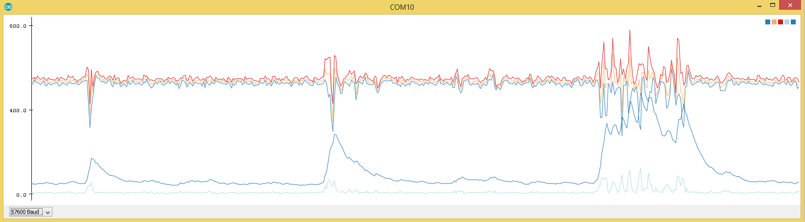
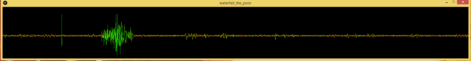
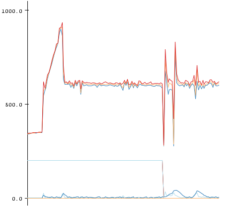
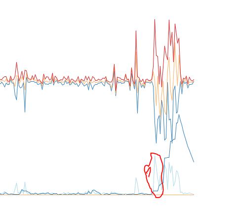
    In the end I used an 150ohm Series resistor + ~100µF cap behind this to power the FC1816. This eliminated much of the leftover noise. If this is not enough I presented a way to lower the module amplification. In the end I deactivated the biss-trigger output alltogether and grabbed the raw signal. Doing some manual processing:

    1. take 100 reads
    2. get the stddev (statistics library)
    3. high stddev = high fluctuation in values = movement

    Take a look at my current working copy of my code for the FC1816:

    Some notes:

    I power the VCC of the FC1816 from some arduino pins. Thus I can deactivate the microwave sensor at will. This is still not recommended. If you visit the previous link you can see that the BISS has some kind of "warmup"-Period.

    I use 3,3Volt to power the NRF24, the arduino and the FC1816 and suffered no strange consequences so far.

    Get get some insight about the link quality of the NRF24 I made the function RF24_getObserverTX() accessible from user-space:

    MySensors\drivers\RF24\RF24.cpp

    uint8_t RF24_getObserveTX(void)
    {
    	return RF24_readByteRegister(OBSERVE_TX);
    }
    

    MySensors\drivers\RF24\RF24.h

    uint8_t RF24_getObserveTX(void);
    

    The Idea behind the OBSERVE_TX register is that the lower byte presents the number of retrys the NRF24 used in the last send.
    The upper 4 bits present the number of total failed packets. I suggest using (0x0F & RF24_getObserveTX()) to get a usable number 0-15 presenting the retry-count. Anything > 0 suggests a packetloss on your link. 15 most likely will mean you ran into an complete fail as the max number of retrys was exhausted.

    This number might be capped by

    // ARD, auto retry count
    #define RF24_ARC 15
    

    from the RF24.h driver-file.

    TO not run into compiling errors you might need:

    http://arduiniana.org/libraries/streaming/
    https://github.com/RobTillaart/Arduino/tree/master/libraries/Statistic

    MicrowaveRadarSensor.ino

    #include <Streaming.h>
    #include "Statistic.h"
    
    
    /**
     * The MySensors Arduino library handles the wireless radio link and protocol
     * between your home built sensors/actuators and HA controller of choice.
     * The sensors forms a self healing radio network with optional repeaters. Each
     * repeater and gateway builds a routing tables in EEPROM which keeps track of the
     * network topology allowing messages to be routed to nodes.
     *
     * Created by Henrik Ekblad <henrik.ekblad@mysensors.org>
     * Copyright (C) 2013-2015 Sensnology AB
     * Full contributor list: https://github.com/mysensors/Arduino/graphs/contributors
     *
     * Documentation: http://www.mysensors.org
     * Support Forum: http://forum.mysensors.org
     *
     * This program is free software; you can redistribute it and/or
     * modify it under the terms of the GNU General Public License
     * version 2 as published by the Free Software Foundation.
     *
     *******************************
     *
     * REVISION HISTORY
     * Version 1.0 - Henrik EKblad
     * 
     * DESCRIPTION
     * Example sketch showing how to measue light level using a LM393 photo-resistor 
     * http://www.mysensors.org/build/light
     */
    
    #define MY_NODE_ID 10
    #define MY_BAUD_RATE 57600
    
    // Enable debug prints to serial monitor
    //#define MY_DEBUG 
    
    // Enable and select radio type attached
    #define MY_RADIO_NRF24
    //#define MY_RADIO_RFM69
    
    #include <SPI.h>
    #include <MySensors.h>  
    
    #define LIGHT_SENSOR_ANALOG_PIN A3
    #define MICRO_SENSOR_ANALOG_PIN A1
    
    unsigned long SLEEP_TIME = 1000; // Sleep time between reads (in milliseconds)
    
    #define CHILD_ID_LIGHT 0
    #define CHILD_ID_MICRO 0
    #define TRIPPED_THRESHOLD 50
    
    MyMessage msg_light(CHILD_ID_LIGHT, V_LIGHT_LEVEL); // 23
    MyMessage msg_micro(CHILD_ID_MICRO, V_TRIPPED);     // 16
    MyMessage msg_micro_debug(0,V_VAR1);   // 24
    MyMessage msg_obstx_debug(0,V_VAR2);   // 25
    
    void before()
    {
      // LightSensor
      pinMode(A3,INPUT_PULLUP);
      pinMode(A2,OUTPUT);
      digitalWrite(A2,LOW);  
    
      // Microwave
      pinMode(5,OUTPUT);        // VCC BISS0001
      digitalWrite(5,HIGH);
      
      pinMode(6,OUTPUT);        // Enabled
      digitalWrite(6,LOW);      // Enable
      
      pinMode(7,OUTPUT);        // GND
      digitalWrite(7,LOW);
      
      pinMode(8,OUTPUT);        // VCC Radar
      digitalWrite(8,HIGH);
    
      pinMode(A1,INPUT);        // PIR 2nd Amplification Stage
    
      // Other
    }
    void setup()
    {
     
    }
    void presentation()  {
      // Send the sketch version information to the gateway and Controller
      sendSketchInfo("Microwave+Light", "1.0");
    
      // Register all sensors to gateway (they will be created as child devices)
      // https://www.mysensors.org/download/serial_api_20#sensor-type
      present(CHILD_ID_LIGHT, S_LIGHT_LEVEL);
      present(CHILD_ID_MICRO, S_MOTION);
      //present(0, S_ARDUINO_NODE);
      
    }
    
    void loop()      
    {     
      // Report VCC
      static long vcc = readVcc();
      static int vccpercent = map(vcc,1800,3280,0,100);
      sendBatteryLevel(max(min(vccpercent,100),0),false);
      Serial << "| vcc: ";
      p(F("%4d"),vcc);
      Serial << " ";
      // Required for ack
      //wait(100);
    
      // Report LightLevel
      analogRead(LIGHT_SENSOR_ANALOG_PIN);
      int lightLevel_raw = analogRead(LIGHT_SENSOR_ANALOG_PIN);
      int lightLevel = (1023-lightLevel_raw)/10.23; // as of 1023 !!
      Serial << "| light_raw: ";
      p(F("%4d"),lightLevel_raw);
      Serial << " ";
      Serial << "| light: ";
      p(F("%3d"),lightLevel);
      Serial << " ";
      send(msg_light.set(lightLevel),false);
    
      // Report WirelessLink Information
      Serial << "| observe_tx: ";
      uint8_t obstx = RF24_getObserveTX();
      p(F("%X"),obstx);
      Serial << " ";
      send(msg_obstx_debug.set(0x0F&obstx),false);
     
      // Report Microwave
      Statistic mw_s;
      mw_s.clear();
      
      delay(90);
      analogRead(MICRO_SENSOR_ANALOG_PIN);
      delay(10);
      for(int i = 0; i < 1000; i++)
      {
        mw_s.add(analogRead(MICRO_SENSOR_ANALOG_PIN));
        delay(1);
      }
      Serial << "| mw_raw: ";
      int stddev = mw_s.pop_stdev();
      p(F("%4d"),stddev);
      Serial << " ";
      
      Serial << "| mw_min: ";
      int minimum = mw_s.minimum();
      p(F("%4d"),minimum);
      Serial << " ";
    
      Serial << "| mw_max: ";
      int maximum = mw_s.maximum();
      p(F("%4d"),maximum);
      Serial << " ";
      
      Serial << "| mw: " << (stddev > TRIPPED_THRESHOLD ? "1" : "0") << " ";
      send(msg_micro_debug.set(stddev),false);
      while(!send(msg_micro.set(stddev > TRIPPED_THRESHOLD ? "1" : "0"),true))
      {
        wait(10);
      }
      
      if(isTransportOK()) 
        wait(100);
      else
        wait(1000);
      Serial << endl;
      //mysleep(500);
    
    }
    // https://forum.mysensors.org/topic/3463/m_ack_variable-or-m_set_variable/2
    void receive(const MyMessage &message) {
      if (message.isAck()) {
          Serial.print("| GW ack");
          }
    }
    

    Helper.ino

    long readVcc() {
      // Read 1.1V reference against AVcc
      // set the reference to Vcc and the measurement to the internal 1.1V reference
      #if defined(__AVR_ATmega32U4__) || defined(__AVR_ATmega1280__) || defined(__AVR_ATmega2560__)
        ADMUX = _BV(REFS0) | _BV(MUX4) | _BV(MUX3) | _BV(MUX2) | _BV(MUX1);
      #elif defined (__AVR_ATtiny24__) || defined(__AVR_ATtiny44__) || defined(__AVR_ATtiny84__)
        ADMUX = _BV(MUX5) | _BV(MUX0);
      #elif defined (__AVR_ATtiny25__) || defined(__AVR_ATtiny45__) || defined(__AVR_ATtiny85__)
        ADMUX = _BV(MUX3) | _BV(MUX2);
      #else
        ADMUX = _BV(REFS0) | _BV(MUX3) | _BV(MUX2) | _BV(MUX1);
      #endif  
    
      delay(2); // Wait for Vref to settle
      ADCSRA |= _BV(ADSC); // Start conversion
      while (bit_is_set(ADCSRA,ADSC)); // measuring
    
      uint8_t low  = ADCL; // must read ADCL first - it then locks ADCH  
      uint8_t high = ADCH; // unlocks both
    
      long result = (high<<8) | low;
    
      result = 1125300L / result; // Calculate Vcc (in mV); 1125300 = 1.1*1023*1000
      //result *= 1.0637;
      return result; // Vcc in millivolts
    }
    
    #include <stdarg.h>
    void p(const __FlashStringHelper *fmt, ... ){
      char buf[128]; // resulting string limited to 128 chars
      va_list args;
      va_start (args, fmt);
    #ifdef __AVR__
      vsnprintf_P(buf, sizeof(buf), (const char *)fmt, args); // progmem for AVR
    #else
      vsnprintf(buf, sizeof(buf), (const char *)fmt, args); // for the rest of the world
    #endif
      va_end(args);
      Serial.print(buf);
    }
    
    void mysleep(int SLEEP_TIME)
    {
        if(isTransportOK()){
          Serial << "| wait ";
          wait(25);
          Serial << "| zZz > ";
    
          sleep(SLEEP_TIME);
          Serial << "| < zZz " << endl;
        } 
        else {
          wait(1000);
        }
    }
    
    Hardware

  • Microwave Radar Module as PIR replacement.
    cimba007C cimba007

    All things from my previous post regarding the wiring are still needed:

    Here is a stripped down example on how to use the FC1816 Microwave Sensor. You need the following library:

    https://github.com/RobTillaart/Arduino/tree/master/libraries/Statistic

    #include "Statistic.h"
    
    #define MICRO_SENSOR_ANALOG_PIN A1
    
    void setup()
    {
      
      Serial.begin(57600);
      Serial.print("begin");
      
      // Microwave
      pinMode(5,OUTPUT);        // VCC BISS0001
      digitalWrite(5,HIGH);
      
      pinMode(6,OUTPUT);        // Enabled
      digitalWrite(6,LOW);      // DISABLE PLEASE!
      
      pinMode(7,OUTPUT);        // GND
      digitalWrite(7,LOW);
    
      pinMode(A1,INPUT);        // PIR 2nd amplification stage
    
      pinMode(A0,OUTPUT);       // UPD microwave generator
      digitalWrite(A0,HIGH);
    
    }
    
    void loop()      
    {     
      // Report Microwave
      static Statistic mw_s;
      static uint16_t stdev_sum = 0;
      //mw_s.clear();
    
      //digitalWrite(8,HIGH);
      //delay(100);
      analogRead(MICRO_SENSOR_ANALOG_PIN);
      uint16_t reading;
      for(int i = 0; i < 200; i++)
      {
        reading = analogRead(MICRO_SENSOR_ANALOG_PIN);
        mw_s.add(reading);
        //Serial.println(reading);
        //Serial.flush();
        //delay(50);
        //LowPower.powerDown(SLEEP_60MS, ADC_ON, BOD_OFF);  
        //delay(1);
      }
      Serial.print(mw_s.minimum());   Serial.print(",");
      Serial.print(mw_s.average());   Serial.print(",");
      Serial.print(mw_s.maximum());   Serial.print(",");
      Serial.print(mw_s.pop_stdev()); Serial.print(",");
      stdev_sum += mw_s.pop_stdev();
      Serial.print(stdev_sum); //Serial.print(",");
      Serial.println();
      stdev_sum *= 0.9;
      mw_s.clear();
    }
    

    I just had the idea to sum up the std-dev and decrease it by 10% every round. Thus the code is less prone to peaks.

    0_1471429474464_upload-9c26c9f3-6ccd-4aaf-9bcc-797ad4c03be4

    stdev_sum is the lower dark blue line which can now be much easier compared to a threshold.

    Some measurement with my µCurrent-Gold:

    Unmodified code as above, power LED removed from ProMini @ 8Mhz internal osci with LDO desoldered
    4,8mA

    I tried to put the FC1816 into sleep by disable the power to the Microwave generator but this doesn't work.
    I modified the fuses for 8Mhz with 0ms wakeup delay for stabelizing the oscillator. No risk no phun ;-)

    The most practical solution I got to replace a PIR (still nothing as close as a PIR ;-ö)

    1530µA

    with this code:

    Note that the radar generator just can't be disable as it needs 10-15seconds to stabelize after power up

    #include <LowPower.h>
    
    #include "Statistic.h"
    
    #define MICRO_SENSOR_ANALOG_PIN A1
    
    void setup()
    {
      
      Serial.begin(57600);
      Serial.print("begin");
      
      // Microwave
      pinMode(5,OUTPUT);        // VCC BISS0001
      digitalWrite(5,HIGH);
      
      pinMode(6,OUTPUT);        // Enabled
      digitalWrite(6,LOW);      // DISABLE PLEASE!
      
      pinMode(7,OUTPUT);        // GND
      digitalWrite(7,LOW);
    
      pinMode(A1,INPUT);        // PIR 2nd amplification stage
    
      pinMode(A0,OUTPUT);       // UPD microwave generator
      digitalWrite(A0,HIGH);
    
    }
    
    void loop()      
    {     
      // Report Microwave
      static Statistic mw_s;
      static uint16_t stdev_sum = 0;
      //mw_s.clear();
    
      
      //delay(100);
      analogRead(MICRO_SENSOR_ANALOG_PIN);
      uint16_t reading;
      for(int i = 0; i < 10; i++)
      {
        LowPower.powerDown(SLEEP_15Ms, ADC_ON, BOD_OFF);  
        reading = analogRead(MICRO_SENSOR_ANALOG_PIN);
        mw_s.add(reading);
        //Serial.println(reading);
        //Serial.flush();
        //delay(50);
        LowPower.powerDown(SLEEP_15Ms, ADC_ON, BOD_OFF);  
        //delay(1);
      }
      Serial.print(mw_s.minimum());   Serial.print(",");
      Serial.print(mw_s.average());   Serial.print(",");
      Serial.print(mw_s.maximum());   Serial.print(",");
      Serial.print(mw_s.pop_stdev()); Serial.print(",");
      stdev_sum += mw_s.pop_stdev();
      Serial.print(stdev_sum); //Serial.print(",");
      Serial.println();
      Serial.flush();
      stdev_sum *= 0.9;
      mw_s.clear();
      
    }
    
    Hardware

  • New Homepage design
    cimba007C cimba007

    I find the huge gap between the title and the #Post very .. annonying. Now I have to move my had from totally left of my screen to totally right to read the latest post for each topic.

    0_1473707200319_upload-e392565b-9a45-4b00-a1c2-c708d567fbb6

    General Discussion

  • Microwave Radar Module as PIR replacement.
    cimba007C cimba007

    Currently I don't plan to make a library .. a library implies that the sensor is very easy to use .. plug in + import library.

    The FC1816 is not such a sensor.

    • Needs Voltage-Supply filter (RC Section)
    • Need separate cable to grab the signal at the 2nd amplification stage
    • Need potentiometer to lower the amplification
    • Is very prone to random noise (in fact even entering RF24 or ATMEGA328 low power mode might increase noise floor a lot)

    Using a "simple to use" library and not getting the expected result of an "easy"-sensor would be very disappointing. For now I would say this is an advanced sensor with some pitfalls.

    I update this thread with my findings to hopefully make everybodys life a bit easyer if you want to tinker with the FC1816 although you now know it is a little beast ;-)

    If you need any help just ask here and I will support you the best I can.

    Hardware

  • low power designe
    cimba007C cimba007

    One addition:

    If you power the Arduino directly (e.g. 2x AA = ~3,00V max) you can use ( http://provideyourown.com/2012/secret-arduino-voltmeter-measure-battery-voltage/ ). This will ofc. not work if you power your setup via VoltageRegulator.

    In addition to mfalkvidd's link have alook at https://www.mysensors.org/download/sensor_api_20#sleeping

    It describes how to use the sleep function to put the Arduino+Radio in sleep mode.

    Feature Requests

  • Watchdog on 2.0
    cimba007C cimba007

    Have you tried to enable #define MY_DEBUG and have a Serial terminal opened all the time?

    Maybe you can get some clues on where the sketch "hangs up"

    General Discussion 2.0 mqtt watchdog

  • Microwave Radar Module as PIR replacement.
    cimba007C cimba007

    @Yveaux From my oppinion the radar modules are not suited for battery usage. Their drain something like 3-5mA and are not easy to put to sleep. Remember the warm-up period of the BISS. It seems to be like 10-15seconds.

    The plots are from another sketch, not the one I posted but using them is pretty straight forward.

    In my sketch have a look at these parts:

      Serial << "| mw_min: ";
      int minimum = mw_s.minimum();
      p(F("%4d"),minimum);
      Serial << " ";
    

    To use the arduino plotting all you ahve to do is send a string like this:

    0,10,534,123 .. whatever .. beware that no other serial output should happen if you want to use the arduino build-in plotting. Using the streaming library ( http://arduiniana.org/libraries/streaming/ ) it all boils down to a single line:

    Serial << mw_s.minimum() << "," << mw_s.maximum() << "," << mw_s.pop_stdev() << endl;
    

    In addition to the power consumption my approach requires sampling the analog input for a whole second .. or the more the better.

    This might be improved if you can prevent the FC1816 from retriggering itself. I had some serious problems as during the "inhibitor" period the analogOutput from the 2nd amplification stage was quite high often instantly retrigger the biss-output after the inhibition period ended.

    One solution might be this:

    Try this if you want to look down this approch:

    • Power the FC1816 VCC and UDP through an RC-Section (100Ohm Resistor and after that (on the side of the FC1816) an capacitory ~100-220µF)
    • Replace amplification resistor from 105 to eg. 154 (lowering the amplification)

    To find the best value I used an variable resistor parallel to the 105-Ohms SMD-Resistor

    But .. don't forget the benefits of *he microwave sensor. You can mount it straight to a door and it would detect persons in front of the door without them noticing. For this reason I try to build an "Alarm-node" that can be hidden inside the house. Later I might improve the FC1816 with some aluminium foil for shielding as suggested earlier.

    I would suggest using an PIR if you need a battery powered node. Have a look at ( http://kavacky.lv/bypassing-sen-08630-pir-motion-sensors-voltage-regulator-to-work-with-3-3-v ). Some PIRs have a Regulator which might not be suited if you are running on battery using 3,3Volt.

    Hardware

  • New internal message types
    cimba007C cimba007

    Just for the sake of linking the issue:

    https://github.com/mysensors/MySensors/issues/581

    Feature Requests

  • New Homepage design
    cimba007C cimba007

    @Anticimex

    You just made a point .. ever wondered why books are not printed in landscape? Because moving the eys from the right most side to the left most sides is a hassle and stressfull.

    @hek

    Point 1: I really like the idea of having the forum and main site menu united.

    Now the important stuff is also split. Categories, unread .. and most popular on the left .. search and notifications on the right .. why not move all to the same side?

    Point 2: I like the left menu. Nothing to comlain here.

    Point 3:

    0_1473709725733_upload-4d44163d-44d7-409e-a946-d3237e951a05

    Switching between the "starting page" and the "forum" now looks like a mayor break in the design flow

    0_1473709774978_upload-7106b808-c93e-445d-bf98-e9bdd35873a5

    PS: The main page design is much more flexible with different sizes. If the monitor is smaller .. just take from the free space (left and right) .. if the monitor is bigger .. well .. some more free space .. nice.

    But with the forum it is totally different. Pinning the content to the left and right space gives a different user experience depening on your resolution.

    General Discussion

  • Microwave Radar Module as PIR replacement.
    cimba007C cimba007

    After a few more days of testing I noticed these ugly "PEAKS" from my FC1816 readings. I added lots of capacitors and RC and LC sections but still .. nasty little peaks (left side in the beginning)

    0_1471879150498_upload-a9d03c1d-941a-4179-9306-7fb6eb708a7b

    In my previous post replace this line:

    stdev_sum += mw_s.pop_stdev();
    

    with this:

      // Ignore the first 3 peaks within short succession
      // Real movement should mean there are more peaks/activity over a long time
      static uint8_t peakcount = 0;
      if(mw_s.pop_stdev() > 30 && peakcount < 3)
      {
        peakcount++;
      }
      else
      {
        stdev_sum += mw_s.pop_stdev();
        stdev_sum *= 0.92; //
        if (stdev_sum >= 7)
          stdev_sum -= 7; // Default background noise
        if (stdev_sum > 512)
          stdev_sum = 512;    
    
        if(peakcount > 0)
          peakcount--;
      }
    

    With this code the first 3 peaks are essentially removed .. if there is really some movement it should last for a few seconds and would still be detected.

    I have invested like 10-20hours into testing and debugging the FC1816 and I can say .. this thing is .. peculiar ..

    I hate it cause of the spikes, the amplification which has to be manually altered with a pot .. but at the same time I love it ..

    I can detect my foot beckoning 2-3meters apart in my bed :D

    An example of the code snipped in action:

    0_1471879619120_upload-a3996be3-43b2-417d-ab69-e2545d288fd3

    Here you can see the big spikes in the beginning completely ignored (1)

    0_1471879713596_upload-3031e15c-37cb-4799-8b4a-ea6c3193f6bf

    Hardware

  • Failed to report version in skecth
    cimba007C cimba007

    What is your code doing after the presentation? I always use a little wait after the presentation as many rapid presentations might congest the gateway:

    void presentation()
    { 
      // Send the sketch version information to the gateway and Controller
      char datetime[24]; // 22 + 1 should ben enough
      snprintf(datetime,24,"%s | %s",__DATE__,__TIME__);
      //Serial.print(F("SketchInfo: "));
      //Serial.println(datetime);
      
      sendSketchInfo("Microwave/Knocks.", datetime);
      mw_s_var1.present();
      wait(10);
      mw_s_var2.present();
      wait(10);
    
      /*
      ks_s_var1.present();
      wait(10);
      ks_s_var2.present();
      wait(10);
      */
    }
    
    Bug Reports

  • Sleep vs gw.sleep
    cimba007C cimba007

    @mfalkvidd

    This might be the case. Thanks for the info .. i am looking forward to test it ;-)

    General Discussion

  • 💬 MySensors Library - v2.x
    cimba007C cimba007

    @hek: Could you change the part with "Here is a quick summary of the config options available. NOTE: This table will be updated with more information shortly" to be collapsed at the beginning and a + to exapand? Currently this section takes a lot of space and as it is essential for beginners might frighten new users ;-)

    Announcements

  • NRF24-Autoack
    cimba007C cimba007

    My current design for utilizing autoack in software.

    This solution does not depend on the receive function but depends on advanced parameters for wait. It relies on receiving the same message in the wait-function (same command and type). In printmsg function of Helper.ino I tried to do some further checks for sender and destination and ackFlag.

    Maybe some1 could create a stripped down version which might be included in the mysensors-examples.

    My "controller" is a "GatewayESP8266MQTTClient" Sketch on a second node.

    wait(200,message.getCommand(),message.type)
    

    MainFile.ino

    #include <Streaming.h>
    #include "Statistic.h"
    
    
    /**
     * The MySensors Arduino library handles the wireless radio link and protocol
     * between your home built sensors/actuators and HA controller of choice.
     * The sensors forms a self healing radio network with optional repeaters. Each
     * repeater and gateway builds a routing tables in EEPROM which keeps track of the
     * network topology allowing messages to be routed to nodes.
     *
     * Created by Henrik Ekblad <henrik.ekblad@mysensors.org>
     * Copyright (C) 2013-2015 Sensnology AB
     * Full contributor list: https://github.com/mysensors/Arduino/graphs/contributors
     *
     * Documentation: http://www.mysensors.org
     * Support Forum: http://forum.mysensors.org
     *
     * This program is free software; you can redistribute it and/or
     * modify it under the terms of the GNU General Public License
     * version 2 as published by the Free Software Foundation.
     *
     *******************************
     *
     * REVISION HISTORY
     * Version 1.0 - Henrik EKblad
     * 
     * DESCRIPTION
     * Example sketch showing how to measue light level using a LM393 photo-resistor 
     * http://www.mysensors.org/build/light
     */
    
    #define MY_NODE_ID 10
    #define MY_BAUD_RATE 57600
    
    // Enable debug prints to serial monitor
    //#define MY_DEBUG 
    
    // Enable and select radio type attached
    #define MY_RADIO_NRF24
    //#define MY_RADIO_RFM69
    
    #include <SPI.h>
    #include <MySensors.h>  
    
    #define LIGHT_SENSOR_ANALOG_PIN A3
    #define MICRO_SENSOR_ANALOG_PIN A1
    
    unsigned long SLEEP_TIME = 1000; // Sleep time between reads (in milliseconds)
    
    #define CHILD_ID_LIGHT 0
    #define CHILD_ID_MICRO 0
    #define TRIPPED_THRESHOLD 50
    
    MyMessage msg_light(CHILD_ID_LIGHT, V_LIGHT_LEVEL); // 23
    MyMessage msg_micro(CHILD_ID_MICRO, V_TRIPPED);     // 16
    MyMessage msg_micro_debug(0,V_VAR1);   // 24
    MyMessage msg_obstx_debug(0,V_VAR2);   // 25
    
    unsigned long msg_micro_send;
    
    void before()
    {
      // LightSensor
      pinMode(A3,INPUT_PULLUP);
      pinMode(A2,OUTPUT);
      digitalWrite(A2,LOW);  
    
      // Microwave
      pinMode(5,OUTPUT);        // VCC BISS0001
      digitalWrite(5,HIGH);
      
      pinMode(6,OUTPUT);        // Enabled
      digitalWrite(6,LOW);      // Enable
      
      pinMode(7,OUTPUT);        // GND
      digitalWrite(7,LOW);
      
      pinMode(8,OUTPUT);        // VCC Radar
      digitalWrite(8,HIGH);
    
      pinMode(A1,INPUT);        // PIR 2nd Amplification Stage
    
      // Other
    }
    void setup()
    {
     
    }
    void presentation()  {
      // Send the sketch version information to the gateway and Controller
      sendSketchInfo("Microwave+Light", "1.0");
    
      // Register all sensors to gateway (they will be created as child devices)
      // https://www.mysensors.org/download/serial_api_20#sensor-type
      present(CHILD_ID_LIGHT, S_LIGHT_LEVEL);
      present(CHILD_ID_MICRO, S_MOTION);
      //present(0, S_ARDUINO_NODE);
      
    }
    
    void loop()      
    {     
      // Report VCC
      static long vcc = readVcc();
      static int vccpercent = map(vcc,1800,3280,0,100);
      sendBatteryLevel(max(min(vccpercent,100),0),false);
      Serial << "| vcc: ";
      p(F("%4d"),vcc);
      Serial << " ";
      // Required for ack
      //wait(100);
    
      // Report LightLevel
      analogRead(LIGHT_SENSOR_ANALOG_PIN);
      int lightLevel_raw = analogRead(LIGHT_SENSOR_ANALOG_PIN);
      int lightLevel = (1023-lightLevel_raw)/10.23; // as of 1023 !!
      Serial << "| light_raw: ";
      p(F("%4d"),lightLevel_raw);
      Serial << " ";
      Serial << "| light: ";
      p(F("%3d"),lightLevel);
      Serial << " ";
      send(msg_light.set(lightLevel),false);
    
      // Report WirelessLink Information
      Serial << "| observe_tx: ";
      uint8_t obstx = RF24_readByteRegister(OBSERVE_TX);
      p(F("%X"),obstx);
      Serial << " ";
      send(msg_obstx_debug.set(0x0F&obstx),false);
     
      // Report Microwave
      Statistic mw_s;
      mw_s.clear();
      
      delay(90);
      analogRead(MICRO_SENSOR_ANALOG_PIN);
      delay(10);
      for(int i = 0; i < 1000; i++)
      {
        mw_s.add(analogRead(MICRO_SENSOR_ANALOG_PIN));
        delay(1);
      }
      Serial << "| mw_raw: ";
      int stddev = mw_s.pop_stdev();
      p(F("%4d"),stddev);
      Serial << " ";
      
      Serial << "| mw_min: ";
      int minimum = mw_s.minimum();
      p(F("%4d"),minimum);
      Serial << " ";
    
      Serial << "| mw_max: ";
      int maximum = mw_s.maximum();
      p(F("%4d"),maximum);
      Serial << " ";
      
      Serial << "| mw: " << (stddev > TRIPPED_THRESHOLD ? "1" : "0") << " ";
      send(msg_micro_debug.set(stddev),false);
    
      msg_micro_send = micros();
      send(msg_micro.set(stddev > TRIPPED_THRESHOLD ? "1" : "0"),true);
      
      
      if(isTransportOK()) 
      {
        if(!waitforack(200,msg_micro)) // time, msg
        {
          Serial.print(" | no ack! ");
        }
        else
        {
          Serial.print(" | msg ok! ");
          Serial.print(" | "); Serial.print(micros()-msg_micro_send); Serial.print("uS");
        }
      }
      // waitforack includes time for repair transport
    
      Serial << endl;
    }
    
    bool waitforack(unsigned long ms, MyMessage &message)
    {
      
        bool ok = false;
        uint8_t c = 10;
    
        while(!ok && c)
        {
          // Ack?!
          if(wait(200,message.getCommand(),message.type))
          {
            Serial.print(" | rpd: "); Serial.print(RF24_readByteRegister(RPD)); 
            return true;
          }
          else
          {
            if(isTransportOK()) 
            {
              Serial.print(" | Transport broken! ");
              wait(1000);
            }
            Serial.print(" ~ ");  
            send(message,true);
          } 
          c--;
        }
        if(c == 0)
          return false;
    }
    
    
    // https://forum.mysensors.org/topic/3463/m_ack_variable-or-m_set_variable/2
    void receive(const MyMessage &message) {
      /* Don't do much here, will delay "wait" */
      //Serial.println();
      //printmsg(message,&msg_micro,msg_micro_send);
    }
    

    Helper.ino

    long readVcc() {
      // Read 1.1V reference against AVcc
      // set the reference to Vcc and the measurement to the internal 1.1V reference
      #if defined(__AVR_ATmega32U4__) || defined(__AVR_ATmega1280__) || defined(__AVR_ATmega2560__)
        ADMUX = _BV(REFS0) | _BV(MUX4) | _BV(MUX3) | _BV(MUX2) | _BV(MUX1);
      #elif defined (__AVR_ATtiny24__) || defined(__AVR_ATtiny44__) || defined(__AVR_ATtiny84__)
        ADMUX = _BV(MUX5) | _BV(MUX0);
      #elif defined (__AVR_ATtiny25__) || defined(__AVR_ATtiny45__) || defined(__AVR_ATtiny85__)
        ADMUX = _BV(MUX3) | _BV(MUX2);
      #else
        ADMUX = _BV(REFS0) | _BV(MUX3) | _BV(MUX2) | _BV(MUX1);
      #endif  
    
      delay(2); // Wait for Vref to settle
      ADCSRA |= _BV(ADSC); // Start conversion
      while (bit_is_set(ADCSRA,ADSC)); // measuring
    
      uint8_t low  = ADCL; // must read ADCL first - it then locks ADCH  
      uint8_t high = ADCH; // unlocks both
    
      long result = (high<<8) | low;
    
      result = 1125300L / result; // Calculate Vcc (in mV); 1125300 = 1.1*1023*1000
      //result *= 1.0637;
      return result; // Vcc in millivolts
    }
    
    #include <stdarg.h>
    void p(const __FlashStringHelper *fmt, ... ){
      char buf[128]; // resulting string limited to 128 chars
      va_list args;
      va_start (args, fmt);
    #ifdef __AVR__
      vsnprintf_P(buf, sizeof(buf), (const char *)fmt, args); // progmem for AVR
    #else
      vsnprintf(buf, sizeof(buf), (const char *)fmt, args); // for the rest of the world
    #endif
      va_end(args);
      Serial.print(buf);
    }
    
    void mysleep(int SLEEP_TIME)
    {
        if(isTransportOK()){
          Serial << "| wait ";
          wait(25);
          Serial << "| zZz > ";
    
          sleep(SLEEP_TIME);
          Serial << "| < zZz " << endl;
        } 
        else {
          wait(1000);
        }
    }
    
    void printmsg(const MyMessage &message, const MyMessage *reference, unsigned long starttime)
    {
      unsigned long s = micros();
      Serial.print("-------------Message Information:-------------"); Serial.println();
      Serial.print("last:        "); p(F("%8d"),message.last);        Serial.println();
      Serial.print("sender:      "); p(F("%8d"),message.sender);      Serial.println();
      Serial.print("destination: "); p(F("%8d"),message.destination); Serial.println();
      Serial.print("command:     "); 
      switch(message.getCommand())
      {
        case 0: Serial.print("presentation (0)");                     Serial.println(); break;
        case 1: Serial.print("set (1)");                              Serial.println(); break;
        case 2: Serial.print("req (2)");                              Serial.println(); break;
        case 3: Serial.print("internal (3)");                         Serial.println(); break;
        case 4: Serial.print("stream (4)");                           Serial.println(); break;
      }
      Serial.print("isAck:       "); if(message.isAck()) { Serial.print("    true"); } else { Serial.print("   false"); } Serial.println();
      Serial.print("type:        "); p(F("%8d"),message.type);        Serial.println();
      Serial.print("sensor:      "); p(F("%8d"),message.sensor);      Serial.println();
      const char mybuffer[25];
      message.getString(mybuffer);
      Serial.print("payload:     "); Serial.print(mybuffer);          Serial.println();
      if(starttime != 0)
      {
        Serial.print("RoundTripT.  "); p(F("%8ld"),(s-starttime));Serial.println(" uS");
        if(&reference)
        {
          const MyMessage m = *reference; 
          if
          (
            (message.getCommand() == reference->getCommand())
          &&(message.sender       == reference->destination)
          &&(  (message.isAck() == 1) && mGetRequestAck(m)  )
          )
          Serial.print("identical!");                                   Serial.println();
          Serial.print("0x");p(F("%02X"),reference->command_ack_payload);Serial.println();
        }
      }
      Serial.print("----------------------------------------------"); Serial.println();
    }
    
    void printmsg(const MyMessage &message)
    {
      printmsg(message, NULL, 0);
    }
    void printmsg(const MyMessage &message, unsigned long starttime)
    {
      printmsg(message, NULL, starttime);
    }
    

    Example Output:

    // no transmission error
    | vcc: 3280 | light_raw:  729 | light:  28 | observe_tx: 0 | mw_raw:   21 | mw_min:  424 | mw_max:  565 | mw: 0  | rpd: 1 | msg delivered!  | 28200uS
    
    // one retry
    | vcc: 3280 | light_raw:  728 | light:  28 | observe_tx: 0 | mw_raw:   37 | mw_min:  387 | mw_max:  571 | mw: 0  ~  | rpd: 1 | msg delivered!  | 212712uS
    

    "long term"-update:

    0_1469903532785_mysensors_custom_ack.PNG

    You can see that channel 16 got at least loss (channel 16 = software autoack and retry)

    Troubleshooting

  • mqtt_esp8266_gateway and 1mhz node
    cimba007C cimba007

    @mfalkvidd

    It is indded working with 115200 .. at least my terminal is set at this rate and the node too. It even pumped it up to not waste too much time in the serial routines.

    I used this sketch:

    void setup() {
      Serial.begin(57600);
      pinMode(A4,OUTPUT);
      Serial.println(OSCCAL);
    }
    
    // Use hterm to repeatatly send the same message unti you cacn read it
    void loop() {
      static uint8_t val = 140;
      OSCCAL=val;
      //Serial.println();
      Serial.print("Osccal= ");  
      Serial.println(OSCCAL,DEC);
    
      delay(500);
      //digitalWrite(A4,HIGH);
      //delay(1);
      //digitalWrite(A4,LOW);
      //delay(100);
      while(Serial.available())
        Serial.write(Serial.read());
      val++;
      if(val > 200)
        val = 140;
    }
    

    It just tries out various settings for OSCCAL .. thus ramping the atmega328 up and speed. There are some settings where I can receive clear messages like in the range from 140 to 160 .. so ist just set OSCCAL to 150.

    This might be specific for my current serial-usb converter but for now its fine.

    Troubleshooting

  • mqtt_esp8266_gateway and 1mhz node
    cimba007C cimba007

    @mfalkvidd

    I might have been wrong regarding the timing.

    My latest test indicates gateway sends pong at:

    573.8

    Node starts listeing at

    572.8

    Still there is not too much time ...

    To be extra sure I popped an delay on the gateway side:

    	Serial.println(message.type == I_PONG ? "I_PONG" : "OTHER");
    	delay(2);
    	//Serial.println("")
    	bool ok = transportSendWrite(route, message);
    

    Now my node is working again .. I would say the whole issue is an race condition resulting from the great difference in speed.

    I found a workaround that is acceptable (for me at least):

    In MyTransport.cpp I added an delay(2).
    I_PING messages should not be too common to have an impact on battery life and the node now has enough time to switch to receiving mode.

    				// general
    				if (type == I_PING) {
    					delay(2);
    					//Serial.print("WE GOT SOME PING?!");
    					//Serial.println(sender);
    					debug(PSTR("TSP:MSG:PINGED (ID=%d, hops=%d)\n"), sender, _msg.getByte());
    					transportRouteMessage(build(_msgTmp, _nc.nodeId, sender, NODE_SENSOR_ID, C_INTERNAL, I_PONG, false).set((uint8_t)0x01));
    					return; // no further processing required
    				}
    

    https://github.com/mysensors/MySensors/issues/578

    Troubleshooting

  • [SOLVED] latest git-snapshot causes freezes
    cimba007C cimba007

    That would be nice .. my latest findings point out that the i2c-function is getting stuck. I investigated the i2c-source of arduino a bit and found out it is quite depending on interrupts.

    This is now

    wild speculation

    For some reason interrupts got disabled while the i2c library is trying to write some data on the i2c-bus ..

    wild-speculation-end

    Troubleshooting

  • [SOLVED] latest git-snapshot causes freezes
    cimba007C cimba007

    Code working: (4minutes+)

      sei();
      fabo3axis.readIntStatus();
    

    Code not working:

      //sei();
      fabo3axis.readIntStatus();
    

    I noticed that interrupts in the sleep function are only detached if the intrrupt occurs ..

    whereas in the stable

    	detachInterrupt(interrupt1);
    	if (interrupt2!=0xFF) detachInterrupt(interrupt2);
    

    They get detached after the wakeup in the sleep ..

    What if .. for some strange reason the interrupt is interfearing with .. whatever?!

    EDIT: with the added sei(); the node is running for 10 minutes now ...
    EDIT2: Running for 20 minutes now ..

    Troubleshooting
  • Login

  • Don't have an account? Register

  • Login or register to search.
  • First post
    Last post
0
  • OpenHardware.io
  • Categories
  • Recent
  • Tags
  • Popular