Navigation

    • Register
    • Login
    • OpenHardware.io
    • Categories
    • Recent
    • Tags
    • Popular
    1. Home
    2. clippermiami
    3. Best
    • Profile
    • Following
    • Followers
    • Topics
    • Posts
    • Best
    • Groups

    Best posts made by clippermiami

    • RE: implementing multiple sensors

      @clippermiami

      Re: This posting about merging sensors.

      I did exactly as I said in there:

      1. Removed the Node and Children from Vera. At this point I have only the MySensors Plugin visible in Vera
      2. Cleared EEPROM on the Sensor
      3. Uploaded the new sketch to the Sensor
      4. Ran Inclusion on Vera

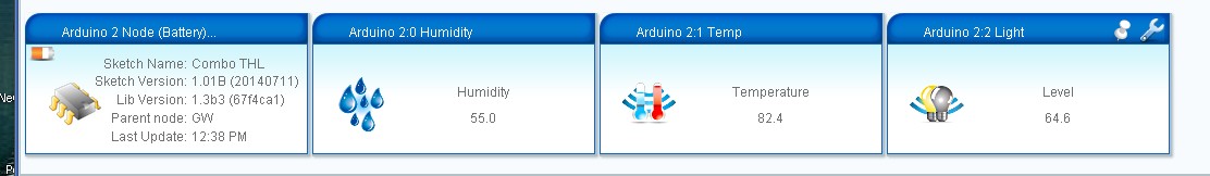
      When inclusion ran it found 4 new devices (I assume Node, Temp, Hum, Light)

      But Vera does NOT display the new devices even after multiple restarts. The Serial Monitor on the Sensor shows that it is indeed sending data and receiving ACK OK from the Gateway. Subsequent attempts at Inclusion do not find any devices so the GW at least knows they are there.

      Looking at the SysLog there is no sensor data being reported since I started this so apparently it isn't getting through.

      I'm going to Clear EEPROM again and fallback to the Temp/Hum sensor in case there is a problem with the new sensor code.

      Well, that's interesting. After reverting to he 2 sensor node Inclusion found 3 new devices and Vera now displays them. Yet when the 3 sensor code was running the serial monitor showed transmission and ACK for all three sensors. Now I'm confused.

      [UPDATE]
      I sorted it out, i had several problems.

      1. It appears the it is necessary to RESET the Node prior to Inclusion. Vera will then find the devices and display them. Absent the Reset it looks like Vera found them but that was all.
      2. When it finally displayed the LIGHT, it was showing as an ON/OFF Switch not a level. In the Setup routine i had
        gw.sendSensorPresentation(CHILD_ID_LIGHT, S_LIGHT);
        rather than
        gw.sendSensorPresentation(CHILD_ID_LIGHT, S_LIGHT_LEVEL);
        and similarly in the sending of the data I had left off the "_LEVEL" not realizing that that told the GW how to display the device. Now I know 🙂

      Anyway, the three input sensor is working. In the process of making the conversion I changed the Light Level to a floating number for consistency on the display .I've also implemented a simple Keepalive; every "N" times through the loop it resends the last temperature reading. i have this set to 30 times (and I adjusted the basic data cycle from 30 seconds to 60 seconds) so the keep alive occurs every 30 minutes whether the sensor sends any data in that time or not.

      posted in Development
      clippermiami
      clippermiami
    • RE: Lost USB/Serial Port Connection on Vera 3 AGAIN

      Thanks to all. @jribera's power sequence actually makse some sort of obtuse sense in the world of Vera 🙂

      I ended up by tackling the Ethernet Gateway project I had on hold. Late last week I received the iBoard I ordered to use for the gateway (see http://forum.mysensors.org/topic/224/iboard-cheap-single-board-ethernet-arduino-with-radio ).

      I'd planned on working on it sometime in the next few weeks. But since I was already off the air I figured I'd just jump in and get it done. I had it up and running in under an hour.

      posted in Vera
      clippermiami
      clippermiami
    • Calibrating Humidty

      For those who are interested in such things, you can calibrate the humidity sensor as follows:

      1. in a small bottle/jar cap place a teaspoon of ordinary salt.
      2. Put enough water on the salt to make it a paste
      3. Place the cap in the bottom of a "Ziplock" plastic bag
      4. Suspend the humidity sensor element (preferably just the element, not all the other electronics) at the top of the bag and seal it
      5. Wait about 12 hours, the humidity in the bag will reach 75% and your sensor should report accordingly

      I did this with the "vanilla" humidity/temperature element, the DH11, and found that it reported within about 2%. I only had the one DH11 so this might not be true of all of them.

      posted in General Discussion
      clippermiami
      clippermiami
    • RE: Antenna 101

      @Damme
      After your discussion of the antenna It occurred to me that the one thing I had not changed was the GW radio. I had one spare NRF24L01+PA+SMA so I swapped it in the GW. That appears to be the fix --- I can now see the sensor module all the way out in the yard at the far end of the house, through outside walls and a half dozen interior walls. I doubt i'll get the ~450 meters you describe but its a LOT better than the 10 feet I was getting 🙂

      I've found a NRF24L01 without the PA but with a SMA antenna so I think i'll see about adopting that for the sensors, especially the battery sensors. No amplifier but it is a 2-3 dBi antenna and every little dBi helps 🙂

      posted in Hardware
      clippermiami
      clippermiami
    • Battery Sensor v 1.0 PCB

      Previously I reported that I was working on developing a PCB for battery operated sensors to meet the following criteria:

      • Powered by CR123 3v Lithium Battery
      • 0.8v > 3.3v converter/regulator for max battery life
      • Support for 2@ Digital, 2@ Analog, 1@ L2C interface
      • Screw terminal blocks for sensor attachment

      The v1.0 PCB came back from OSHPark yesterday and I've installed all the parts and loaded a known working Temp/Humidity/Light sketch with the addition of the battery level reporting as described on My Sensors.

      I'm pleased to report that it installed and operated the first time and my VeraLite located and included it without a problem. I do have a problem with the battery voltage information and suspect I swapped the 1M Ohm and 470K Ohm resistors the voltage divider.

      It's a very spacious board ... for my first attempt at Eagle and PCB design and creation I chose not to try to conserve real estate but rather give myself plenty of room to work. I also have a minor component placement problem with the space allocated for the voltage divider resistors.

      I'm considering a version 2.0 board to correct the few errors and to include some other functions to make the board more general purpose battery or external power:

      • 2.1mm barrel connector and 7805 regulator for external power
      • 1v > 5v converter to allow 5v sensors on the battery version
      • 5 pin screw terminal blocks to support both 3.3 and 5 v sensors on any version

      I will make the current v 1.0 version available on OSHPark if anyone is interested.

      I have attached some photos of the board, components and the assembly. Everything is in sockets for this test but in production I'd probably solder the subassemblies directly to the board20140711_101852.jpg 20140711_101639.jpg 20140711_101629.jpg 20140711_101603.jpg 20140711_101515.jpg 20140711_101501.jpg 20140711_101449.jpg 20140711_101424.jpg 20140711_101407.jpg 20140711_114308.jpgScreenHunter_127 Jul. 11 12.39.jpg

      posted in My Project
      clippermiami
      clippermiami
    • Frustration ??

      I think I've discovered the most frustrating thing about this whole MySensor effort ... finding boxes to put the things in 🙂 Just when I think I've solved it, i find the box is too tall or too short or too narrow 🙂

      Absent a 3D printer ... 🙂

      posted in Enclosures / 3D Printing
      clippermiami
      clippermiami