Wow @Nicklas-Starkel congrats, that sounds great! And thanks for the feedback. Would you mind sharing your setup?
Regards, Edi
Posts made by eiten
-
RE: Long time test done with soil sensor!
-
RE: Forum Search not working?
@kamilb85 said in Forum Search not working?:
No, search is not working
Confirmed, it's not working for me either...
-
RE: 2x BME 280 on 2x arduino nano hangs in HomeAssistant
Well, I can only imagine that they try to send at the same time. Did you try with slightly different interval times?
-
RE: 2x BME 280 on 2x arduino nano hangs in HomeAssistant
Hello @HJ_SK
Could you please post the whole sketch in code tags or as an attachement?
Does it work stable with just one sensor node?
Could you#define MY_DEBUG
, attach at least one sensor to a PC and post the log after they hang?Regards, Edi
-
RE: Where to change settings?
Hey @OldSurferDude
I think we have a missunderstanding here. I have my gateways running on ESP32. When I add the integration I can enter the IP in this dialog:
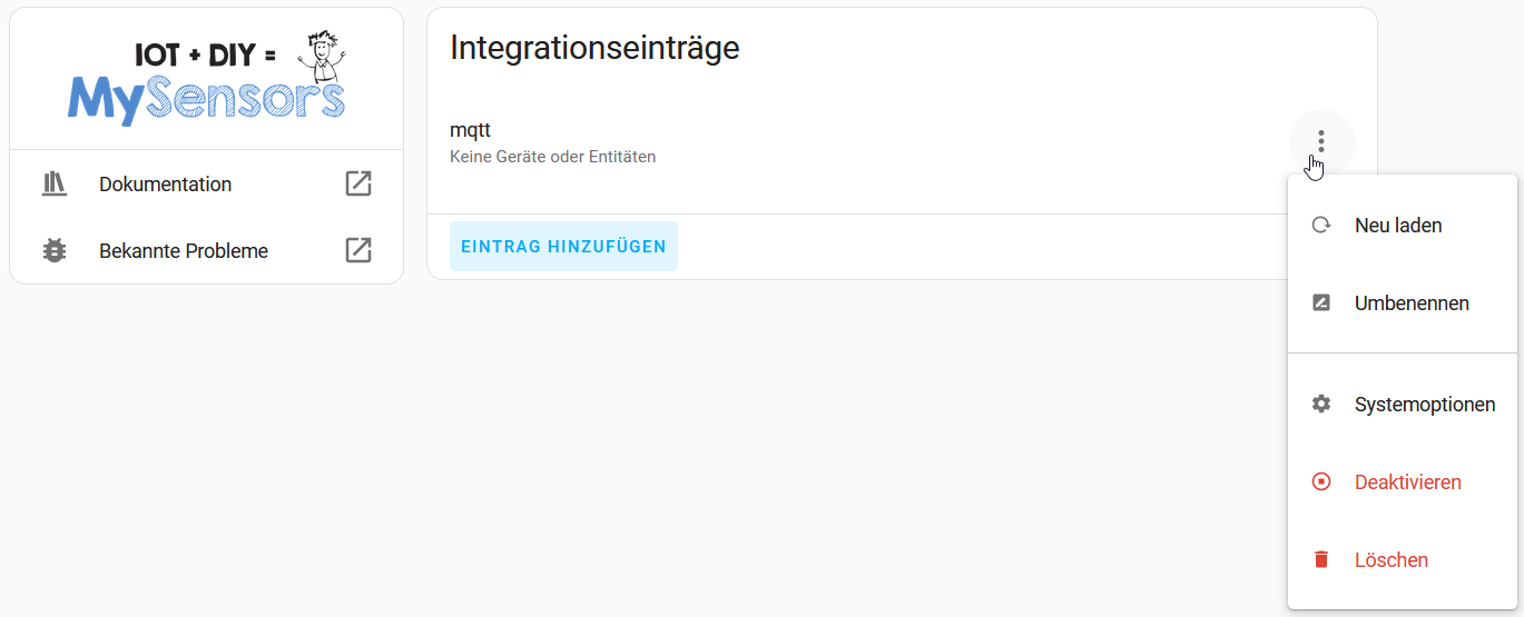
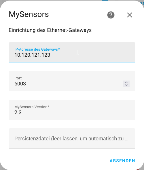
If you want to change the IP number of the gateway (or the MQTT topic or the serial port), there is no way to do this:
-
RE: Suddenly a Sensor is Missing, not the whole Node. (RPI Eth Gateway, HA)
Sorry @se-O-matic , but I can't see any problem. Does the temperature recover with time? I only can imagine that you have a collision on air.
-
RE: Suddenly a Sensor is Missing, not the whole Node. (RPI Eth Gateway, HA)
Hi @se-O-matic
can you please post your source code of the node in question?
You only restarted Home Assistant, not the nodes, correct?Thanks and regards, Edi
-
RE: Where to change settings?
Hey @OldSurferDude
thanks for the info. But I want to know where I can change the IP of the MySensors-TCP-Gateway.
Regards, Edi
-
RE: MQTT GW on ESP8266 supporting SSL/TLS?
@bgunnarb Thank you for your feedback. I'm very happy that I could help you. And thank you very much for the beer.
-
RE: MQTT GW on ESP8266 supporting SSL/TLS?
@bgunnarb are you on the master or de development branch? In the development brancht, TLS is implemented (check out this) :
/* * Modified by Eric Grammatico <eric@grammatico.me> * * Added support to secured connexion to mqtt server thanks to WiFiClientSecure class. * Please see comments in code. You can look for WiFiClientSecure, MY_GATEWAY_ESP8266_SECURE, * MY_MQTT_CA_CERT, MY_MQTT_FINGERPRINT and MY_MQTT_CLIENT_CERT in the code below to see what has * changed. No new method, no new class to be used by my_sensors. * * The following constants have to be defined from the gateway code: * MY_GATEWAY_ESP8266_SECURE in place of MY_GATEWAY_ESP8266 to go to secure connexions. * MY_MQTT_CA_CERTx Up to three root Certificates Authorities could be defined * to validate the mqtt server' certificate. The most secure. * MY_MQTT_FINGERPRINT Alternatively, the mqtt server' certificate finger print * could be used. Less secure and less convenient as you'll * have to update the fingerprint each time the mqtt server' * certificate is updated * If neither MY_MQTT_CA_CERT1 nor MY_MQTT_FINGERPRINT are * defined, insecure connexion will be established. The mqtt * server' certificate will not be validated. * MY_MQTT_CLIENT_CERT The mqtt server may require client certificate for * MY_MQTT_CLIENT_KEY authentication. * */
Regards, Edi
-
RE: GatawayESP8266 - Compile error
Hi everyone
Which MySensors lib did you use? The 2.3.2 or the delevopment version? I tried to fix the errors, but they don't appear in the development branch. Only another error which i fixed.
Regards, Edi
-
RE: GatawayESP8266 - Compile error
@OldSurferDude said in GatawayESP8266 - Compile error:
It appears that MySensors, too, is losing adherents.
Sad but true, it seems. I'm fighting myself out of a depression, but when I'm a little better, I'll try to fix the ESP8266 support in MySensors.
Regards, Edi
-
RE: GatawayESP8266 - Compile error
hey @OldSurferDude as I wrote in https://forum.mysensors.org/topic/12217/gateways/2?_=1707229400694, it is limited to 2 controllers. The esp8266 can handle many nodes. I had one with 9 or 10 IIRC. Now I got a ESP32 handling 39 nodes without any proplems.
-
RE: Gateways
@OldSurferDude well, the ESP8266 is limited to 4 TCP clients in arduino IDE. This can't be really increased. I did som experiments and you can set it up to 15, but after the 5th client on my web server, I got a freeze.
Maybe you got something wrong.
#define MY_GATEWAY_MAX_CLIENTS 2
defines how many controllers (eg Home Assistant) can connect to the gateway, not how many sensors/MySensors devices.And yes, you can have multiple TCP gateways in HomeAssistant. I got an NRF24, an RFM95 long range and a RFM95 short range gateway (all based on ESP32) on the same Home Assistant.
Regards, Edi
-
RE: single-click, double-click, long-press button possible with MySensors?
hey @dirkc, maybe you can trigger your interrupt to rising and falling edge and use millis() to see how long the press was?
-
RE: "Remote Irrigation with LoRaWAN: LM27313 Challenges and PCB Design"
@wrendral said in "Remote Irrigation with LoRaWAN: LM27313 Challenges and PCB Design":
I will go with a Li-Po Battery type: 304048 3.7V 1200mAh
Might work, but maybe the internal protection will trigger with the high current peaks. I'd suggest you plan a 0 Ohm, (2512/THT) resistor as R2 and then replace it with a 100Ohm/1Watt if the protection triggers.
-
RE: "Remote Irrigation with LoRaWAN: LM27313 Challenges and PCB Design"
@wrendral btw: what battery are you using?
-
RE: "Remote Irrigation with LoRaWAN: LM27313 Challenges and PCB Design"
Hey @wrendral
I don't have personal experience with the LM27313 I have to admit. But according to the data sheet, the device has cycle by cycle current limiting and thermal shutdown (see last sentence in Chapter 3). So I think regarding the switcher, you don't have problems. If the battery survives about 6 Amps for a short time after switch on, this should work very well without the 100 Ohm resistor.
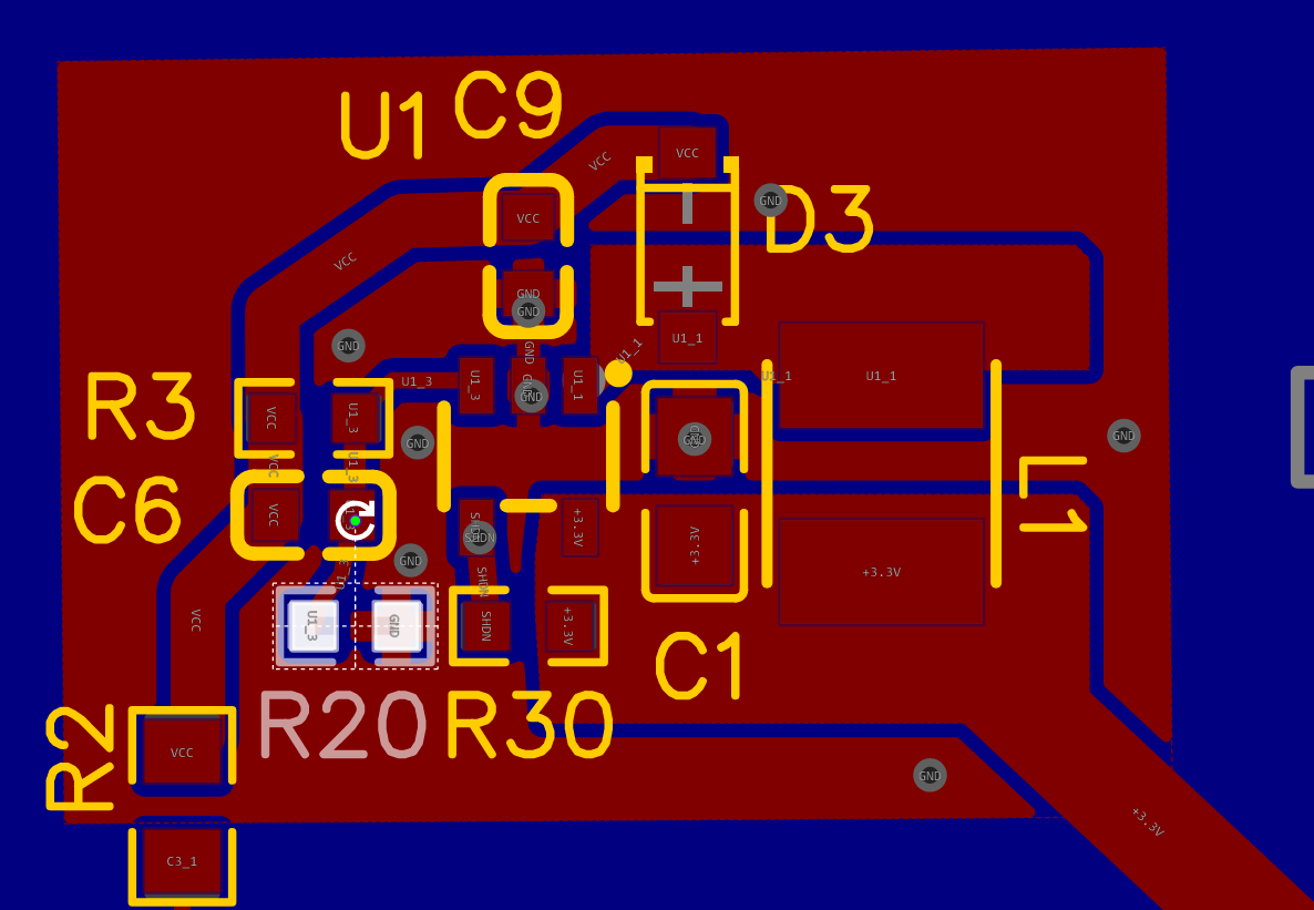
Regarding design: You have to make sure your switched current loops are as small as possible. So keep U1.5 - L1 - U1.1, U1.1 - D3 - U1.2 and U1.5 - C1 - U1.2 as short as possible.
I see you did a good job in your layout regarding this point.
What concerns me is the 3.3V connection to the LM27313 . There, you can have several amps of current, especially when switching on the LM, charging the capacitors. Let's say the LM limits the current to 1.5A on the 9 Volt side, then you have (including losses of the converter) about 4.5 Amps on the 3.3 V side. They have to go trough the 3.3V regulator on the Heltec board. I don't think it will survive it. And you have additional losses: Suppose you have a fully charged LiPo with 4.2 Volts. The regulator will first drop it to 3.3V, resulting in (4.2-3.3)V = 0.9V drop, 0.9V * 4.5A is over 4 Watt of thermal dissipation in the 3.3V regulator. I'd suggest you make a connection battery -> pcb, and from there a connection to the LM with MUCH wider traces than your 3.3V traces are now and another connection from the PCB to the Heltec battery pins.
Furthermore, I would add another ground plane on the top side, at least around the LM. Your ground traces are really to small there. See Figure 22 in the datasheet.
VCC also seems to be a bit thin.
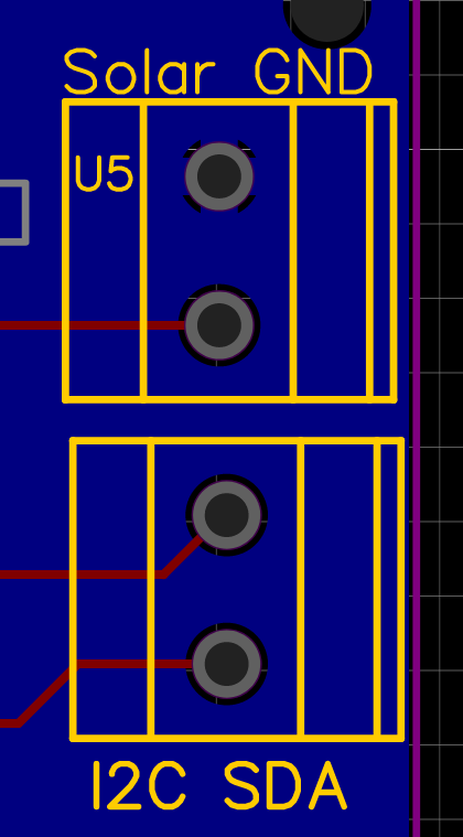
I'd put the comments for the connectors on the silkscreen layer, It's much better readable.Regards, Edi
-
RE: Saving last known good state, but not in EEPROM
When you define a utility meter in home assistant, you can choose the last option: regular reset or something like this (my installation is in german, it says "Regelmässiges Zurücksetzen". If you activate this, the utility meter continues counting when the counter of the measuring device is reset to zero.
-
RE: "Remote Irrigation with LoRaWAN: LM27313 Challenges and PCB Design"
@wrendral said in "Remote Irrigation with LoRaWAN: LM27313 Challenges and PCB Design":
'Rain Bird 100 DV 1'' M 9V'
Hi @wrendral
Ah, I see. I don't find any useful information about this latching type on the internet. So guessing from the name and according to your informations, this valve needs a 100mS pulse, 9V @1.5A to switch on or off?
For the passive components around the LM27313, I'd reccomend to use the TI webbench (google for it), there you can enter your parameters and get a design proposal.
The problem might be the current you need for this short time. THe LM27313 can deliver at most 1A, and I don't know what your battery can deliver, but I don't think it's in the range of 5A. So you need a rather big capacitor after the LM27313. You can estimate it if you know what maximum voltage drop during the impulse your valve can accept, I could not find informations regarding this.
About the PWM: please ignore my remark, I had the wrong part in my mind. This driver has an internal boost and does not need PWM to bootstrap the Vgs.
Regards, Edi
-
RE: Gateway on Raspberry pi 1
@mimaret It was a pleasure. Thank you for your feedback!
-
RE: Gateway on Raspberry pi 1
@mimaret said in Gateway on Raspberry pi 1:
I still have a little problem with the relays that I don't see in HA.
That's might be the problem I also had when I started with HA: In the first run of the loop, you have to send the state of every sensor you got. Else, HA will not see the sensor which did not send their state. It's not very obvious in the documentation, check 2. in this link.
Post your sketch if you need help. -
RE: "Remote Irrigation with LoRaWAN: LM27313 Challenges and PCB Design"
Hi @wrendral
Maybe you should provide a little bit more Info about your Project:
- You write about autonomy. Is this battery powered? What kind of battery (chemistry, capacity, voltage)
- What are your solenoid needs? Voltage and current?
- If so, you write that you use a solenoid valve. In my experience, they are not so well suited for battery powered applications for several reasons:
- If you are battery powered, normaly you don't have a pump and your pressure is low. Solenoid valves need some pressure to work
- For irrigation, you want to deliver low rates of water during a longer time (like one to two hours) so the soil gets everything and you don't have to much evaopration. This leads to
- Solenoids need current all the time they are on and so drain the battery
For this reasons, I switched to motorized ball valves for my remote, solar powered irrigation projects.
If you want to stay with your solenoid, I don't think that you need a H-Bridge, as your solenoid does not need negative voltages. Also, the DRV8837 does not fit because it needs a PWM, switching on and off all the time. I made good experience with high side switches like the Infinion PROFET series. They also include short circuit detection and other things.
Maybe you write more about your requirements and then we could help you to find a solution that suits you best.
Regards, Edi
BTW: I'm very glad to hear you use the HTCC-AB01. I wrote the MySensors integration for the ASR6501 and never got real feedback. Someone is using it! YEAH! -
RE: Gateway on Raspberry pi 1
@mimaret said in Gateway on Raspberry pi 1:
I thought about MQTT, but in the options I don't see User and Password for MQTT.
It's
MY_MQTT_USER
andMY_MQTT_PASSWORD
, check out here.EDIT: sorry, for the raspberry configure script, this is relevant:
--my-mqtt-client-id=<ID> MQTT client id. --my-mqtt-user=<UID> MQTT user id. --my-mqtt-password=<PASS> MQTT password.
-
RE: Gateway on Raspberry pi 1
@mimaret said in Gateway on Raspberry pi 1:
stropts.h
stropts.h is part of the Posix STREAMS extension, which Linux never supported. (Since 2008, it has also been marked as obsolescent by Posix, so it may be removed in some future standard revision.) In Debian, it was removed in the bullseye release.
Get the development branch of MySensors, there it's not used anymore.HTH, Edi
-
RE: Home Assistant update changed USB port name
What I did not try but might work: copy your persistence file, delete the old GW and create a new one with the persistence file you copied. Maybe the devices are preserved like this. Maybe you should create a full backup before...
<edit: typo>
-
RE: Home Assistant update changed USB port name
Yes, but it's dangerous to go there:
MAKE A BACKUP OF/homeassistant/.storage/core.config_entries
Open the original file and search for your GW ("domain": "mysensors"
). There you can edit your settings. Be carefull to not touch anything else!
It's a good practice to use the symlink in/dev/serial/by-id/
instead of the device under/dev/serial
as this is not as likely to change.Regards, Edi
-
RE: Can not compile on Arduino Nano ESP 32
That's strange. Is it exactly the code from above? It seems, it is in gateway mode, but in your sketch, you commented out the gateway option...
-
RE: Can not compile on Arduino Nano ESP 32
OK, so I suppose the build flags are incorrect. Do you use PlatformIO? Then, you could try:
build_flags = -D ARDUINO_USB_MODE=1 -D ARDUINO_USB_CDC_ON_BOOT=1
If you are on the Arduino IDE, you have to set
Tools -> USB-Mode -> CDC-Mode
. Ore something similar, I don't have the Arduino IDE installed ATM. IIRC, monitor speed must be set to 460800. -
RE: Gateway stops communicating (again)
Hm, maybe the problem is that your rPI has a short interruption in the WIFI connection, the MQTT TCP connection is interrupted and does not autostart again. Maybe there is something in the logs. Maybe you can find something about reconnects in one of these:
journalctl --unit=systemd-networkd journalctl --unit=wpa_supplicant
You could try to run wpa_cli in daemon mode to react to disconnects and connects. Create a script like this:
#!/bin/bash case "$2" in CONNECTED) <your command to start the gateway>; ;; DISCONNECTED) <your command to stop the gateway>; ;; esac
then, start
wpa_cli
in deamon mode:wpa_cli -a /path/to/your/script #use sudo if your gateway commands need sudo
If that helps, you could create a service from this command.
Regards, Edi
-
RE: FOTA using OptiBoot copy_flash_pages
IT WORKS
I got a first working version, using an ATmega1284P running on MightyCore 2.2.2 (as soon as I began developement, they switched from Optiboot to Urboot in version 3.0.0, whicht does not include the copy_flash_pages function anymore, but I'm working on a work around there).
Only thing I could not solve is to do a CRC check of the image after download...
You can try it out here: https://github.com/eiten/MySensors/tree/FOTAInternalFlashTest
It's not beautiful yet with much Serial.prints in it, but maybe it helps you if you find errors.
-
RE: Radio RFM95 does not send ATmega1284p
Don't ask me why, but now it works. I changed nothing! Went to my girl over the weekend, coming back, the node was registred. Maybe a jammer went away?
-
Radio RFM95 does not send ATmega1284p
Hello everyone,
first, I already made several working designs with RFM95 and ATmega328pb with exactly the same antenna design.
Now I made two developement PCBs with an ATmega1284p and a RFM95 module. Communication MCU <-> radio seems to work, but I can't see any communication on the GW side (there are serveral other nodes connected to that GW, so it works).__ __ ____ | \/ |_ _/ ___| ___ _ __ ___ ___ _ __ ___ | |\/| | | | \___ \ / _ \ `_ \/ __|/ _ \| `__/ __| | | | | |_| |___| | __/ | | \__ \ _ | | \__ \ |_| |_|\__, |____/ \___|_| |_|___/\___/|_| |___/ |___/ 2.4.0-alpha 18 MCO:BGN:INIT NODE,CP=RLNNA---,FQ=8,REL=1,VER=2.4.0-alpha 28 TSM:INIT 30 TSF:WUR:MS=0 32 RFM95:INIT 32 RFM95:INIT:PIN,CS=3,IQP=12,IQN=65535 49 RFM95:PTX:LEVEL=13 51 TSM:INIT:TSP OK 53 TSM:FPAR 55 RFM95:SWR:SEND,TO=255,SEQ=0,RETRY=0 7061 ?TSF:MSG:SEND,255-255-255-255,s=255,c=3,t=7,pt=0,l=0,sg=0,ft=0,st=NACK: 9070 !TSM:FPAR:NO REPLY 9072 TSM:FPAR 9074 RFM95:SWR:SEND,TO=255,SEQ=1,RETRY=0 16080 ?TSF:MSG:SEND,255-255-255-255,s=255,c=3,t=7,pt=0,l=0,sg=0,ft=1,st=NACK: 18092 !TSM:FPAR:NO REPLY 18094 TSM:FPAR 18096 RFM95:SWR:SEND,TO=255,SEQ=2,RETRY=0
I used a very basic programm:
#define MY_RADIO_RFM95 #define MY_DEBUG_VERBOSE_RFM95 #define MY_DEBUG_VERBOSE_CORE #define MY_DEBUG_VERBOSE_TRANSPORT #define MY_DEBUG //#define MY_RFM95_FREQUENCY (869400000ul) #define MY_RFM95_IRQ_PIN PIN_PB2 #define MY_RFM95_CS_PIN PIN_PD3 #include <Arduino.h> #include <MySensors.h> void setup() { } void loop() { }
Can anyone spot a stupid mistake I made?
Thanks, Edi
-
RE: can't make getStream() work
@Mizar03 sorry for the late response.
getStream()
only works for firmware transfers. I'd suggestgetString()
, this should also work for all types of payloads, as they are normaly ASCII and not binary data. -
RE: Can not compile on Arduino Nano ESP 32
@ctodor of course:
https://github.com/mysensors/MySensors/tree/development does contain sleep code for ESP. You can download the library here as a zip file. -
RE: Can not compile on Arduino Nano ESP 32
As an additional info, sleep will not work on the ESP in version 2.3.2. Try the developement branch from the github if you need sleep, there I implemented this.
-
RE: Can not compile on Arduino Nano ESP 32
Your board seems to use USBCDC to communicate with the PC. So in the file
/hal/architecture/ESP32/MyHwESP32.cpp
, line 30, you have to changeMY_SERIALDEVICE.begin(MY_BAUD_RATE, SERIAL_8N1);
toMY_SERIALDEVICE.begin(MY_BAUD_RATE);
.
Furthermore, as ESP32 implements the functionsleep(uint32_t)
iself, you need to change line 147 in the sketch fromsleep(SLEEP_TIME);
tosleep(SLEEP_TIME, false);
.Hope this helps!
Regards, Ei
-
RE: Best VOC sensor for detecting a wide range of VOC's?
@NeverDie said in Best VOC sensor for detecting a wide range of VOC's?:
So, I guess what I'm looking for is a sensor that's sensitive to a wide assortment of VOCs. Any recommendations?
Well, I play around with the BME680. It is currently in my office. The problem is, that Bosch makes a big secret of how it works exactly. It seems that it lerns about the "normal" quality of the air over time and then reacts to changes of that standard.
It takes about 12h for the status to go from 1 to 0. After this time, when placed close to a window, the status goes back to 0 after opening the window for a short time for several days.
In the office here it seems to work. It changes status when the girl form the HR department is standing close to itBut to be honest, the IAQ there is as far as I can judge this, only calculated based on temperature, pressure and humidity?
If you find something good, please inform us
-
FOTA using OptiBoot copy_flash_pages
Hello everyone,
as a challenge, I want to try to implement FOTA using the OptiBoot copy_flash_pages to MySensors. The reason is that need a little more flash to implement LoRaWAN on my climate sensors that are not close enough to a MySensors gateway, so I'll do it with a ATmega644P or (for some reasons cheaper on LCSC) a ATmega1284P. As there is more of half the flash available when they run on MySensors, I see it as a challenge to implement FOTA without an additional I2C flash chip.
I'll use this thread as a blog to show and discuss my progress with you. If you are not interested, let me know, so I won't bother you further.
As a start, I ordered two PCBs from LCSC. A CPU PCB for a ATmega1284P or ATmega664P, and a PCB for the radio (and a Flash chip, but this is for some other project). I'll try to attach the schematics. I'll keep you updated as soon as they arrive.Regards!
Edit: PDF did not work, so here are some PNGs:
-
RE: MYSBootloader + STM32 with Ethernet module
I'm afraid, the MYSbootloader is only available for the AVRs.
-
RE: Send 2x relay states to Home Assistant to make them visible?
@Matt Yes, the landscape there is incredible. Unfortunately, I mostly have to work when I'm there
Where are you from? -
RE: Send 2x relay states to Home Assistant to make them visible?
Ah that's good.
Yes, bring the battery inside over winter. For my all year outdoor thingies, I changed now to SoIon, let's se how they do in cold times.
Ah cool! Did you ride the train? If so, you rode on my work, I do electrical engineering for cog wheel trains! -
RE: Send 2x relay states to Home Assistant to make them visible?
Hey Matt, no problem, that's what the community is here for. But if we meet, I'd love to have a beer with you! I'm from switzerland, so chances may not be too high.
Some other thoughts:
For SLA, you can estimate the SOC by measuring the voltage, but only if you have no load an no charging. If you want to do it really good, you also take the non-linearity into account. The SLA is full, if the open circuit voltage (no load, no charging) is at about 12.8V. 11V for empty is ok. But I would add some code that the relays don't switch if you are under 11V or so, because this can damage the battery.Do you use a charger, or is the panel directly connected to the battery? In the second case, you should add a diode so the battery does not reverse feed the panel when it's dark. And you should switch of (short circuit) the panel if the battery voltage is at 14.4V or above. This will also help for a longer battery life.
-
RE: Send 2x relay states to Home Assistant to make them visible?
Hello again!
Turns out that:
- I suppose you are on an AVR. They don't seem to like
PSTR()
. I changed them toF()
and now there are no more hieroglyphs. - You have to send the sensor values before any other messages (in this case the
sendBatteryLevel(battPct);
for HA to be happy. - I forgot to set the
lastSend = now;
, so it repeatedly sent temp and batt. - I forgot to set
changeRelay1 = true;
andchangeRelay2 = true;
.
For me, it works now:
Here is the code:
// Configure MySensors #define MY_DEBUG #define MY_RADIO_RF24 // MY_RADIO_NRF24 is deprecated #define MY_RF24_PA_LEVEL RF24_PA_HIGH #define MY_REPEATER_FEATURE // Configure Firmware #define FW_NAME F("Relay+Temp") // Firmware name #define FW_VERSION F("2.0") // Firmware version #define MEASURE_INTERVAL (10 * 60 * 1000ul) // Measuring interval in ms #define CHILD_ID_TEMP (1) // Child ID temperature #define CHILD_ID_RELAY1 (2) // Child ID relay 1 #define CHILD_ID_RELAY2 (13) // Child ID relay 2 #define CHILD_ID_BATT (4) // Child ID battery voltage #define ONE_WIRE_BUS_PIN (3) // OneWire bus pin #define RELAY1_PIN (4) // DIO of relay 1 #define RELAY2_PIN (5) // DIO of relay 2 #define BATT_SENSE_PIN (A0) // Analog pin for battery voltage #define BATT_MAX_V (14.5) // Battery maximum voltage #define BATT_MIN_V (11.0) // Battery minimum voltage #define BATT_LSB_VALUE (0.0139644) // Battery LSB voltage #define RELAY_ON HIGH // GPIO state for relay ON #define RELAY_OFF LOW // GPIO state for relay OFF // Includes #include <MySensors.h> #include <DallasTemperature.h> // Globals OneWire oneWire(ONE_WIRE_BUS_PIN); // OneWire bus DallasTemperature sensors(&oneWire); // Temperature Sensors MyMessage msgTemp(CHILD_ID_TEMP, V_TEMP); MyMessage msgRelay1(CHILD_ID_RELAY1, V_STATUS); MyMessage msgRelay2(CHILD_ID_RELAY2, V_STATUS); MyMessage msgBatt(CHILD_ID_BATT, V_VOLTAGE); uint32_t lastSend = -MEASURE_INTERVAL; // When did we last send temperature and voltage? // We set it to -MEASURE_INTERVAL in case first send goes wrong it will be retried bool firstRun = true; // Are we in the first loop? Used to send inital values of all sensors uint32_t conversationTime; // ms the sensor needs after measure command bool changeRelay1 = true; // State of relay 1 changed bool changeRelay2 = true; // State of relay 2 changed void before() { // set relay pins as output and switch of relays pinMode(RELAY1_PIN, OUTPUT); pinMode(RELAY2_PIN, OUTPUT); digitalWrite(RELAY1_PIN, RELAY_OFF); digitalWrite(RELAY2_PIN, RELAY_OFF); } void setup() { analogReference(INTERNAL); // Use internal Vref sensors.begin(); // start DS temperature sensors sensors.setWaitForConversion(false); // Do not wait for converstation to finish // Get the conversation time here, so you don't need the time and ram for the // function call every loop. Yo don't change resolution, so this stays constant conversationTime = sensors.millisToWaitForConversion(sensors.getResolution()); } void presentation() { sendSketchInfo(FW_NAME, FW_VERSION); present(CHILD_ID_TEMP, S_TEMP, F("Air temperature")); present(CHILD_ID_RELAY1, S_BINARY, F("Relay 1")); present(CHILD_ID_RELAY2, S_BINARY, F("Relay 2")); present(CHILD_ID_BATT, S_MULTIMETER, F("Battery voltage")); } void loop() { uint32_t now = millis(); // Send relay state whenever they changed (or on first loop) if (changeRelay1 || firstRun) { bool relayState = (digitalRead(RELAY1_PIN) == RELAY_ON) ? true : false; send(msgRelay1.set(relayState)); changeRelay1 = false; #ifdef MY_DEBUG Serial.print(F("Sent relay 1 status: ")); Serial.println(relayState ? F("ON") : F("OFF")); #endif } if (changeRelay2 || firstRun) { bool relayState = (digitalRead(RELAY2_PIN) == RELAY_ON) ? true : false; send(msgRelay2.set(relayState)); changeRelay2 = false; #ifdef MY_DEBUG Serial.print(F("Sent relay 2 status: ")); Serial.println(relayState ? F("ON") : F("OFF")); #endif } // Temperature and battery voltage are sent only every MEASURE_INTERVAL ms // or if it is the first run of the loop, as HA else does not show them if (firstRun || (now - lastSend > MEASURE_INTERVAL)) { // Trigger temperature measurement and wait for it to finish. Use wait() // and not delay so you don't miss incoming relay commands during this time // and keep the repeater function working sensors.requestTemperatures(); wait(conversationTime); // Get the temperature in °C to check if it is valid float temperature = sensors.getTempCByIndex(0); // If temperature is valid, process and send it temperature = 12.55; if (temperature != -127.0 && temperature != 85.0) { // Get imperial units if controller is not set to metric system if (!getControllerConfig().isMetric) { temperature = sensors.getTempFByIndex(0); } // round to one digit temperature = static_cast<float>(static_cast<int>(temperature) * 10.) / 10.; send(msgTemp.set(temperature, 1)); #ifdef MY_DEBUG Serial.print(F("Sent temperature: ")); Serial.print(temperature); Serial.println(getControllerConfig().isMetric ? F("C") : F("F")); #endif } float battVolt = analogRead(BATT_SENSE_PIN) * BATT_LSB_VALUE; int battPct = static_cast<int>(((battVolt - BATT_MIN_V) / (BATT_MAX_V - BATT_MIN_V)) * 100.); battPct = constrain(battPct, 0, 100); // Avoid battery percentage outside 0-100% sendBatteryLevel(battPct); send(msgBatt.set(battVolt, 2)); #ifdef MY_DEBUG Serial.print(F("Sent battery status: ")); Serial.print(battVolt, 2); Serial.print(F("V, ")); Serial.print(battPct); Serial.println("%"); #endif lastSend = now; } firstRun = false; // after the first loop, set firstRun to false; } void receive(const MyMessage &message) { #ifdef MY_DEBUG Serial.print(F("Incomming message: ")); #endif // V_STATUS messages are expected for relay commands if (message.type == V_STATUS) { // Check which relay should be switched switch (message.sensor) { case CHILD_ID_RELAY1: digitalWrite(RELAY1_PIN, message.getBool() ? RELAY_ON : RELAY_OFF); changeRelay1 = true; #ifdef MY_DEBUG Serial.print(F("switched relay 1 ")); Serial.println(message.getBool() ? F("ON") : F("OFF")); #endif break; case CHILD_ID_RELAY2: digitalWrite(RELAY2_PIN, message.getBool() ? RELAY_ON : RELAY_OFF); changeRelay2 = true; #ifdef MY_DEBUG Serial.print(F("switched relay 2 ")); Serial.println(message.getBool() ? F("ON") : F("OFF")); #endif break; default: #ifdef MY_DEBUG Serial.print(F(" unknown child ID ")); Serial.println(message.sensor); #endif } } else { #ifdef MY_DEBUG Serial.print(F(" unknown message type ")); Serial.println(message.type); #endif } }
And the monitor output (Link to the log parser) :
__ __ ____ | \/ |_ _/ ___| ___ _ __ ___ ___ _ __ ___ | |\/| | | | \___ \ / _ \ `_ \/ __|/ _ \| `__/ __| | | | | |_| |___| | __/ | | \__ \ _ | | \__ \ |_| |_|\__, |____/ \___|_| |_|___/\___/|_| |___/ |___/ 2.3.2 16 MCO:BGN:INIT REPEATER,CP=RNNRA---,FQ=8,REL=255,VER=2.3.2 28 MCO:BGN:BFR 30 TSM:INIT 30 TSF:WUR:MS=0 38 TSM:INIT:TSP OK 40 TSF:SID:OK,ID=1 43 TSM:FPAR 47 ?TSF:MSG:SEND,1-1-255-255,s=255,c=3,t=7,pt=0,l=0,sg=0,ft=0,st=OK: 167 TSF:MSG:READ,0-0-1,s=255,c=3,t=8,pt=1,l=1,sg=0:0 174 TSF:MSG:FPAR OK,ID=0,D=1 2056 TSM:FPAR:OK 2056 TSM:ID 2058 TSM:ID:OK 2060 TSM:UPL 2066 TSF:MSG:SEND,1-1-0-0,s=255,c=3,t=24,pt=1,l=1,sg=0,ft=0,st=OK:1 2084 TSF:MSG:READ,0-0-1,s=255,c=3,t=25,pt=1,l=1,sg=0:1 2091 TSF:MSG:PONG RECV,HP=1 2093 TSM:UPL:OK 2095 TSM:READY:ID=1,PAR=0,DIS=1 2103 TSF:MSG:SEND,1-1-0-0,s=255,c=3,t=15,pt=6,l=2,sg=0,ft=0,st=OK:0100 2117 TSF:MSG:READ,0-0-1,s=255,c=3,t=15,pt=6,l=2,sg=0:0100 2125 TSF:MSG:SEND,1-1-0-0,s=255,c=0,t=18,pt=0,l=5,sg=0,ft=0,st=OK:2.3.2 2136 TSF:MSG:SEND,1-1-0-0,s=255,c=3,t=6,pt=1,l=1,sg=0,ft=0,st=OK:0 2177 TSF:MSG:READ,0-0-1,s=255,c=3,t=6,pt=0,l=1,sg=0:M 2185 TSF:MSG:SEND,1-1-0-0,s=255,c=3,t=11,pt=0,l=10,sg=0,ft=0,st=OK:Relay+Temp 2195 TSF:MSG:SEND,1-1-0-0,s=255,c=3,t=12,pt=0,l=3,sg=0,ft=0,st=OK:1.0 2215 TSF:MSG:SEND,1-1-0-0,s=1,c=0,t=6,pt=0,l=15,sg=0,ft=0,st=OK:Air temperature 2228 TSF:MSG:SEND,1-1-0-0,s=2,c=0,t=3,pt=0,l=7,sg=0,ft=0,st=OK:Relay 1 2242 TSF:MSG:SEND,1-1-0-0,s=13,c=0,t=3,pt=0,l=7,sg=0,ft=0,st=OK:Relay 2 2254 TSF:MSG:SEND,1-1-0-0,s=4,c=0,t=30,pt=0,l=15,sg=0,ft=0,st=OK:Battery voltage 2263 MCO:REG:REQ 2269 TSF:MSG:SEND,1-1-0-0,s=255,c=3,t=26,pt=1,l=1,sg=0,ft=0,st=OK:2 2279 TSF:MSG:READ,0-0-1,s=255,c=3,t=27,pt=1,l=1,sg=0:1 2285 MCO:PIM:NODE REG=1 2287 MCO:BGN:STP 2289 MCO:BGN:INIT OK,TSP=1 2297 TSF:MSG:SEND,1-1-0-0,s=2,c=1,t=2,pt=1,l=1,sg=0,ft=0,st=OK:0 Sent relay 1 status: OFF 2308 TSF:MSG:SEND,1-1-0-0,s=13,c=1,t=2,pt=1,l=1,sg=0,ft=0,st=OK:0 Sent relay 2 status: OFF 2357 TSF:MSG:READ,0-0-1,s=255,c=3,t=6,pt=0,l=1,sg=0:M 2428 TSF:MSG:SEND,1-1-0-0,s=1,c=1,t=0,pt=7,l=5,sg=0,ft=0,st=OK:12.0 Sent temperature: 12.00C 2441 TSF:MSG:SEND,1-1-0-0,s=255,c=3,t=0,pt=1,l=1,sg=0,ft=0,st=OK:0 2451 TSF:MSG:SEND,1-1-0-0,s=4,c=1,t=38,pt=7,l=5,sg=0,ft=0,st=OK:2.67 Sent battery status: 2.67V, 0% 18446 TSF:MSG:READ,0-0-1,s=13,c=1,t=2,pt=0,l=1,sg=0:1 18452 TSF:MSG:ECHO REQ 18458 TSF:MSG:SEND,1-1-0-0,s=13,c=1,t=2,pt=0,l=1,sg=0,ft=0,st=OK:1 Incomming message: switched relay 2 ON 18468 TSF:MSG:SEND,1-1-0-0,s=13,c=1,t=2,pt=1,l=1,sg=0,ft=0,st=OK:1 Sent relay 2 status: ON
- I suppose you are on an AVR. They don't seem to like
-
RE: Send 2x relay states to Home Assistant to make them visible?
No problem Matt, as I said, I had a looong train ride. Just got home, I'll try it myself now. May I ask you which controller you use?
And the battery type would also be interesting. Lead Acid? -
RE: Send 2x relay states to Home Assistant to make them visible?
Hi Matt,
try this one:
// Configure MySensors #define MY_DEBUG #define MY_RADIO_RF24 // MY_RADIO_NRF24 is deprecated #define MY_RF24_PA_LEVEL RF24_PA_HIGH #define MY_REPEATER_FEATURE // Configure Firmware #define FW_NAME PSTR("Relay+Temp") // Firmware name #define FW_VERSION PSTR("1.0") // Firmware version #define MEASURE_INTERVAL (10 * 60 * 1000ul) // Measuring interval in ms #define CHILD_ID_TEMP (1) // Child ID temperature #define CHILD_ID_RELAY1 (2) // Child ID relay 1 #define CHILD_ID_RELAY2 (3) // Child ID relay 2 #define CHILD_ID_BATT (4) // Child ID battery voltage #define ONE_WIRE_BUS_PIN (3) // OneWire bus pin #define RELAY1_PIN (4) // DIO of relay 1 #define RELAY2_PIN (5) // DIO of relay 2 #define BATT_SENSE_PIN (A0) // Analog pin for battery voltage #define BATT_MAX_V (14.5) // Battery maximum voltage #define BATT_MIN_V (11.0) // Battery minimum voltage #define BATT_LSB_VALUE (0.0139644) // Battery LSB voltage #define RELAY_ON HIGH // GPIO state for relay ON #define RELAY_OFF LOW // GPIO state for relay OFF // Includes #include <MySensors.h> #include <DallasTemperature.h> // Globals OneWire oneWire(ONE_WIRE_BUS_PIN); // OneWire bus DallasTemperature sensors(&oneWire); // Temperature Sensors MyMessage msgTemp(CHILD_ID_TEMP, V_TEMP); MyMessage msgRelay1(CHILD_ID_RELAY1, V_STATUS); MyMessage msgRelay2(CHILD_ID_RELAY2, V_STATUS); MyMessage msgBatt(CHILD_ID_BATT, V_VOLTAGE); uint32_t lastSend = -MEASURE_INTERVAL; // When did we last send temperature and voltage? // We set it to -MEASURE_INTERVAL in case first send goes wrong it will be retried bool firstRun = true; // Are we in the first loop? Used to send inital values of all sensors uint32_t conversationTime; // ms the sensor needs after measure command bool changeRelay1 = true; // State of relay 1 changed bool changeRelay2 = true; // State of relay 2 changed void before() { // set relay pins as output and switch of relays pinMode(RELAY1_PIN, OUTPUT); pinMode(RELAY2_PIN, OUTPUT); digitalWrite(RELAY1_PIN, RELAY_OFF); digitalWrite(RELAY2_PIN, RELAY_OFF); } void setup() { analogReference(INTERNAL); // Use internal Vref sensors.begin(); // start DS temperature sensors sensors.setWaitForConversion(false); // Do not wait for converstation to finish // Get the conversation time here, so you don't need the time and ram for the // function call every loop. Yo don't change resolution, so this stays constant conversationTime = sensors.millisToWaitForConversion(sensors.getResolution()); } void presentation() { sendSketchInfo(FW_NAME, FW_VERSION); present(CHILD_ID_TEMP, S_TEMP, PSTR("Air temperature")); present(CHILD_ID_RELAY1, S_BINARY, PSTR("Relay 1")); present(CHILD_ID_RELAY2, S_BINARY, PSTR("Relay 2")); present(CHILD_ID_BATT, S_MULTIMETER, PSTR("Battery voltage")); } void loop() { // Temperature and battery voltage are sent only every MEASURE_INTERVAL ms // or if it is the first run of the loop, as HA else does not show them uint32_t now = millis(); if (firstRun || (now - lastSend > MEASURE_INTERVAL)) { // Trigger temperature measurement and wait for it to finish. Use wait() // and not delay so you don't miss incoming relay commands during this time // and keep the repeater function working sensors.requestTemperatures(); wait(conversationTime); // Get the temperature in °C to check if it is valid float temperature = sensors.getTempCByIndex(0); // If temperature is valid, process and send it if (temperature != -127.0 && temperature != 85.0) { // Get imperial units if controller is not set to metric system if (!getControllerConfig().isMetric) { temperature = sensors.getTempFByIndex(0); } // round to one digit temperature = static_cast<float>(static_cast<int>(temperature) * 10.) / 10.; send(msgTemp.set(temperature, 1)); #ifdef MY_DEBUG Serial.print(PSTR("Sent temperature: ")); Serial.print(temperature); Serial.println(getControllerConfig().isMetric ? PSTR("C") : PSTR("F")); #endif } float battVolt = analogRead(BATT_SENSE_PIN) * BATT_LSB_VALUE; int battPct = static_cast<int>(((battVolt - BATT_MIN_V) / (BATT_MAX_V - BATT_MIN_V)) * 100.); battPct = constrain(battPct, 0, 100); // Avoid battery percentage outside 0-100% sendBatteryLevel(battPct); send(msgBatt.set(battVolt, 2)); #ifdef MY_DEBUG Serial.print(PSTR("Sent battery status: ")); Serial.print(battVolt, 2); Serial.print(PSTR("V, ")); Serial.print(battPct); Serial.println("%"); #endif } // Send relay state whenever they changed (or on first loop) if (changeRelay1 || firstRun) { bool relayState = (digitalRead(RELAY1_PIN) == RELAY_ON) ? true : false; send(msgRelay1.set(relayState)); changeRelay1 = false; #ifdef MY_DEBUG Serial.print(PSTR("Sent relay 1 status: ")); Serial.println(relayState ? PSTR("ON") : PSTR("OFF")); #endif } if (changeRelay2 || firstRun) { bool relayState = (digitalRead(RELAY2_PIN) == RELAY_ON) ? true : false; send(msgRelay2.set(relayState)); changeRelay2 = false; #ifdef MY_DEBUG Serial.print(PSTR("Sent relay 2 status: ")); Serial.println(relayState ? PSTR("ON") : PSTR("OFF")); #endif } firstRun = false; // after the first loop, set firstRun to false; } void receive(const MyMessage &message) { #ifdef MY_DEBUG Serial.print(PSTR("Incomming message: ")); #endif // V_STATUS messages are expected for relay commands if (message.type == V_STATUS) { // Check which relay should be switched switch (message.sensor) { case CHILD_ID_RELAY1: digitalWrite(RELAY1_PIN, message.getBool() ? RELAY_ON : RELAY_OFF); #ifdef MY_DEBUG Serial.print(PSTR(" switched relay 1 ")); Serial.println(message.getBool() ? PSTR("ON") : PSTR("OFF")); #endif break; case CHILD_ID_RELAY2: digitalWrite(RELAY2_PIN, message.getBool() ? RELAY_ON : RELAY_OFF); #ifdef MY_DEBUG Serial.print(PSTR(" switched relay 2 ")); Serial.println(message.getBool() ? PSTR("ON") : PSTR("OFF")); #endif break; default: #ifdef MY_DEBUG Serial.print(PSTR(" unknown child ID ")); Serial.println(message.sensor); #endif } } else { #ifdef MY_DEBUG Serial.print(PSTR(" unknown message type ")); Serial.println(message.type); #endif } }
I have to admit, I did not test it, but it compiles. I'm in the train ATM and do not have hardware. But I'll test it later.
To keep it simple there are things missing like resending and things like that.Regards, Edi
-
RE: Send 2x relay states to Home Assistant to make them visible?
Hi Matt,
you don't send the state of your relays at all! So you need to add
MyMessage msgRelay1(CHILD_ID_RELAY1, V_STATUS); MyMessage msgRelay2(CHILD_ID_RELAY2, V_STATUS);
objects. The presentation is OK. Then, you need a globale variable
bool firstRun=true;
before the
void loop()
.
Inside the loop, i would put it in the begining, you need aif (firstRun) { send(msgRelay1.set(digitalRead(RELAY_1)); send(msgRelay1.set(digitalRead(RELAY_1+1)); firstRun == false; }
But your code is too complicated, and setting is not handled in the receive. If you give me some minutes, I'll post you a complete example.
-
RE: Send timer program to pool filter controller
@Vasilis-Vlachoudis well, normally, I would realize this by a timer in HA and just sending the ON and OFF commands to the switch.
Alternatively, you could use a custom variable and use a format like this in your message:+0800-1000+1400-1900
. On your arduino, you need to write an interpreter for this format and see if your output matches the requirement of the current time frame.
If you want to controll it from the Arduino, be sure to often request time from the controller. I already got some cheep Arduino Nanos from Ali with a 1% clock accuracy... This may not sound like much but in worst case, this is a quarter of an hour per day!
Regards, Edi -
RE: Help me build a 6-light-sensor & 2 ch relay node.
Hi @airmedic79
I see several problems in your code. Here, you redefine RELAY_PIN:#define RELAY_PIN 3 // Arduino Digital I/O pin number for power relay (connected to D3) #define RELAY_PIN 4 // Arduino Digital I/O pin number for mode relay (connected to D4)
Its both times
RELAY_PIN
, the same name for the define, so you will end up withRELAY_PIN
equals 4. This should yield a warning.You never present the binary sensors, because in this line:
for (int sensor=1, pin=RELAY_PIN; sensor<=NUMBER_OF_RELAYS; sensor++, pin++) {
RELAY_PIN
is 4, andNUMBER_OF_RELAYS
is 2, so the for loop is never executed.
Also, I think you got a problem with your sensor IDs, i think id 2 and 4 are doubled.Regards, Edi
-
RE: Error when restarting Homeassistant (mysensors-error)
Hey @Branther
Cool it works again. Regarding your question:
Short answer:
You can't. Thats what I ment when I said I didn't like the change to the UI config in my last post.Experimental answer:
- Create a backup
- Delete the gateway device
- Create a new gateway device, enter the name of the old persistence file
If you are lucky enough, all your devices will continue to work.
Risky answer:
YOU ARE NOT SUPPOSED TO EDIT THESE FILES, BUT IT WORKED FOR ME- Create a backup
- in your config directory, you'll find a hidden folder
.storage
- in this folder, you'll find the json file
core.config_entries
- search for
"domain": "mysensors"
, in this section you can change the settings
With this method, I successfully changed the IP address and the API version of a gateway.
A kind request Could you do us a favor and include things like the config excerpt in your last post into code tags (```
... your code here ...
```)? This makes things easier to read.
A hint It's a good idea to use the serial devices by the symlinks in/dev/serial
like you do. It's even a better idea to use a symlink to this device likeln -s /dev/serial/by-id/usb-1a86_USB2.0-Serial-if00-port0 /mydev/mysensors
. Then, you can change the device and recreate the symlink without changing the configuration.Regards, Edi
-
RE: Error when restarting Homeassistant (mysensors-error)
Hi there,
Well, MySensors configuration has moved from configuration.yaml to the UI config (which I also don't like, because at the moment, it's impossible to change something like the IP of a gateway). So you have to remove all MySensors related Stuff from the yaml file and (if not already there) add the gateway(s) over the UI again. Do a backup before. Not sure if the entities match after that operation.
Can you post the relevant section from your configuration.yaml?
Btw: to post large text files, you can use something like pastebin. -
RE: Error when restarting Homeassistant (mysensors-error)
Hi @Branther
Could you please post the error log for this error? You'll find it under "Einstellungen" -> "System" -> "Protokolle" -
RE: debug serial gateway (homeassistant raspberry py 4)
Just for reference, as this solution was no yet mentioned:
You could also use a second UART on your controller or a software serial for debuging with the following defines:#define MY_SERIALDEVICE Serial // Interface for controller connection #define MY_DEBUGDEVICE Serial1 // Interface for debug output
Regards, Edi
-
Jenkin erros I do not understand
Can anybody help me? I made a pull request which results in Jenkin errors, I do not understand the output/what's wrong. Can anyone please help me out? It would be great to have the SX126x support, as I am working on the STM32WLE integration for MySensors.
Sorry, I forgot the link to the PR: https://github.com/mysensors/MySensors/pull/1547
-
RE: ATMEGA 328 Timer/Counter2 frequency problem
Hi Monte!
May you please post your sketch?
Thank you very much, edi
-
RE: Relay Node with Fallback feature, if network is lost or controller is failing...
@monics A simple solution would be to code sketch in a way that it switches off the relay automatically after, let's say, 10 seconds. On the controller side, send a ON message every 9 seconds.
Regards, Edi
-
RE: Node with only sendBatteryLevel into Home Assistant
Great! I'm glad it works and thank you very much for reporting back!
-
RE: Node with only sendBatteryLevel into Home Assistant
Hey Arno,
now it's getting a little bit complicated... as I have my HomeAssistant in German. Go to "Developement tools" (Entwicklerwerkzeuge), then to "States" (Zustände). There you can finde the name of your device.
-
RE: NRF24 nodes failing to connect on channels below ~100
Sounds like another service (WiFi, BLE, BT, whatever) is jamming. Channel 100 is normaly not allowed, as it is 2.500 GHz. So it is away from anything than can jam. For example, WiFi only goes up to 2.480 GHz.
-
RE: My HW gives me wrong battery voltage
What @ejiane said. And as a battery saving hint, you even don't need a port pin:
- Set the ADC reference voltage to VCC
- Measure the 1.1V reference
- Calculate VCC
And with MySensors even more easy:
hwCPUVoltage()
-
RE: Node with only sendBatteryLevel into Home Assistant
sensor: - platform: template sensors: greenhouse_battery: friendly_name: "Batterie Gewächshaus-Klimasensor" unit_of_measurement: "%" icon_template: mdi:battery unique_id: "greenhouse_battery" value_template: "{{ states.sensor.air_temperature.attributes.battery_level }}"
-
RE: can't get aht10 working sidebyside mysensors
Hi bach,
yes, _address is a global used by mysensors. Just replace _address by something else (like _myAddress or __address) in all 8 occurances in AHTxx.cpp and you're fine.
Regards, Edi
-
RE: Help needed with connecting MySensors node to Home Assistant
Hey vivek101
how did you connect the NRF24L01 to your home assistant server? Normaly, you connect the nRF to an microcontroller and flash it with a gateway sketch. Then you connect the uC to your server...
Regards, Edi
-
RE: Node with only sendBatteryLevel into Home Assistant
Well, battery level is an attribute in Home Assistant, so you can only see it as a byproduct of a reading. Workaround is to open the persistence file, there, you can see the battery level even in no reading is shown in the frontend:
-
RE: some differences between serial- and tcp-gateways.
@Branther Thank you for your feedback!
-
Buttler/Jenkins error I don't understand
Hi there,
can anybody help me? I'm getting a Buttler/Jenkins error I don't understand during pull request: https://github.com/mysensors/MySensors/pull/1545
Thanks, Edi
-
RE: some differences between serial- and tcp-gateways.
Hi Branther,
in the mockSensors, the battery state is sent at the very begining of the loop. HomeAssistant does not like this, I had this problem myself shortly. You have to send an initial value of each entity to HomeAssistant before you send something else. Try to move the sendBatteryLevel to the end of the loop.
Regards, Edi
-
Where to change settings?
Hi there!
Where can I change settings like the IP address or the protocol version in current HA release?
Thanks, Edi -
RE: [SOLVED] MySensors Raspberry Pi Gateway + Domotics Controller
@Eme i usually solder a tantalum directly to the pins on the top side of the board
-
RE: [SOLVED] MySensors Raspberry Pi Gateway + Domotics Controller
@Eme said in MySensors Raspberry Pi Gateway + Domotics Controller:
Pi Model A with wifi
Sure? AFAIK A had no WiFi. Or do you use a USB dongle?
-
RE: [SOLVED] MySensors Raspberry Pi Gateway + Domotics Controller
@Eme did'nt I write English
So, if you look at the source:bool transportCheckUplink(const bool force) { if (!force && (hwMillis() - _transportSM.lastUplinkCheck) < MY_TRANSPORT_CHKUPL_INTERVAL_MS) { TRANSPORT_DEBUG(PSTR("TSF:CKU:OK,FCTRL\n")); // flood control return true; }
The transport prevented an uplink check, since the last was done less then
MY_TRANSPORT_CHKUPL_INTERVAL_MS
milliseconds ago (defaults to 10 seconds)
. -
RE: [SOLVED] MySensors Raspberry Pi Gateway + Domotics Controller
So the sensors do not receive Messages from the gateway, but not from other sensors. Is the nrf24 on the gateway a module with PA? Then maybe test different PA settings, this helped once on a setup here.
BTW: Your picture is not visible: access denied -
RE: [SOLVED] MySensors Raspberry Pi Gateway + Domotics Controller
Hello @Eme,
Sending only works for an unacknowledge msg. Now the question is did the gateway not send the message or did the sensor not receive the message thus not sending an ACK. Yould you ckeck on the sensor side what the debug says?
-
RE: [SOLVED] High battery usage (Pro-Mini / RFM69 / Si7021)
@Oumuamua said in High battery usage (Pro-Mini / RFM69 / Si7021):
Seems the step-up had a problem. Changed to a new one does not use that much current.
Oh... Sorry. I should read all the new messages befor posting again....
-
RE: [SOLVED] High battery usage (Pro-Mini / RFM69 / Si7021)
@Oumuamua said in High battery usage (Pro-Mini / RFM69 / Si7021):
the step-up is actually using a crazy 11mA (not uA) when idle. Same current as when not connected with the board.
That is not normal! Do you have a second step up? It seems to be... not normal
-
RE: CNC PCB milling
@NeverDie said in CNC PCB milling:
capacitors are to be used for that instead
Wow, thanks. I learned something today!
-
RE: CNC PCB milling
@NeverDie and for reverse polarity protection, you could just use a FET, a resistor and a Zener (only necessary if reversed voltage is breaking the FET, which is cheaper if you have some amps and has loooots of less power dissipation:
I use this on all my PCBs with removable batterys. Luxury upgrade: a reverse voltage indicator:
Add a Zener parallel to the LED if you have a wide expectet input voltage range. -
RE: Does a Bluetooth controller/gateway exist?
I have a similar project: For my fathers boat, I want to use a Nextion as a central informations display. I will use a asr6501 as self containing gateway/controller, so maybe we can exchange experiences.
-
RE: CNC PCB milling
@Yveaux said in CNC PCB milling:
polarized yellow wire
Oh boy, good luck @NeverDie. These are hard to get. Never saw them on Ali.
-
[RFM95] Ant Switch/TxRx switch pins
Hello everybody,
I'm trying to integrate STM32 architecture into mysensors, because for LoRaWAN Projects, I love the RAK811: very low power, and for 10$, you get an MCU(STM32L151) and an SX1276 in a small package.
Now the gotcha is, that it uses CPU pins for RX/TX switching and PA boost. As far as i can see, it's not supported by the RFM95 drivers.
Did anyone work with a similar setup or would I have to modify the RFM95 drivers?
For my STM32 integration, I can work on with a blackpill and a RFM95 module, but I'd love to use the RAK811 in MySensors projects.
Regards, Edi -
RE: CNC PCB milling
@NeverDie Did you check out the assembly instructions? There they use a fuse with a rather high current in this place
The explanation why it is polarized is because in fact, it used to be a diode in older revisions, check out Step 7 here. -
RE: Does a Bluetooth controller/gateway exist?
Hello Henrik,
In your scenario, I would not use a RPi. Maybe a ESP32 with BLE is already enough as a controler, if you don't need to log too much data or add an SD card. You could even combine two NRF52 (see below) and use one for BLE and the other for MySensors.
For your sensoirs, you could use a Keywish RF Nano or an NRF52 module like (this one)[https://www.aliexpress.com/item/32974237147.html] which combines a NRF24L01 and an ARM cortex M cpu and have very low sleep current.
Maybe it's best for you to use passive nodes when not using the RPi, so you don't have to care about address management and so on on the gateway.Regards, Edi
-
RE: [SOLVED] High battery usage (Pro-Mini / RFM69 / Si7021)
@Oumuamua said in High battery usage (Pro-Mini / RFM69 / Si7021):
What's the impact of the step-up converter on power consumption while the circuit is in sleeping mode?
According to the datasheet 18-30μA
-
RE: ATC and repeating nodes
oh well... N2 was broken, it did not switch between RX and TX. We are discussing the issue over at Heltec community.
Thank you. -
RE: CubeCell reloaded: the SX126x hal drivers, please test
@tekka said in CubeCell reloaded: the SX126x hal drivers, please test:
Did you come across an "usable" ASR6501 datasheet
In mean time, Heltec was rather helpful and sent me this link. I'll try it out, starting with the watchdog...
-
ATC and repeating nodes
Hi everyone,
I got a comprehension problem regarding repeating and ATC. I got the following problem (but I have to admit, it's with the SX126x hal which I am testing, maybe it's a programming problem on my side), the situation is:
I got a node N1, which has a good connection to the GW (target RSSI -70dBm is reached at -4dBm tx powerlevel). Node N2 has no connection to GW directly, but can reach N1 with an RSSI of -120dB at a TX level of 13dBm.
If i use ATC on N2, N2 reduces TX power with every ACK from the GW as it reports the RSSI of N1 to GW in the ACK package until N1 is not reached anymore. With every NACK, N2 increases tx power again until N1 is reached again, but then deceasing instantly again. Is this a general problem, or did I "play around" to much with the lib and break something?Thanks, Edi
-
RE: CubeCell reloaded: the SX126x hal drivers, please test
@tekka thank you!
Not really... I used the SX126x data sheet (not so well eigther) and some reverse engineering of the CubeCell LoRaWAN app (lots of printfs in read, write and gpio setting functions).
Also, I'm not quite sure what the differences between the ASR6501 and the ASR6502 are. -
RE: CubeCell reloaded: the SX126x hal drivers, please test
I fixed a bug where transport forze during wake up
-
RE: CubeCell HAL anyone?
@leroyl, @nagelc: Please check out this thread to get you started. @nagelc oh, true, I got some E78 somewhere around... I gotta search them
-
CubeCell reloaded: the SX126x hal drivers, please test
Hi everyone,
After the good comments by @Yveaux and @mfalkvidd in this thread i started over again. After some sleepless nights, a SSD-crash destroying about 12h of codingand tons of soft drinks, I just uploadated my github repository with the SX126x drivers and the ASR650x hal.
What is different to the things I mentioned in the thread above:- Everything is rebased to the developement branch as suggested by @mfalkvidd
- CubeCell hal byebye, welcome SX126x hal. As inspired by @Yveaux, I abandoned the CubeCell drivers in favor of SX126x drivers which should work on other SX126x based modules as well. Feel free to test. The code should work for the SX1261 as well as the SX1262, but as I only have CubeCell boards, only SX1262 is tested.
- ATM, I really dont feel like writing down all the defines, but everything is documented in
MyConfig.h
and in ```SX126x.h`` If you got questions. please ask.
During developement, I found another nasty bug in ASR650x Arduino regarding IRQ handling. You should take the latest version from ASR650x github if you encounter strange freezes on a CellCube board.
Have fun, I gotta get some sleep
-
RE: Heltec Cubecell support added. Please test!
@mfalkvidd You are right. I am starting over again. But I'm not sure if there are other ASR650x based borards.
-
RE: Heltec Cubecell support added. Please test!
@mfalkvidd said in Heltec Cubecell support added. Please test!:
Can we expect other SX1262-based radios to work with this transport?
No. To be honest, I did not realize that it's SX1262 based until @Yveaux told me! Shame on me! I based the drivers on the CubeCell internal API. Shame on me, I wasted a lot of time, SX1262-drivers would be more versatile. Maybe I should spend another night or to and write drivers for the SX1267. The ASR650x hal is OK i suppose.
-
Heltec Cubecell support added. Please test!
So I added Cubecell support to the MySensors library. You can find it here. Feel free to test it if you have a CubeCell. It is (should be) fully compatible with RFM95, at least, I did the developement with an ESP32 RFM95 gateway. It works great together. However, I did not yet test signing.
Issues
There are some issues you have to be aware of. Most of them are out of my competence...- If you use Arduino IDE, you have to rename/delete
MyASM.S
I have no idea why Arduino IDE tries to compile this file. It seems to try to compile any *.S file in the lib directory, so maybe it's a fault in ASR650x Arduino - vsnprintf and Serial.flush are broken in ASR650x Arduino. Bug is reported. So debug output is sh... suboptimal.
The defines are:
#define MY_CUBECELL_RADIO #define MY_DEBUG_VERBOSE_CUBECELL #define MY_CUBECELL_TX_POWER_DBM //defaults to 13dBm, ATC is enabled #define MY_CUBECELL_FREQUENCY #define CUBECELL_169MHZ #define CUBECELL_315MHZ #define CUBECELL_434MHZ #define CUBECELL_868MHZ #define CUBECELL_915MHZ #define MY_CUBECELL_MODEM_CONFIGRUATION CUBECELL_BW125CR45SF128 //CUBECELL_BW500CR45SF128 and CUBECELL_BW125CR48SF4096 also supported
I would like if you give some feedback.
Regards, Edi
- If you use Arduino IDE, you have to rename/delete
-
RE: Shared configs/data types for LoRa based radios
@mfalkvidd Ah, I did not know that it's possible for a gateway to have multiple radios!