Skip to content
  • MySensors
  • OpenHardware.io
  • Categories
  • Recent
  • Tags
  • Popular
Skins
  • Light
  • Brite
  • Cerulean
  • Cosmo
  • Flatly
  • Journal
  • Litera
  • Lumen
  • Lux
  • Materia
  • Minty
  • Morph
  • Pulse
  • Sandstone
  • Simplex
  • Sketchy
  • Spacelab
  • United
  • Yeti
  • Zephyr
  • Dark
  • Cyborg
  • Darkly
  • Quartz
  • Slate
  • Solar
  • Superhero
  • Vapor

  • Default (No Skin)
  • No Skin
Collapse
Brand Logo
EncryptE

Encrypt

@Encrypt
About
Posts
43
Topics
8
Shares
0
Groups
0
Followers
0
Following
0

Posts

Recent Best Controversial

  • Solar Energy Harvesting for wireless motes
    EncryptE Encrypt

    Hello! :)

    The topic of powering MySensors nodes with solar energy interests me and I have been looking for solutions lately to do so.

    I have found an awesome energy harvesting chip with a lot of features to create hassle-free solar-powered devices. It's called the AEM10941 by e-peas.

    What is really great with this chip is that it takes a solar cell as input, charges a battery / supercapacitor and outputs two stable selectable voltages. So it does energy harvesting & boost / buck converter.
    Moreover, if the sun isn't shining for a long period of time, you can also add a "backup battery" that will be used when your rechargeable medium runs out of juice.

    Jasper Sikken built a nice board during the Hackaday "energy harvesting" competition with this chip: https://hackaday.io/project/159139-tiny-solar-energy-module-tsem. As you can see, it requires very few components, which is great!

    I plan to use this chip for my outdoor weather station that I am building with MySensors (I have a BME280 which measures temperature, humidity & pressure). I'll very probably build my own board with 2.54mm-spaced pins to manipulate it more easily! :)

    Hardware

  • What is the "robust" way to sleep / send messages?
    EncryptE Encrypt

    Hello!

    Thank you @TRS-80 and @zboblamont for your answers and sorry for the delay...

    To answer your question @TRS-80, I'm actually trying to figure out what is the most robust way to use the MySensors library.
    Most examples out there consider that all underlying layers (hardware, transmission...) will just work an the return value of sleep / send is never used.

    I've found that if the send call fails due to missing hardware ACKs, the node ends up registering again. So, I was considering retrying sending data if send failed, but MySensors already retries sending the data a few times as @zboblamont says.

    Regarding the sleep call, I'm now checking the return value and making sure that the return code is the interrupt, as specified by the API. Here is my new code:

    // MySensors configuration
    #define MY_SPLASH_SCREEN_DISABLED
    #define MY_RADIO_RFM69
    #define MY_RFM69_RST_PIN 8
    #define MY_RFM69_NEW_DRIVER
    #define MY_RFM69_ENABLE_ENCRYPTION 
    
    // Include libraries
    #include <MySensors.h>
    
    // Global settings
    #define BATT_ADC_PIN A1
    #define CHILD_ID 0
    #define SENSOR_PIN 3
    #define SENSOR_INT digitalPinToInterrupt(SENSOR_PIN)
    
    // Global variables
    byte last_batt_level = 0;
    unsigned long total_water = 0;
    MyMessage water_msg(CHILD_ID, V_VOLUME);
    
    // Check the battery voltage and eventually send it
    void report_battery_level() {
    
        // Read the battery voltage
        long adc = analogRead(BATT_ADC_PIN);
    
        // Compute the battery level
        // Vmin = 1.6/(3.3/1023) = 496
        // Vmax = 3/(3.3/1023) = 930
        long level = (adc-496)*100/434;
        byte batt_level = constrain(level, 0, 100);
        
        // The battery level changed, send it
        if (batt_level != last_batt_level) {
            sendBatteryLevel(batt_level);        
            last_batt_level = batt_level;
        }
    }
    
    void presentation() { 
        sendSketchInfo("Water meter", "1.0");
        present(CHILD_ID, S_WATER);
    }
    
    void setup() {
        pinMode(BATT_ADC_PIN, INPUT);
        pinMode(SENSOR_PIN, INPUT);
    }
    
    void loop() {
      
        // Sleep until we get a FALLING signal
        byte interrupt = sleep(SENSOR_INT, FALLING, 0);
    
        // We were woken up by the sensor
        if (interrupt == SENSOR_INT) {
    
            // Send the new water volume to the gateway
            total_water++;
            send(water_msg.set(total_water));
        
            // Send the battery level every 150L
            if (total_water % 150 == 0) {
                report_battery_level();
            }
        }
    }
    

    I've had communication issues since I changed the code and the reported water consumption didn't skyrocket as previously, which is good.

    To answer to @zboblamont, the FALLING interrupt is fine actually. The water volume is incremented "rather slowly", at most every 7s I'd say (if we open all taps :P).

    I'll have to fix the communication problems and to do that I'll have to design proper PCBs. The sensors / gateway are on breadboards right now, which is surely suboptimal.

    Cheers!

    Development

  • Solar Energy Harvesting for wireless motes
    EncryptE Encrypt

    There is a "Where to buy" button at the top of the page I linked.

    As you can see on, the page, they can be bought worldwide on the Fujitsu webshop for €4 per unit: https://shop.feeu.com/epages/es966226.sf/en_GB/?ObjectPath=/Shops/es966226/Products/AEM10941

    You can also buy the "ready to use" board built and sold by Jasper Sikken on Tindie:

    • The supercapaciors version: https://www.tindie.com/products/jaspersikken/solar-harvesting-into-supercapacitors/
    • The lithium-ion version: https://www.tindie.com/products/jaspersikken/solar-harvesting-into-li-ion-battery/
      They are a bit expensive though (€22.60 each), that's why I'm considering building my own boards.

    I've just found now that he has posted the schematics on GitHub, that's great:

    • https://github.com/jrsikken/AEMSUCA
    • https://github.com/jrsikken/AEMLION
    Hardware

  • Failed to make encryption work on a barebone ATMEGA328P
    EncryptE Encrypt

    Hello everyone!

    First of all, thank you for building MySensors, it's really an awesome project!
    I had been searching a few months ago for a low-cost (and DIY) alternative to Zigbee / ZWave / Enocean... I'm glad I found it!

    This is my first post here ; I'm currently struggling to make encryption and signing work on a barebone ATMEGA328P, using the internal 8MHz clock.

    First, a bit of context:
    I am working on a project to control my heaters via MySensors and HomeAssistant.
    Basically, the idea is to send a (part) of the mains signal to the heater so that it enters the right mode: Comfort, Eco, Frost protection or Off mode.
    Pilot wire function
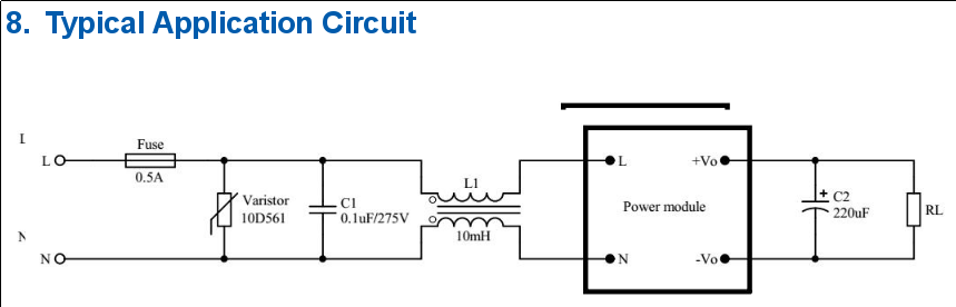
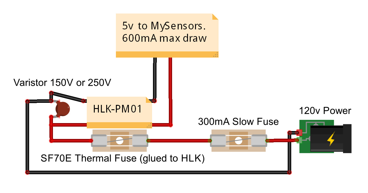
    The circuit behind that is really simple to build: a 3.3V power adapter, two optotriacs, two diodes, a microcontroller, a few resistors and a radio basically.

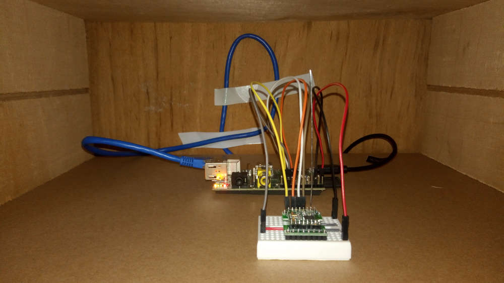
    On the gateway side, HomeAssistant is running on a Raspberry Pi 1 and I attached to that board an RFM69W radio in the "serial gateway" configuration.
    It has been built with the right configuration options: encryption enabled, rmf69w radio defined, etc.
    I also defined a random AES and HMAC key in the configuration file used by the gateway.

    On the "actuator" side if I can say so, I first tested the setup I'm trying to build with an Arduino Uno, another RFM69W, the right level converter between the radio and the Arduino Uno, and finally the controlling circuit.
    I followed the procedure to make signing work: run the SecurityPersonalizer sketch with the keys defined and then uploaded my pilot wire code.

    This first prototype using the Arduino Uno worked well: I could see nonces being exchanged in the debug view of the gateway, the commands sent / received and the state changing on the Arduino side (thanks to diodes). I am now planning to make a second more "realistic" prototype.
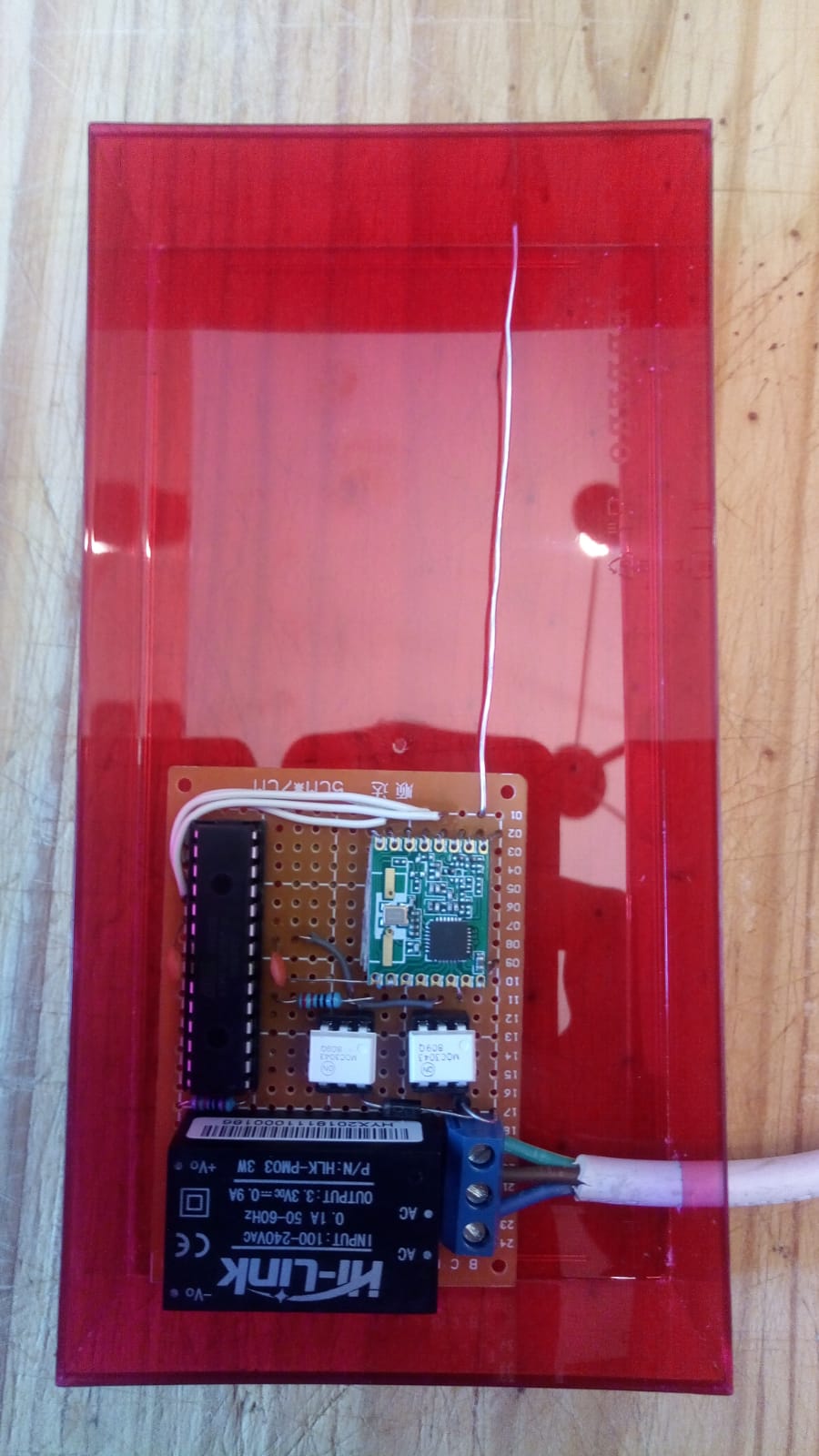
    My goal is to produce PCBs with the minimum number of components ; I'll therefore replace the Arduino Uno by an ATMEGA328P with the internal 8MHz clock, two capacitors between (A)Vin and GND, and a resistor near the "not RESET" pin.

    An important note before talking about the issue: I bought the ATMEGAs directly from Microchip (RIP Atmel :P) and the RFM69W radios directly from HopeRF.
    So, these are genuine components! ;)

    Now, the issue:
    I uploaded the SecurityPersonalizer sketch to the ATMEGA328P, made sure it was executed correctly and then I pushed my "pilot wire" sketch.
    For an unknown reason, the node fails to register and I can't see any message on the gateway side.
    Here are the "actuator" logs:

     __  __       ____
    |  \/  |_   _/ ___|  ___ _ __  ___  ___  _ __ ___
    | |\/| | | | \___ \ / _ \ `_ \/ __|/ _ \| `__/ __|
    | |  | | |_| |___| |  __/ | | \__ \  _  | |  \__ \
    |_|  |_|\__, |____/ \___|_| |_|___/\___/|_|  |___/
            |___/                      2.3.1
    
    16 MCO:BGN:INIT NODE,CP=RPNNAS-X,REL=255,VER=2.3.1
    63 TSM:INIT
    63 TSF:WUR:MS=0
    67 TSM:INIT:TSP OK
    67 TSM:FPAR
    75 TSF:MSG:SEND,255-255-255-255,s=255,c=3,t=7,pt=0,l=0,sg=0,ft=0,st=OK:
    2390 TSF:MSG:READ,51-180-176,s=199,c=3,t=129,pt=3,l=23,sg=1:0
    2398 !TSF:MSG:LEN=7,EXP=32
    2400 !TSM:FPAR:NO REPLY
    2402 TSM:FPAR
    2410 TSF:MSG:SEND,255-255-255-255,s=255,c=3,t=7,pt=0,l=0,sg=0,ft=0,st=OK:
    4278 TSF:MSG:READ,51-180-176,s=199,c=3,t=129,pt=3,l=23,sg=1:0
    4286 !TSF:MSG:LEN=7,EXP=32
    4419 !TSM:FPAR:NO REPLY
    4421 TSM:FPAR
    4427 TSF:MSG:SEND,255-255-255-255,s=255,c=3,t=7,pt=0,l=0,sg=0,ft=0,st=OK:
    6436 !TSM:FPAR:NO REPLY
    6438 TSM:FPAR
    6445 TSF:MSG:SEND,255-255-255-255,s=255,c=3,t=7,pt=0,l=0,sg=0,ft=0,st=OK:
    8454 !TSM:FPAR:FAIL
    8456 TSM:FAIL:CNT=1
    8458 TSM:FAIL:DIS
    8460 TSF:TDI:TSL
    18462 TSM:FAIL:RE-INIT
    18464 TSM:INIT
    18466 TSM:INIT:TSP OK
    18468 TSM:FPAR
    18477 TSF:MSG:SEND,255-255-255-255,s=255,c=3,t=7,pt=0,l=0,sg=0,ft=0,st=OK:
    20486 !TSM:FPAR:NO REPLY
    20488 TSM:FPAR
    20494 TSF:MSG:SEND,255-255-255-255,s=255,c=3,t=7,pt=0,l=0,sg=0,ft=0,st=OK:
    22503 !TSM:FPAR:NO REPLY
    22505 TSM:FPAR
    22511 TSF:MSG:SEND,255-255-255-255,s=255,c=3,t=7,pt=0,l=0,sg=0,ft=0,st=OK:
    24520 !TSM:FPAR:NO REPLY
    24522 TSM:FPAR
    24528 TSF:MSG:SEND,255-255-255-255,s=255,c=3,t=7,pt=0,l=0,sg=0,ft=0,st=OK:
    26540 !TSM:FPAR:FAIL
    26542 TSM:FAIL:CNT=2
    26544 TSM:FAIL:DIS
    26546 TSF:TDI:TSL
    36550 TSM:FAIL:RE-INIT
    (etc)
    

    When this problem appeared, I followed the pieces of advice given on this forum: I ran the "clear EEPROM" sketch, re-run the SecurityPersonalizer sketch and re-pushed my pilot wire sketch. Still no luck :(

    I started to believe the problem could be at the hardware level.
    I disabled encryption on the gateway (after rebuilding it) and in my sketch... and the actuator managed to register:

     __  __       ____
    |  \/  |_   _/ ___|  ___ _ __  ___  ___  _ __ ___
    | |\/| | | | \___ \ / _ \ `_ \/ __|/ _ \| `__/ __|
    | |  | | |_| |___| |  __/ | | \__ \  _  | |  \__ \
    |_|  |_|\__, |____/ \___|_| |_|___/\___/|_|  |___/
            |___/                      2.3.1
    
    16 MCO:BGN:INIT NODE,CP=RPNNA---,REL=255,VER=2.3.1
    28 TSM:INIT
    28 TSF:WUR:MS=0
    30 TSM:INIT:TSP OK
    32 TSM:FPAR
    38 TSF:MSG:SEND,255-255-255-255,s=255,c=3,t=7,pt=0,l=0,sg=0,ft=0,st=OK:
    440 TSF:MSG:READ,0-0-255,s=255,c=3,t=8,pt=1,l=1,sg=0:0
    446 TSF:MSG:FPAR OK,ID=0,D=1
    2048 TSM:FPAR:OK
    2048 TSM:ID
    2050 TSM:ID:REQ
    2066 TSF:MSG:SEND,255-255-0-0,s=2,c=3,t=3,pt=0,l=0,sg=0,ft=0,st=OK:
    2574 TSF:MSG:READ,0-0-255,s=2,c=3,t=4,pt=0,l=1,sg=0:1
    2580 TSF:SID:OK,ID=1
    2584 TSM:ID:OK
    2584 TSM:UPL
    2600 TSF:MSG:SEND,1-1-0-0,s=255,c=3,t=24,pt=1,l=1,sg=0,ft=0,st=OK:1
    2820 TSF:MSG:READ,0-0-1,s=255,c=3,t=25,pt=1,l=1,sg=0:1
    2824 TSF:MSG:PONG RECV,HP=1
    2828 TSM:UPL:OK
    2830 TSM:READY:ID=1,PAR=0,DIS=1
    2844 TSF:MSG:SEND,1-1-0-0,s=255,c=3,t=15,pt=6,l=2,sg=0,ft=0,st=OK:0100
    3055 TSF:MSG:READ,0-0-1,s=255,c=3,t=15,pt=6,l=2,sg=0:0100
    3080 TSF:MSG:SEND,1-1-0-0,s=255,c=0,t=17,pt=0,l=5,sg=0,ft=0,st=OK:2.3.1
    3602 TSF:MSG:SEND,1-1-0-0,s=255,c=3,t=6,pt=1,l=1,sg=0,ft=0,st=OK:0
    3649 TSF:MSG:READ,0-0-1,s=255,c=3,t=6,pt=0,l=1,sg=0:M
    3674 TSF:MSG:SEND,1-1-0-0,s=255,c=3,t=11,pt=0,l=10,sg=0,ft=0,st=OK:Fil pilote
    4196 TSF:MSG:SEND,1-1-0-0,s=255,c=3,t=12,pt=0,l=3,sg=0,ft=0,st=OK:1.0
    4229 TSF:MSG:SEND,1-1-0-0,s=0,c=0,t=4,pt=0,l=0,sg=0,ft=0,st=OK:
    4237 MCO:REG:REQ
    4751 TSF:MSG:SEND,1-1-0-0,s=255,c=3,t=26,pt=1,l=1,sg=0,ft=0,st=OK:2
    4968 TSF:MSG:READ,0-0-1,s=255,c=3,t=27,pt=1,l=1,sg=0:1
    4974 MCO:PIM:NODE REG=1
    4978 MCO:BGN:STP
    4978 MCO:BGN:INIT OK,TSP=1
    4995 TSF:MSG:SEND,1-1-0-0,s=0,c=1,t=2,pt=2,l=2,sg=0,ft=0,st=OK:1
    5521 TSF:MSG:SEND,1-1-0-0,s=0,c=1,t=3,pt=2,l=2,sg=0,ft=0,st=OK:2
    589813 TSF:MSG:READ,0-0-1,s=0,c=1,t=3,pt=0,l=1,sg=0:6
    599988 TSF:MSG:READ,0-0-1,s=0,c=1,t=3,pt=0,l=1,sg=0:1
    611840 TSF:MSG:READ,0-0-1,s=0,c=1,t=3,pt=0,l=1,sg=0:3
    

    I could of course see messages being received / send on the gateway side too.

    To sum up
    Communication is successfully working between an Arduino Uno and the Serial Gateway with encryption + signing enabled but fails to work on a barebone ATMEGA328P.

    Here are a few questions / ideas I have regarding the issue:

    • Could the problem be the bootloader I used to flash the ATMEGA328P? I used the " breadboard-1-6-x.zip" found on the official Arduino website: https://www.arduino.cc/en/Tutorial/ArduinoToBreadboard. Maybe the fuses / EEPROM address it set / uses conflicts with what the SecurityPersonalizer sketch does?
    • It seems the encrypted packet is just ignored with encryption enabled since I can't see any logs on the gateway side. I was wondering: are the messages dropped at the radio level or at the software level?

    Thanks in advance for your help!

    Appendix -- Pilot wire code

    #define MY_DEBUG
    
    // MySensors configuration
    #define MY_RADIO_RFM69
    #define MY_RFM69_NEW_DRIVER
    #define MY_SIGNING_SOFT
    #define MY_SIGNING_SOFT_RANDOMSEED_PIN 7
    #define MY_SIGNING_REQUEST_SIGNATURES
    #define MY_RFM69_ENABLE_ENCRYPTION 
    
    // Include the libraries
    #include <MySensors.h>
    
    // Global settings
    #define CHILD_ID 0
    #define INITIAL_MODE 2
    #define MOC_P 3
    #define MOC_N 4
    
    // Global variables
    bool first_msg_sent = false;
    MyMessage status_msg(CHILD_ID, V_STATUS);
    MyMessage mode_msg(CHILD_ID, V_PERCENTAGE);
    
    void set_mode(int16_t mode) {
    	digitalWrite(MOC_N, mode & 1);
    	digitalWrite(MOC_P, mode & 2);
    }
    
    void presentation() { 
    	sendSketchInfo("Fil pilote", "1.0");
    	present(CHILD_ID, S_DIMMER);
    }
    
    void setup() {
    
    	// Make the MOC pins outputs
    	pinMode(MOC_P, OUTPUT);
    	pinMode(MOC_N, OUTPUT);
    
    	// Set the initial mode (2 = OFF)
    	set_mode(INITIAL_MODE);
    }
    
    void loop() {
    	if (!first_msg_sent) {
    		send(status_msg.set((int16_t) 1));
    		send(mode_msg.set((int16_t) INITIAL_MODE));
    		first_msg_sent = true;
    	}
    }
    
    void receive(const MyMessage &message) {
    	if(message.type == V_PERCENTAGE) {
    		set_mode(message.getInt());
    	}
    }
    
    Troubleshooting atmega328p rfm69w security

  • HLK-PMxx protection: choosing the right MOV / fuse value
    EncryptE Encrypt

    Hello!

    I am still working on a MySensors project which uses an HLK-PM03 module to provide 3.3V DC from mains to my circuit. This project was almost finished when I came across posts on forums recommending adding a fuse / varistor in front of the HLK-PM03 module to protect it.

    So I dug that subject a bit more and I came across a recent HLK-PMxx datasheet in which this is mentioned: https://datasheet.lcsc.com/szlcsc/1912111437_HI-LINK-HLK-PM12_C209905.pdf

    capture.png

    The fuse and varistor are really needed to protect the circuit ; the capacitor / inductance are apparently optional. In the datasheet, the constructor recommends using a 0.5A slow blow fuse and a 350V varistor (10D561K).

    But I found a discussion on the MySensors forums with completely different recommendations. This one typically: https://forum.mysensors.org/topic/1607/safe-in-wall-ac-to-dc-transformers
    The first post shows a diagram with a 0.3A slow blow fuse and a 250V varistor.

    alt text

    The choice of the "right" components really puzzled me recently, so here is my question: which varistor / fuse value should I select, at the end?

    I'm particularly interested in knowing how varistors (MOVs) should be chosen, because I have read so many conflicting arguments on different forums...

    A post of @skywatch I recently found (https://forum.mysensors.org/topic/9790/has-anyone-else-seen-a-varistor-mov-failure-in-a-power-supply?_=1597873012895) seems to confirm the choice of the manufacturer regarding the 350V RMS MOV.

    Finally, note that I live in France ; mains voltage here is 230V AC +/- 10%.

    Thanks in advance for your answers!
    Encrypt

    Hardware

  • Failed to make encryption work on a barebone ATMEGA328P
    EncryptE Encrypt

    @Anticimex: I have just found that there is an EESAVE fuse on the ATMEGA328P which prevents the EEPROM from being erased whenever a new sketch is pushed to the microcontroller.

    It seems to be the root cause of the issue since I've found references in other posts of the MySensors forum to that problem.

    I'll test that now and let you know.

    Troubleshooting atmega328p rfm69w security

  • HLK-PMxx protection: choosing the right MOV / fuse value
    EncryptE Encrypt

    Hello @skywatch !

    Thank you very much for your answer! It is now clear for me! :)

    Cheers!

    Hardware

  • Failed to make encryption work on a barebone ATMEGA328P
    EncryptE Encrypt

    IT WORKS @Anticimex !!! :the_horns:

    The issue was indeed the EESAVE fuse not set, which caused the EEPROM to be erased after each sketch upload.

    Here is my modified boards.txt file:

    ##############################################################
    
    atmega328bb.name=ATmega328 on a breadboard (8 MHz internal clock)
    
    atmega328bb.upload.protocol=arduino
    atmega328bb.upload.maximum_size=30720
    atmega328bb.upload.speed=57600
    
    atmega328bb.bootloader.low_fuses=0xE2
    atmega328bb.bootloader.high_fuses=0xD2
    atmega328bb.bootloader.extended_fuses=0x05
    
    atmega328bb.bootloader.file=atmega/ATmegaBOOT_168_atmega328_pro_8MHz.hex
    atmega328bb.bootloader.unlock_bits=0x3F
    atmega328bb.bootloader.lock_bits=0x0F
    
    atmega328bb.build.board=AVR_ATMEGA328BB
    atmega328bb.build.mcu=atmega328p
    atmega328bb.build.f_cpu=8000000L
    atmega328bb.build.core=arduino:arduino
    atmega328bb.build.variant=arduino:standard
    
    
    atmega328bb.bootloader.tool=arduino:avrdude
    atmega328bb.upload.tool=arduino:avrdude
    

    So, basically, for people coming here in the future:
    Follow the tutorial https://www.arduino.cc/en/Tutorial/ArduinoToBreadboard to flash the bootloader of your ATMEGA328P but replace the given boards.txt file (in the breadboard-1-6-x.zip archive) by the one above.

    A useful link to calculate the fuses values: http://www.engbedded.com/fusecalc/

    Thanks for your help @Anticimex, @mfalkvidd and @kimot :)

    Troubleshooting atmega328p rfm69w security

  • Signing fails due to NACKed messages
    EncryptE Encrypt

    Hello everyone!

    I am experiencing issues with my "pilot wire" node (controlling one of my heaters) since a few days.

    At 8:00 a.m., the MySensors gateway is supposed to send a V_PERCENTAGE message to the heater with "0" as payload, so that it goes into comfort mode and starts heating.
    At the opposite, at 10:00 p.m., a V_PERCENTAGE message with "3" as payload is sent to the heater so that it goes into "eco" mode.

    All communications are encrypted on my MySensors network and the pilot wire node requires signed messages. Everything was correctly set up (after long discussions here :stuck_out_tongue_winking_eye:) and it has been working well for months.

    However, I'm starting to get "!TSF:MSG:SIGN FAIL" messages on the MySensors gateway and the heater therefore fails to change of mode. Here are relevant logs:

    Nov 10 07:35:21 DEBUG TSM:READY:NWD REQ
    Nov 10 07:35:21 DEBUG TSF:MSG:SEND,0-0-255-255,s=255,c=3,t=20,pt=0,l=0,sg=0,ft=0,st=OK:
    Nov 10 07:35:21 DEBUG TSF:SAN:OK
    Nov 10 07:50:21 DEBUG TSF:SAN:OK
    Nov 10 07:55:21 DEBUG TSM:READY:NWD REQ
    Nov 10 07:55:21 DEBUG TSF:MSG:SEND,0-0-255-255,s=255,c=3,t=20,pt=0,l=0,sg=0,ft=0,st=OK:
    Nov 10 08:00:01 DEBUG !TSF:MSG:SEND,0-0-2-2,s=0,c=3,t=16,pt=0,l=0,sg=1,ft=0,st=NACK:
    Nov 10 08:00:01 DEBUG !TSF:MSG:SIGN FAIL
    Nov 10 08:05:21 DEBUG TSF:SRT:OK
    Nov 10 08:05:21 DEBUG TSF:SAN:OK
    Nov 10 08:15:21 DEBUG TSM:READY:NWD REQ
    Nov 10 08:15:21 DEBUG TSF:MSG:SEND,0-0-255-255,s=255,c=3,t=20,pt=0,l=0,sg=0,ft=0,st=OK:
    Nov 10 08:20:21 DEBUG TSF:SAN:OK
    Nov 10 08:35:21 DEBUG TSF:SRT:OK
    Nov 10 08:35:21 DEBUG TSM:READY:NWD REQ
    Nov 10 08:35:21 DEBUG TSF:MSG:SEND,0-0-255-255,s=255,c=3,t=20,pt=0,l=0,sg=0,ft=0,st=OK:
    Nov 10 08:35:21 DEBUG TSF:SAN:OK
    Nov 10 08:50:21 DEBUG TSF:SAN:OK
    Nov 10 08:55:21 DEBUG TSM:READY:NWD REQ
    Nov 10 08:55:21 DEBUG TSF:MSG:SEND,0-0-255-255,s=255,c=3,t=20,pt=0,l=0,sg=0,ft=0,st=OK:
    Nov 10 09:05:21 DEBUG TSF:SRT:OK
    Nov 10 09:05:21 DEBUG TSF:SAN:OK
    Nov 10 09:15:21 DEBUG TSM:READY:NWD REQ
    Nov 10 09:15:21 DEBUG TSF:MSG:SEND,0-0-255-255,s=255,c=3,t=20,pt=0,l=0,sg=0,ft=0,st=OK:
    Nov 10 09:20:21 DEBUG TSF:SAN:OK
    Nov 10 09:35:21 DEBUG TSF:SRT:OK
    Nov 10 09:35:21 DEBUG TSM:READY:NWD REQ
    Nov 10 09:35:21 DEBUG TSF:MSG:SEND,0-0-255-255,s=255,c=3,t=20,pt=0,l=0,sg=0,ft=0,st=OK:
    Nov 10 09:35:21 DEBUG TSF:SAN:OK
    Nov 10 09:50:21 DEBUG TSF:SAN:OK
    Nov 10 09:55:21 DEBUG TSM:READY:NWD REQ
    Nov 10 09:55:21 DEBUG TSF:MSG:SEND,0-0-255-255,s=255,c=3,t=20,pt=0,l=0,sg=0,ft=0,st=OK:
    Nov 10 10:05:21 DEBUG TSF:SRT:OK
    Nov 10 10:05:21 DEBUG TSF:SAN:OK
    Nov 10 10:10:30 DEBUG !TSF:MSG:SEND,0-0-2-2,s=0,c=3,t=16,pt=0,l=0,sg=1,ft=0,st=NACK:
    Nov 10 10:10:30 DEBUG !TSF:MSG:SIGN FAIL
    Nov 10 10:10:30 DEBUG TSF:MSG:READ,2-2-0,s=255,c=3,t=17,pt=6,l=25,sg=1:<NONCE>
    Nov 10 10:10:34 DEBUG TSF:MSG:SEND,0-0-2-2,s=0,c=3,t=16,pt=0,l=0,sg=1,ft=0,st=OK:
    Nov 10 10:10:34 DEBUG TSF:MSG:READ,2-2-0,s=255,c=3,t=17,pt=6,l=25,sg=1:<NONCE>
    Nov 10 10:10:34 DEBUG TSF:MSG:SEND,0-0-2-2,s=0,c=1,t=3,pt=0,l=1,sg=1,ft=0,st=OK:0
    

    As you can see, when I noticed that the heater was cold at 10:10 a.m. this morning, I changed the mode back to something else ("Off", which failed) and changed again to comfort (and this time, it worked).

    Do you have any clue why this is happening? Note that I haven't touched to the hardware.
    Is there a way to tell MySensors to re-send a message if it fails? Or maybe I could do something on the HomeAssistant side?

    Also, note that the radios used are RFM69W modules. Regarding location, the node is at the basement, the gateway is upstairs and if you drew a line through the walls, the distance between both is approximately 15 meters, I'd say.

    Thanks in advance for your help!

    #-------------------- Appendix --------------------#

    My Raspberry Pi serial Gateway:
    0_1573387957073_P_20191110_130510.jpg

    My pilot wire prototype:
    0_1573388005746_pilot_wire.jpg

    Troubleshooting

  • A water pulse meter using interrupts and the ATMEGA328P "power save" mode
    EncryptE Encrypt

    Thanks for the feedback @zboblamont!
    I was probably overthinking the whole thing :P

    Troubleshooting

  • Unable to read data from my (Linky) electricity meter
    EncryptE Encrypt

    Hello everyone!

    Thank you @mfalkvidd for your answer.
    I finally found the issue...

    Timing is particularly critical when reading UART and using the internal RC oscillator isn't a good idea... at all. Especially knowing that its frequency varies (quite a lot in my opinion) with temperature:

    capture.png
    (Page 274 of the ATMEGA328P datasheet available here: https://ww1.microchip.com/downloads/en/DeviceDoc/Atmel-7810-Automotive-Microcontrollers-ATmega328P_Datasheet.pdf)

    So, I changed the fuses of the ATMEGA328P to use an external 8 MHz crystal oscillator and now everything works perfectly! :champagne:

    Regarding the code, I've initialized the "Serial" object with the configuration SERIAL_7E1, it works as expected!

    Cheers!
    Encrypt

    Troubleshooting
  • Login

  • Don't have an account? Register

  • Login or register to search.
  • First post
    Last post
0
  • MySensors
  • OpenHardware.io
  • Categories
  • Recent
  • Tags
  • Popular