If you use Set to send your temp/hum you can define how many decimals you want:
MyMessage& set(float value, uint8_t decimals);
For example:
gw.send(msgTemp.set(temperature, 1));
will send you the value with 1 decimal.
Reference: here
If you use Set to send your temp/hum you can define how many decimals you want:
MyMessage& set(float value, uint8_t decimals);
For example:
gw.send(msgTemp.set(temperature, 1));
will send you the value with 1 decimal.
Reference: here
I have it working :smiley: only need to play with the debounce value
@ahmedadelhosni that really sucks :disappointed:
mfalkvidd means:
gw.wait(dht.getMinimumSamplingPeriod());
In the first sketch change
gw.begin (msg, NODE_ID) ;
to
gw.begin (NULL, NODE_ID) ;
Another way is to track the amount of people that enters the room. This can be done with a double IR beam horizontally placed next to each-other (IR-A and IR-B). Now when a person walks into the room, you know that IR-A triggers before IR-B, and you increment the room-occupants-counter with 1. If the person leaves the room, IR-B will trigger before IR-A and you decrease the counter.
The IR barrier can be installed inside the door casing.
Using this technique you don't need a PIR sensor, unless the room has a window and you want to detect movement without someone passed the IR beams (a burglar maybe?)
Combine the IR beams with a lightsensor and you can also define that the light should go on only below a certain light level.
My 2 cents...
Maybe this will help: http://jmsarduino.blogspot.be/2009/10/4-way-button-click-double-click-hold.html
Is your controller setup to hand out ID's to the sensor nodes?
What if you set a fixed ID?
I'm developing a controller and I reset my sensor nodes all the time and the ethernet gateway keeps working as expected.
My advice: do not power your nRF from the arduino 3.3V pin, instead, take power from the 5V pin and step that down to 3.3V using a voltage regulator. (like LM1777 including caps)
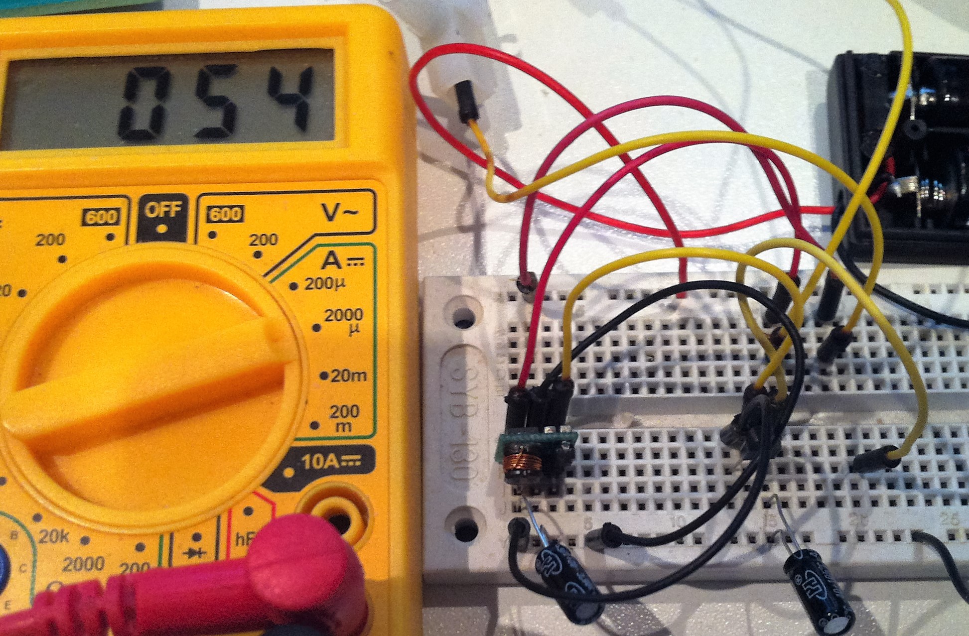
Just took the time to shoot a pic of my Step-Up consumption, including a Voltage regulator MCP1702-3.3
As you can see, it's consuming 54uA with nothing connected.
Step-Up module: link
The capacitors are really important, one on the input of the step-up module, the other on the output of the MCP1702-3.3, both are 22uF. Without them, consumption is 2.20mA
please indent your code with 4 spaces to keep it readable.
And in the arduino gui press CTRL-T to tabify your code correctly ;)
The high-performance Atmel® ATmega328PB is an 8-bit AVR RISC-based microcontroller (MCU) with picoPower® technology. It combines 32kB ISP Flash memory with read-while-write capabilities, 1kB EEPROM, 2kB SRAM, 27 general purpose I/O lines, 32 general purpose working registers, five flexible timer/counters with compare modes, internal and external interrupts, two USARTs with wake-up on start of transmission, two byte-oriented 2-wire serial interfaces, two SPI serial ports, 8-channel 10-bit A/D converter, programmable watchdog timer with internal oscillator, a unique serial number and six software selectable power saving modes. The device operates between 1.8-5.5 volts.
The ATmega328PB is the first 8-bit AVR MCU to feature the QTouch® Peripheral Touch Controller (PTC), which acquires signals in order to detect touch on capacitive sensors, and supports both self- and mutual-capacitance sensors. The PTC is supported by the QTouch Composer development tool (QTouch Library project builder and QTouch Analyzer). It provides a faster and less complex capacitive touch implementation in any application.
The ATmega328PB supports 24 buttons in self-capacitance mode, or up to 144 buttons in mutual-capacitance mode. Mixing and matching mutual-and self-capacitance sensors is possible, and only one pin is required per electrode – no external components are required, delivering savings on the BOM cost compared to competing solutions.
By executing powerful instructions in a single clock cycle, the device achieves throughputs approaching 1 MIPS per MHz, balancing power consumption and processing speed.
Nice feature for MySensors is that it has 2 SPI interfaces, so nice for the ethernet gateway ;) and also has a Unique ID
Application note here
Thanks to @samuel235 for finding this.
 Flash (Kbytes):				32 Kbytes
 Pin Count:						32
 Max. Operating Freq. (MHz):		20 MHz
 CPU:							8-bit AVR
 # of Touch Channels:			12
 Hardware QTouch Acquisition:	Yes
 Max I/O Pins:					27
 Ext Interrupts:				27
 USB Speed:						No
 USB Interface:					No
 SPI:							2
 TWI (I2C):						2
 UART:							2
 Graphic LCD:					No
 Video Decoder:					No
 Camera Interface:				No
 ADC Channels:					8
 ADC Resolution (bits):			10
 ADC Speed (ksps):				15
 Analog Comparators:			1
 Resistive Touch Screen:		No
 DAC Channels:					0
 DAC Resolution (bits):			0
 Temp. Sensor:					Yes
 Crypto Engine:					No
 SRAM (Kbytes):					2
 EEPROM (Bytes):				1024
 Self Program Memory:			YES
 External Bus Interface:		0
 DRAM Memory:					No
 NAND Interface:				No
 picoPower:						Yes
 Temp. Range (deg C):			-40 to 85
 I/O Supply Class:				1.8 to 5.5
 Operating Voltage (Vcc):		1.8 to 5.5
 FPU:							No
 MPU / MMU:						no / no
 Timers:						5
 Output Compare Channels:		10
 Input Capture Channels:		3
 PWM Channels:					10
 32kHz RTC:						Yes
 Calibrated RC Oscillator:		Yes
 Watchdog:						Yes
 CAN:							0
 LIN:							0
 Ethernet:						0
 Debug Interface:				debugWIRE
 I2S:							No
 RTC:							Counter
There are only 2 interrupts available, thats why you are not seeing the pulses from the 3th