the display node for my camper, based on a Arduino Mega clone
F
fsgraz
@fsgraz
Posts
-
What did you build today (Pictures) ? -
A few sensors for my camper (pandemic lockdown edition ...)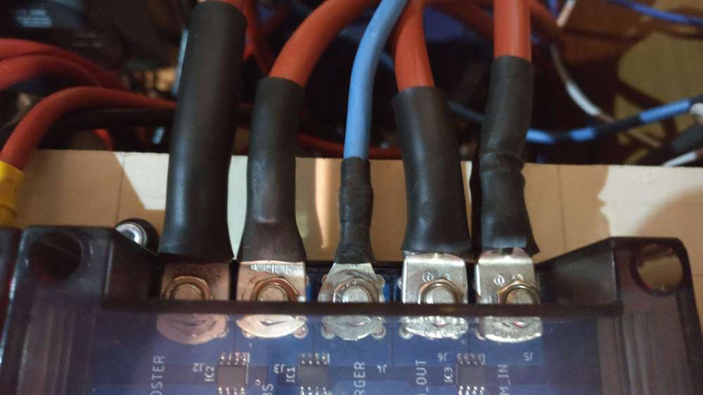


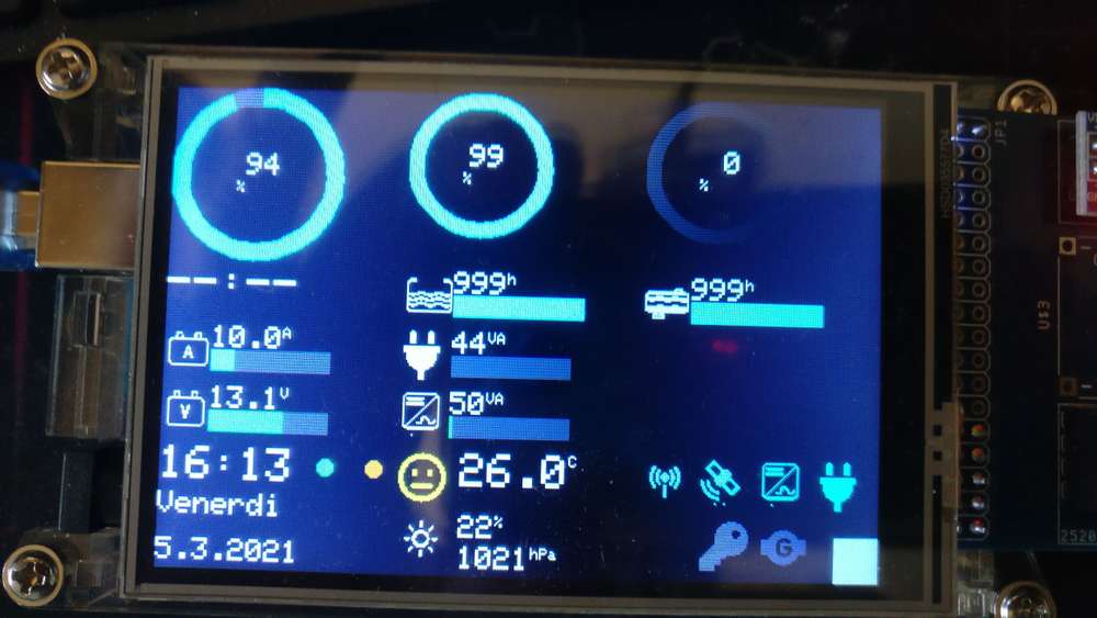
Charge Monitors
Batteries Monitor
Controller and Mobile Router
Fresh Water Level Monitor

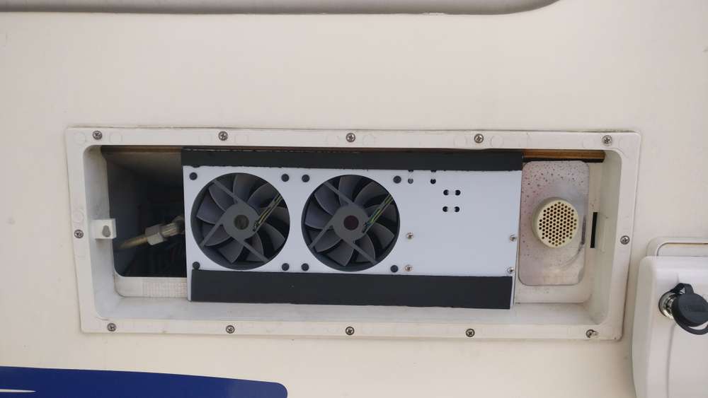
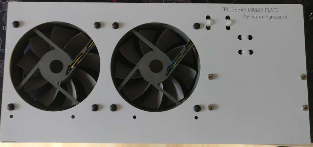
Fridge Fan Controller
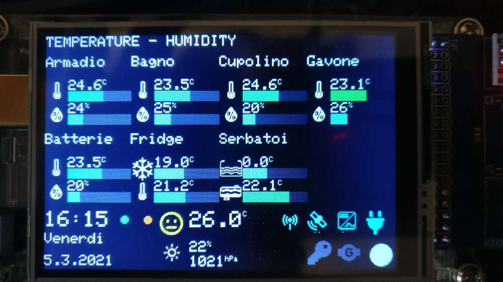
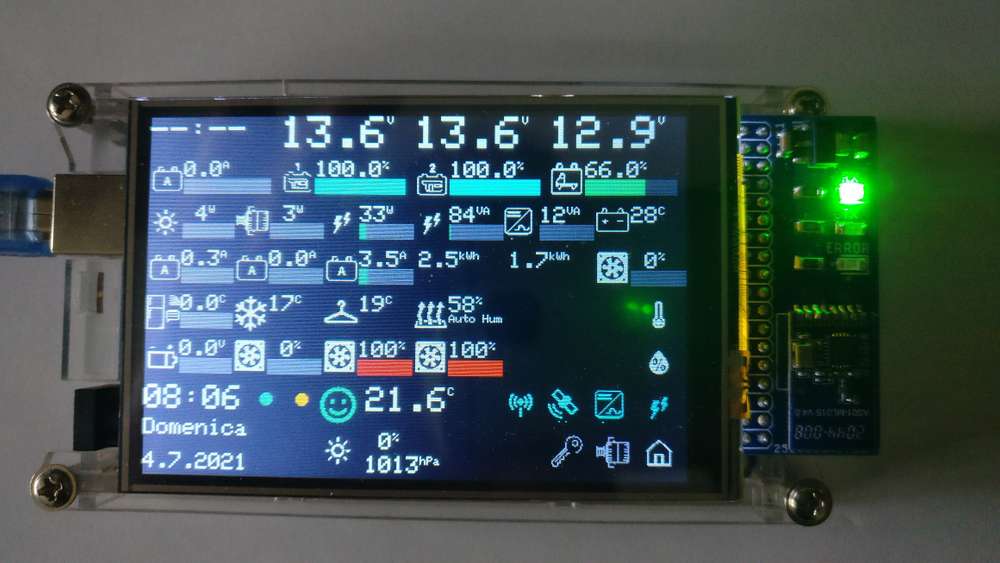
Display -
What did you build today (Pictures) ?A collection of the sensors and actuators I buit for my camper in the past year
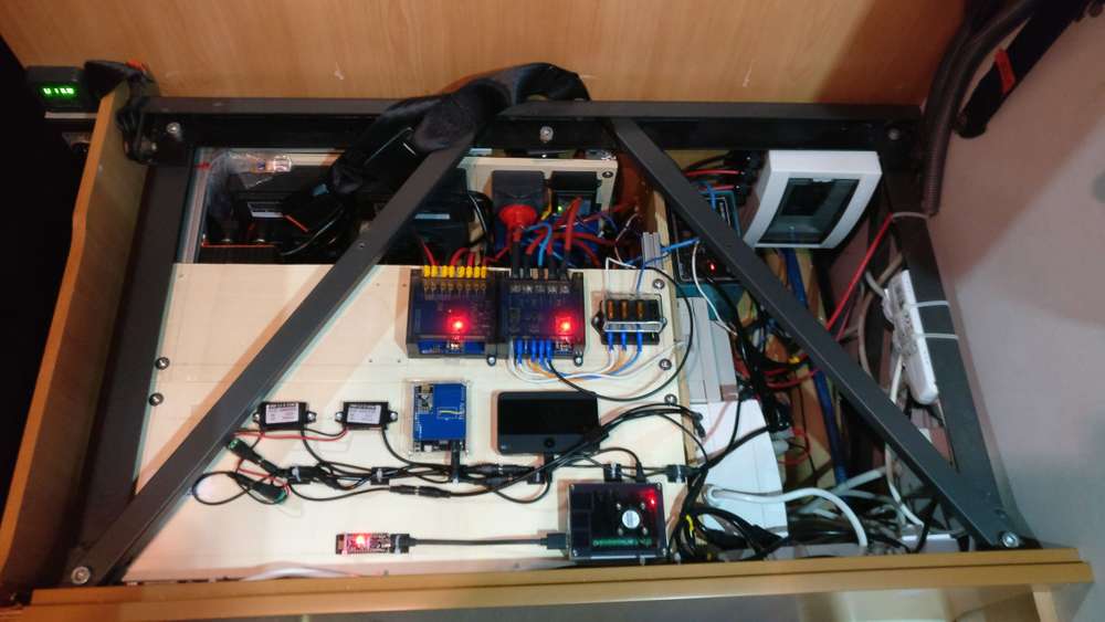
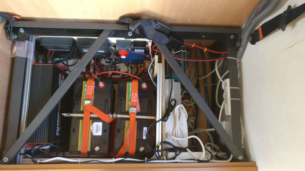
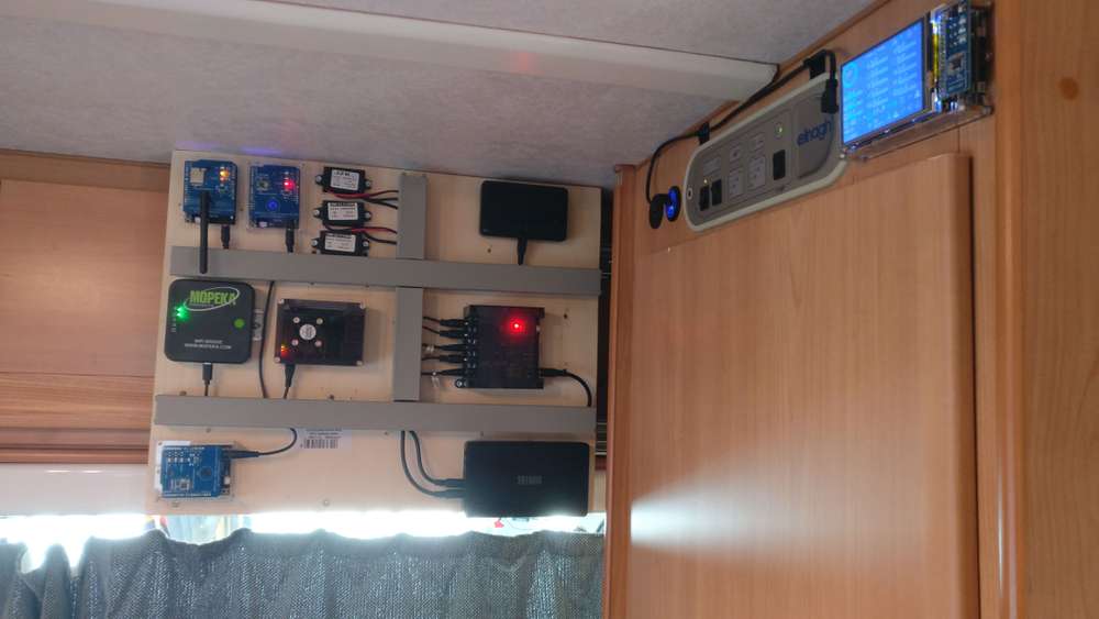
the power supply system under the dinette seat
the battery management system (purchased) data are read via wifi by an ESP32, which reports the info to the GW via nRF24L01+.a closed look at 2 sensors.
the one on the left reads voltage and current from the solar PV panel and to the battery management system
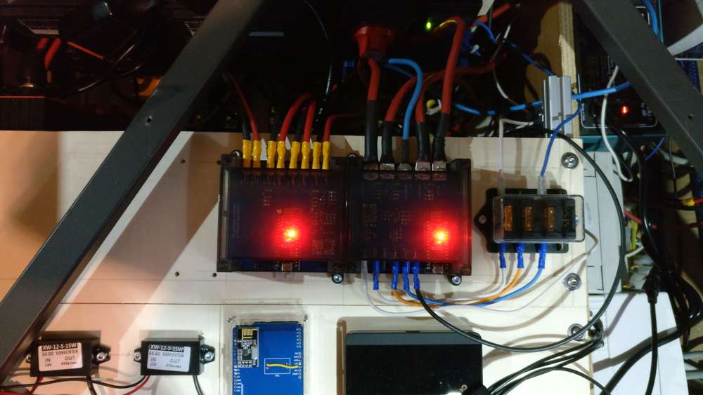
the one on the right reads voltage and current from/to the start and service batteriers
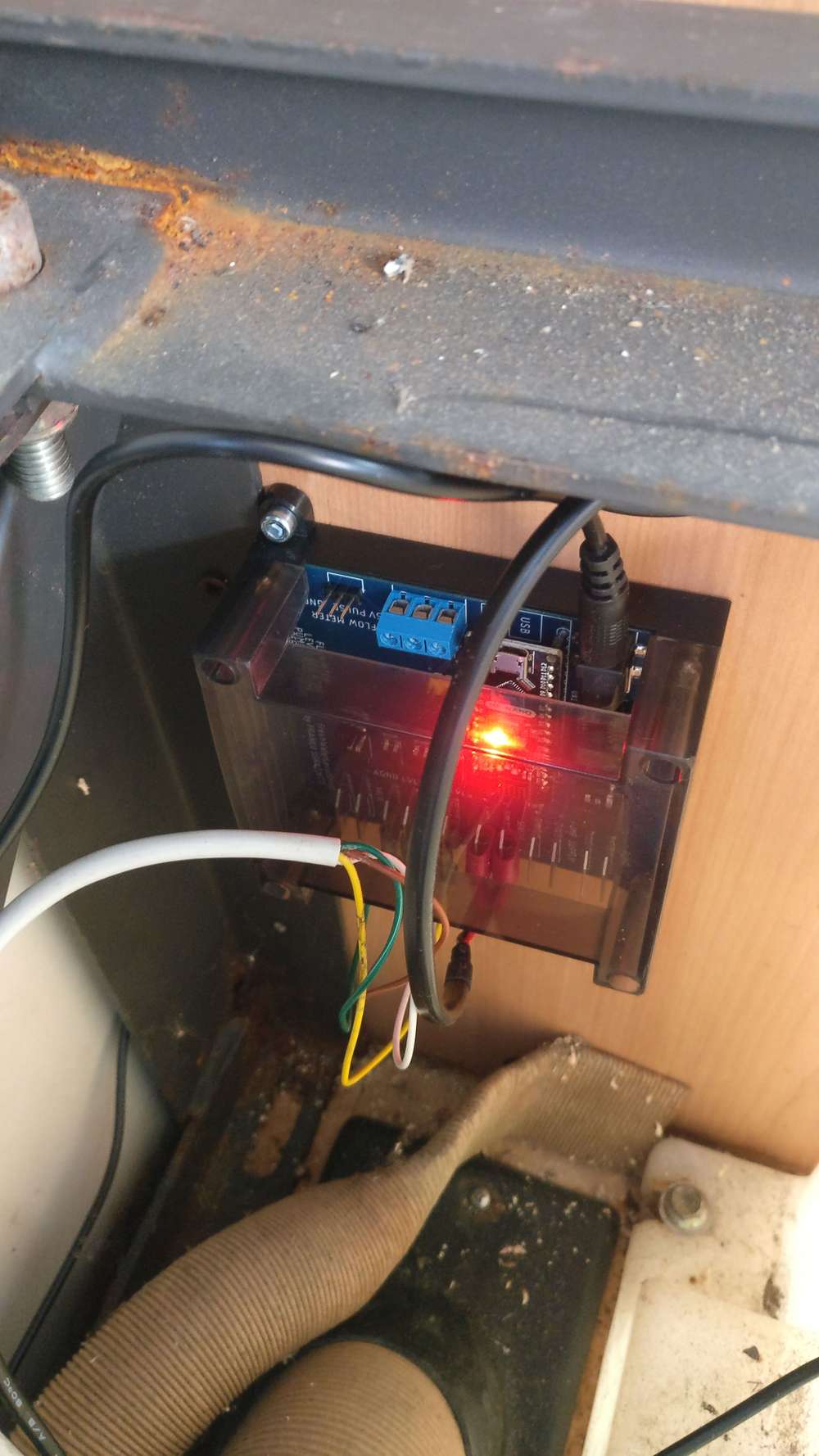
both sensors report instant power and energy.Fresh water sensor reads the water level, flow and temperature.
has 4 optcoupled outputs to send the information to the 4 LEDs of the original control panel of the camper

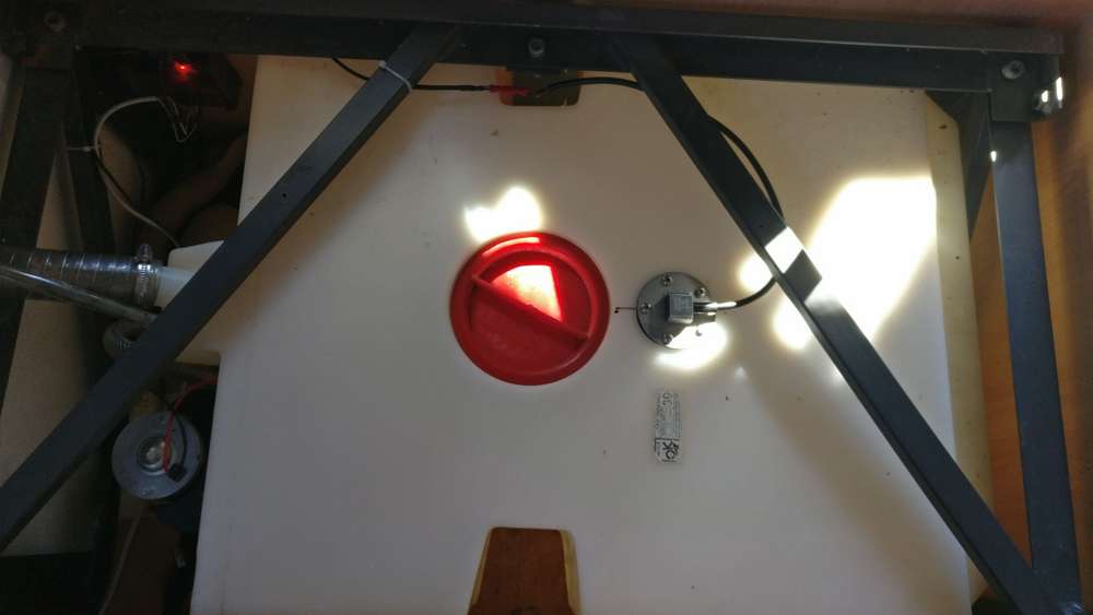
gray water tank sensor reports water level with an ultrasound sensor. has an optocoupled output to the "full" LED of the original control panel
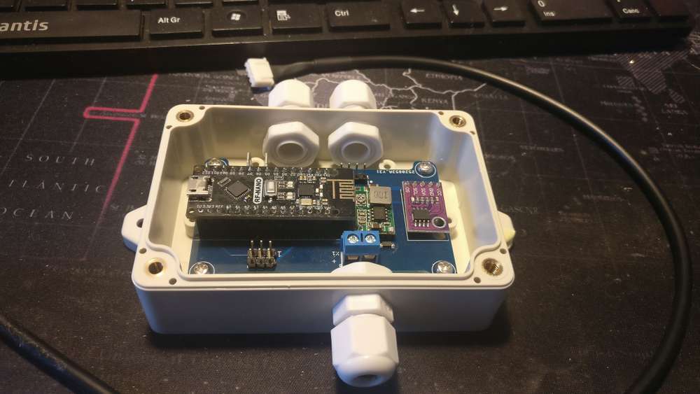
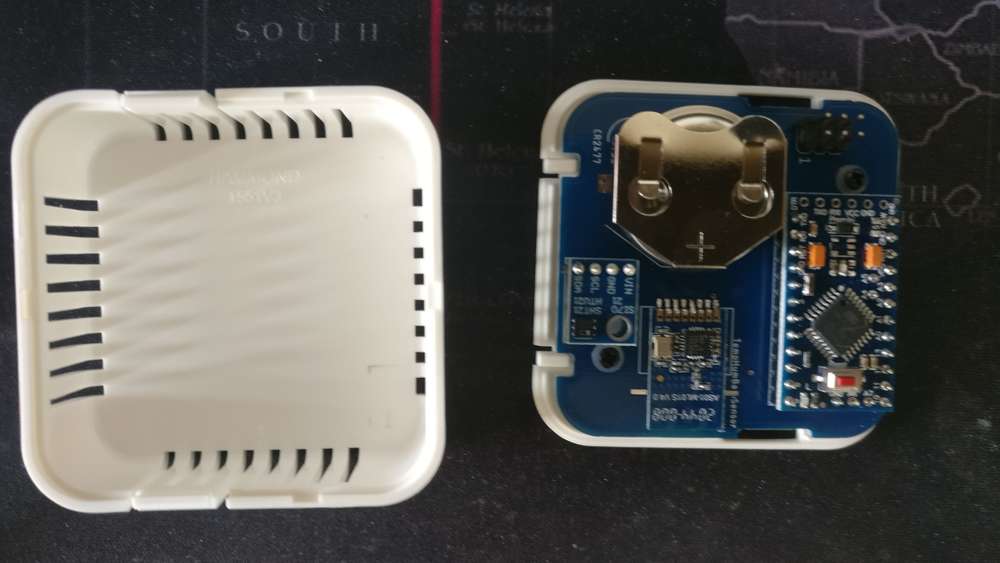
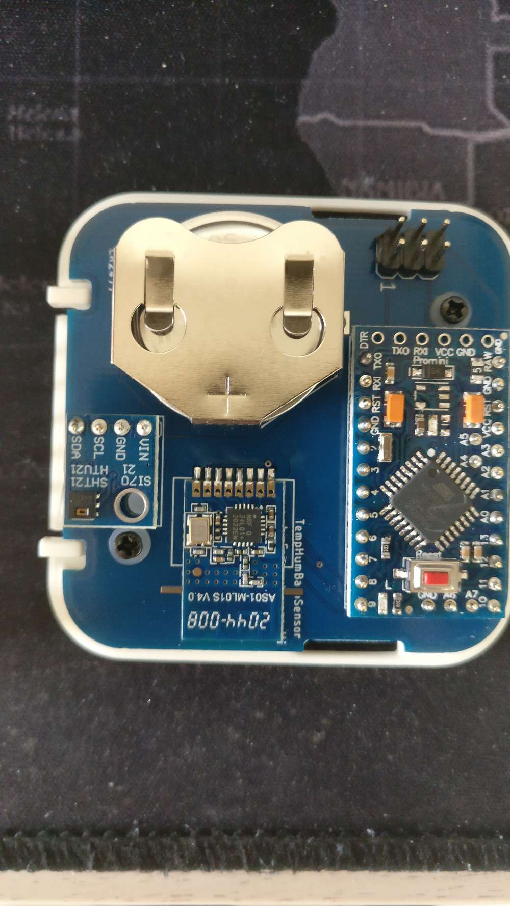
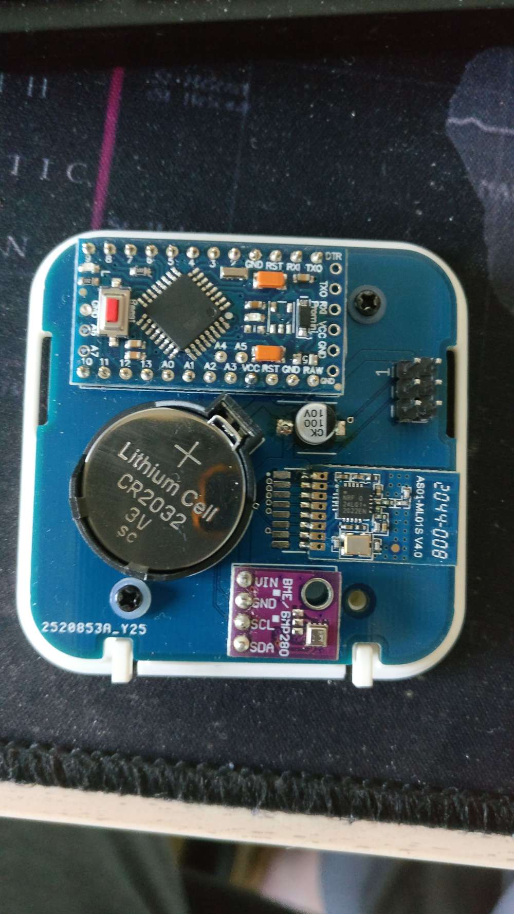
bettry supplied temperature and humidity sensor.
I use it in the fridge but also at home, where I have also one with BME280.
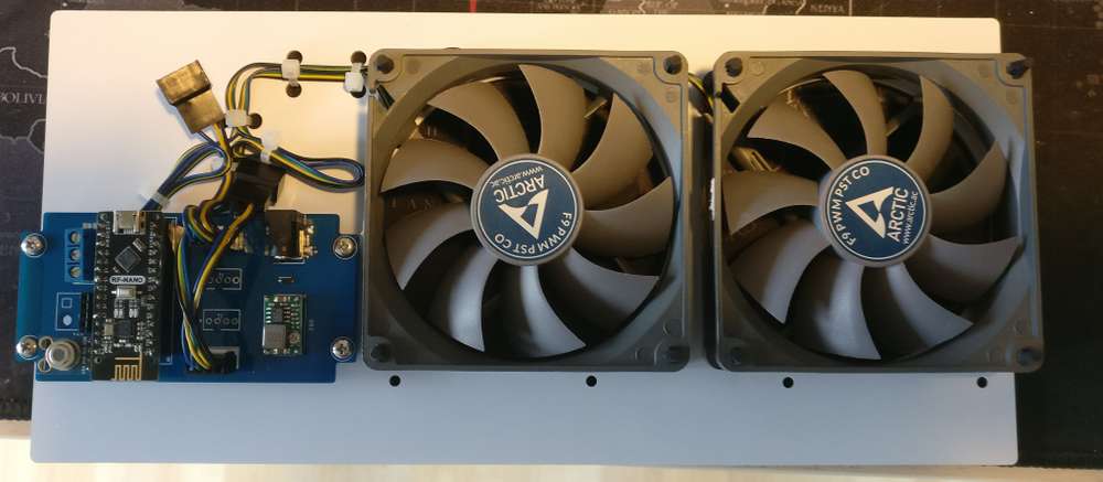
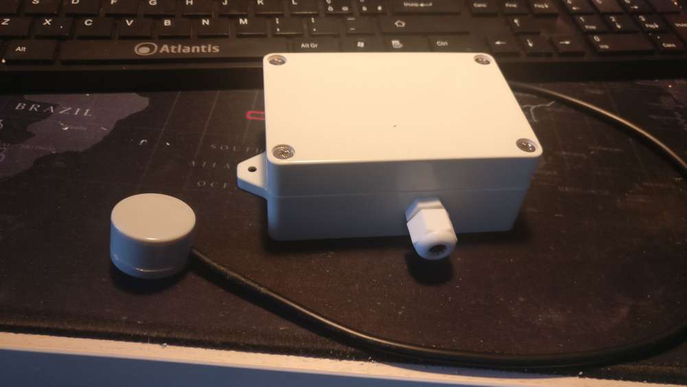
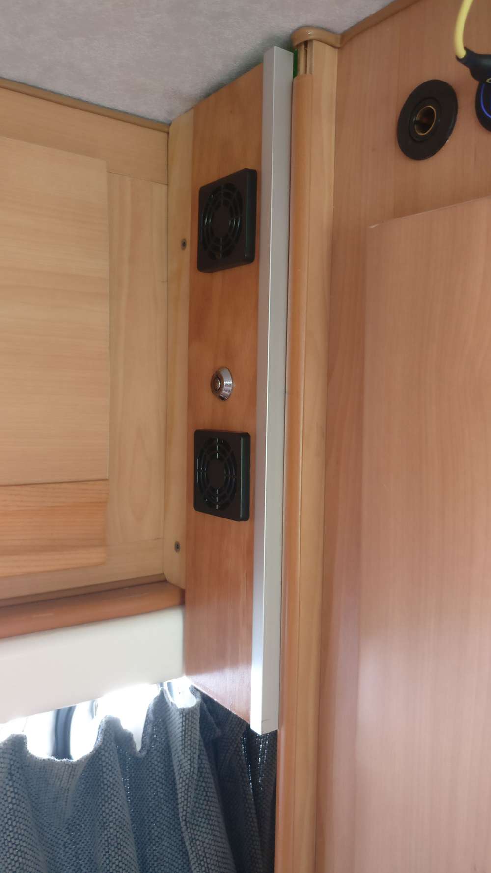
A fan controller to help the fridge to work better, controlling the condenser temperature using an optical thermometer sensor.
I have 3 other units, one in the power supply system, one in the closet and one on the roof.
They are all with a PID controller.

-
What did you build today (Pictures) ?Some updates in almost one year.
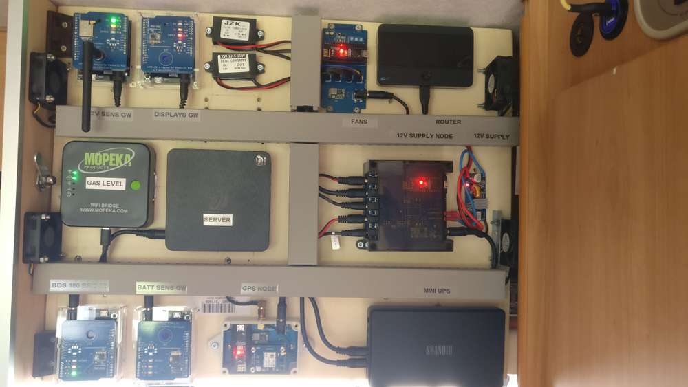
I moved all the gateways and controller part in a most suitable location
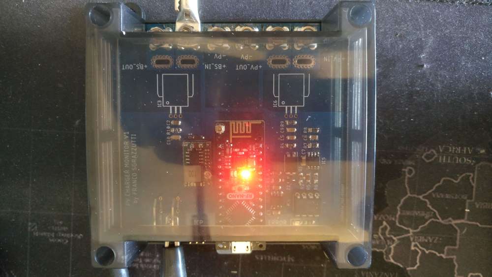
I've created a dual current sensor for the fuse box and the inverter. Each Current sensors can withstand 90A max, so I used both channels in parallel. The sensors are defined for both Channel 1, 2 and Sum(Ch1+Ch2) to handle this case easily
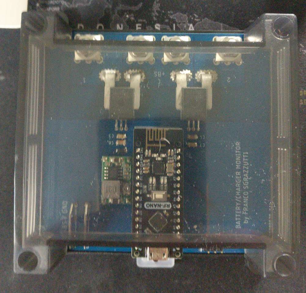
Recently I made an updated version of my Photovoltaic monitor since the 20A that the old one could withstand are not enough now, so the new version is capable of 50A max. Still waiting the Hall sensors though...
Finally, I cleaned up a bit the deployment under the bench
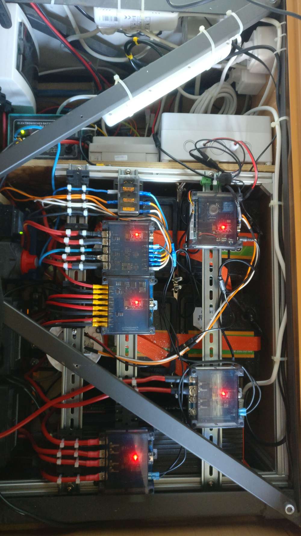 but I am not done yet
 -
What did you build today (Pictures) ?Finally I had the time to refine it:
-
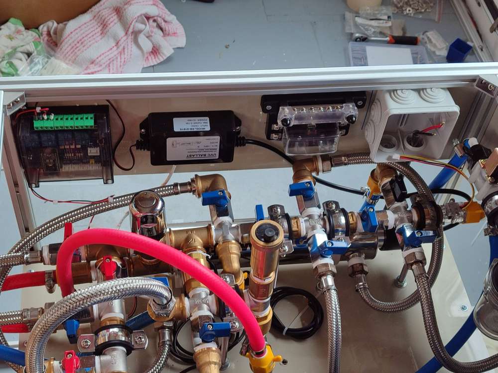
Water Filtering and Sterilization and Hot Water RecirculationMy RV is under restoration, so now or never. I wanted to experiment a bit out of the pure sensorics and iot and try another interesting use case:
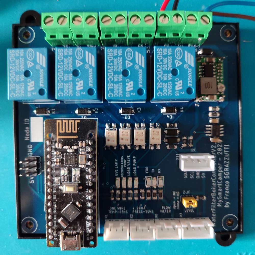
- 12V water boiler - in series with the Truma Combi gas boiler
- wireless node to handle the boiler power supply (see the link above)
- water tank loading with pre-filter, valve, pump and 1-stage filter
- water filter, ultra-violet sterilizer, thermostatic mixer and warm water recirculation.
This new node handles the water loading, starting the valve and the pump via a push button, and stopping after 10' or when a Tank Full capacitive sensor is enabled.
A water flow sensor switches on the UVC water sterilizer for a minimum of 15' (to save power and minimize the amount of power cycles applied to the UVC lamp).Three temperature sensors measure the temperature on the hot water delivery and return, and the connection between the Truma Combi boiler and the electric boiler.
The purpose is to keep the hot water always ready at the taps, keep the boilers water at the same temperature when needed and a few more other cases.A pressure sensor inhibits the recirculation pump and the UVC Lamp if the pressure is too low.
This time I've pushed myself out of the comfort zone.
-
Some questions on how gateway works@mfalkvidd I got what you mean.
Yes, I am using the tcp connection using the mySensors serial API, not the USB<>UART serial interface ;-)I am running a gateway with the nRF24 at 1Mpbs for the fast & furious sensors (mainly energy meters); another at 250kbps for the battery supplied nodes (temp/hum and door sensors); another one at 1Mbps dedicated to the actuators / mission critical.
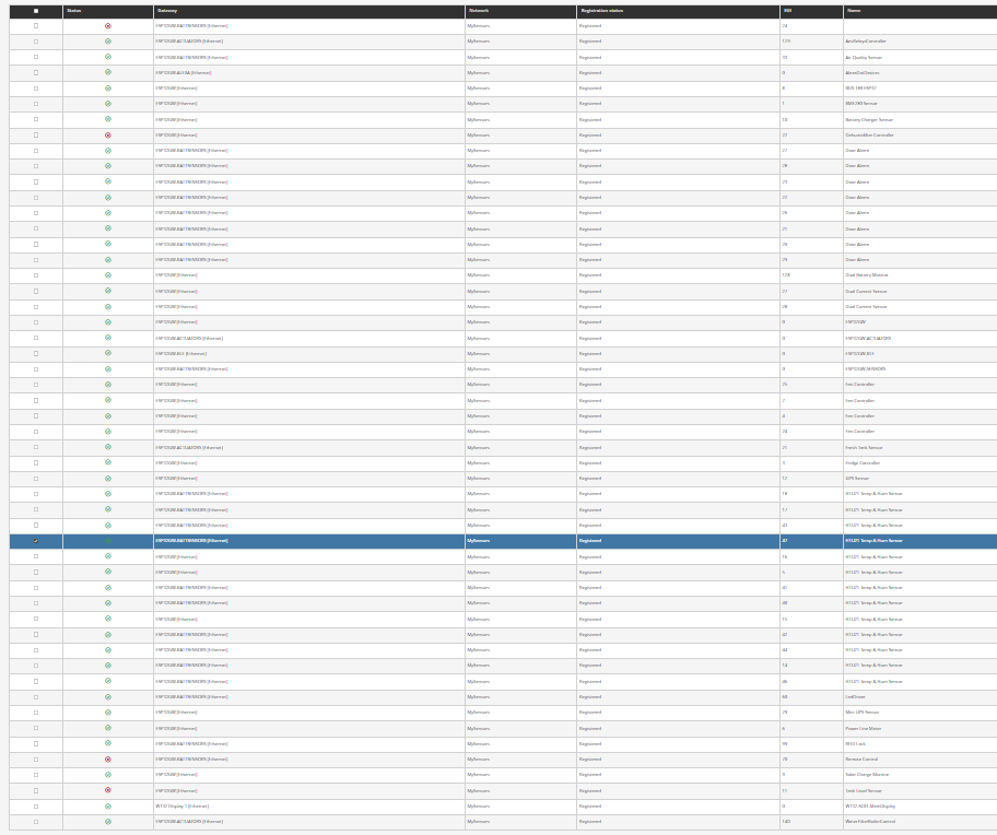
60 nodes runningAnother on is a BLE<>Mysensors bridge between the Mopeka Tank Pro (2) and the TPMS (4)
Another one is a fauxmo<>Mysensors bridge.A few esp32 based displays (round oled, 3.5", 7")
:-)
-
Keen to build againIt depends a lot on what you can do. As @OldSurferDude wrote, if you want a cheap solution, this is the way to go. Also when you need something that is not available on the market. Here below the list of my camper nodes.
IMO mySensors is the best possible alternative, if not the only one, to the systems that rely on standards, which require way too many resources for the job they are asked.
In my case, several nodes have edge capabilities, because they have to keep working even if the controller is not responsive.
-
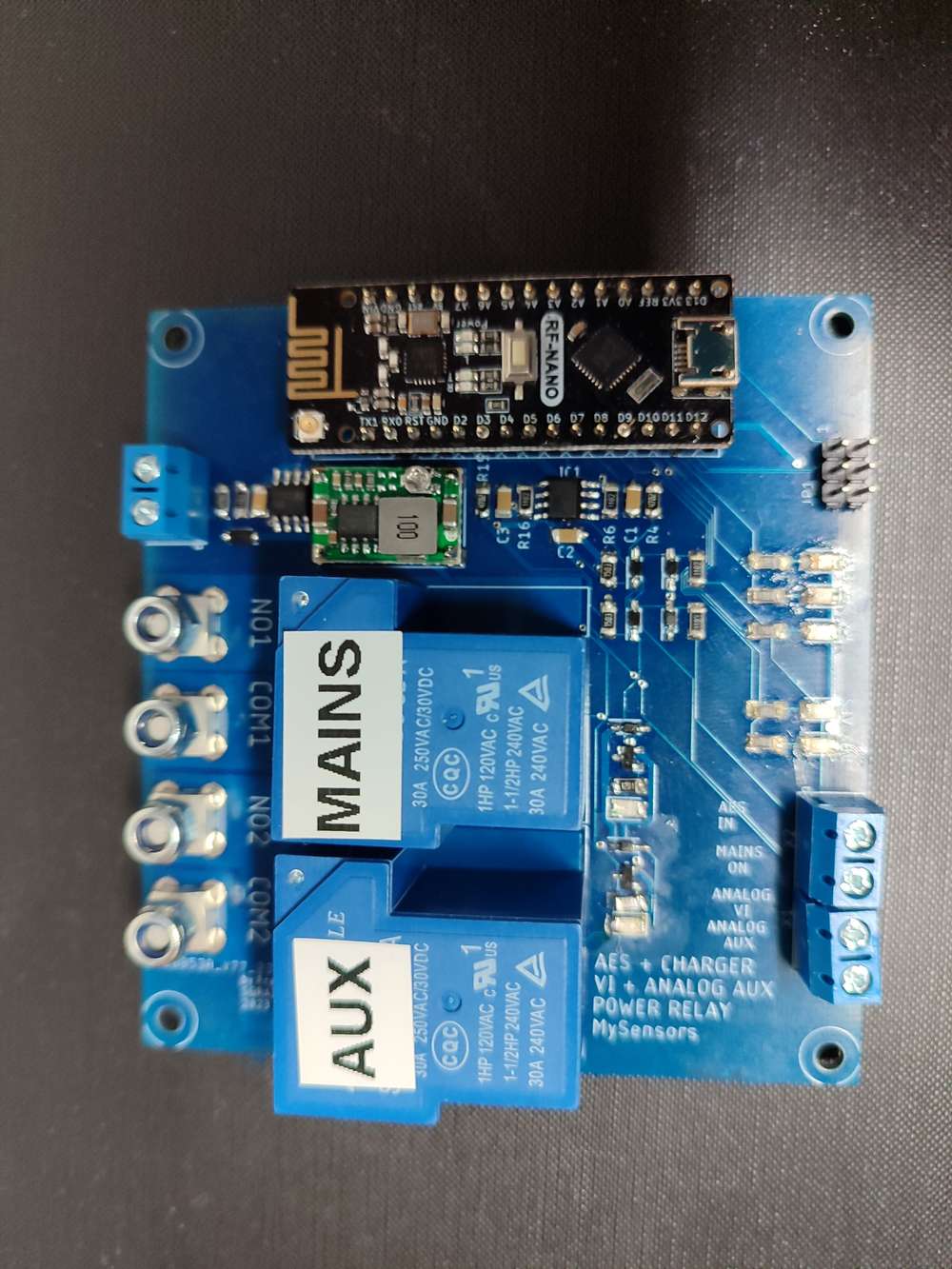
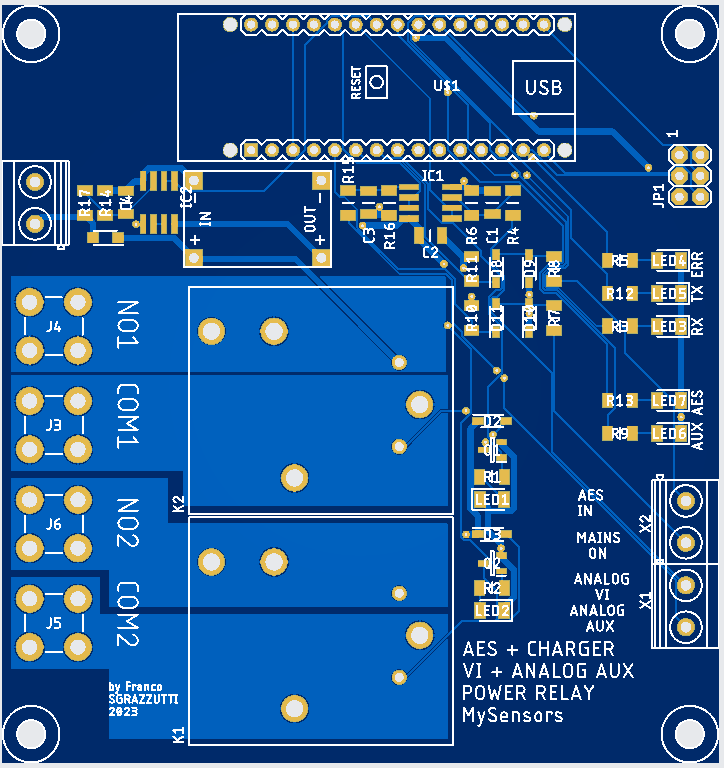
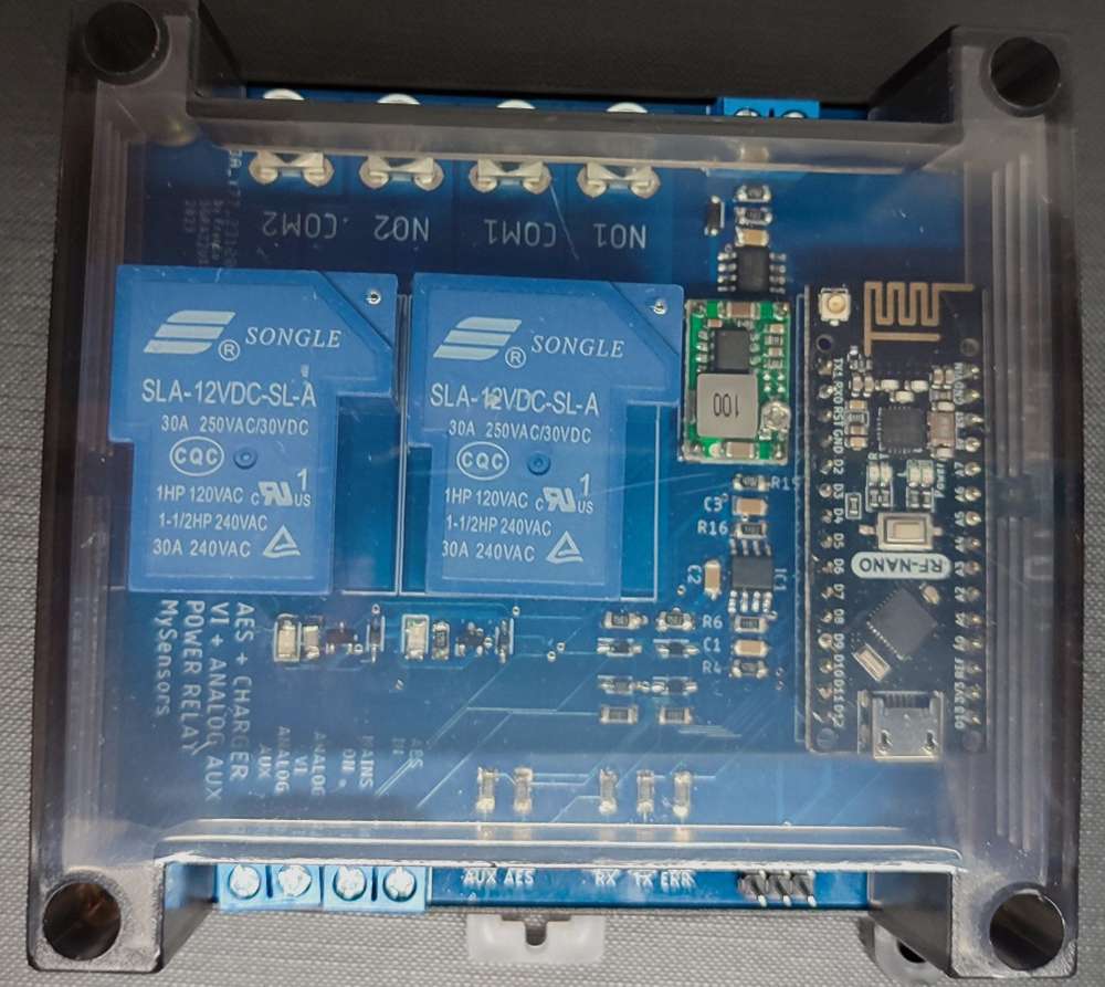
Auxiliary Loads and Mains Charger Controller for my Smart Mobile HomeA simple node to enable/disable the 12V power supply to auxiliary non vital loads (e.g. water boiler) based on the service battery voltage. A relay is controlled by the presence of a charging source.
Additionally, in presence of other charge sources, the Mains Charger is disconnected from the Service Battery. The Mains Charger relay is enabled if there are no other charge sources and the camper is connected to the Shore Power.There are 2 additional analog voltage input.
I tend to create edge nodes, with full capability of serving the desired use cases, even if Gateway/Controller are down. In this case I can Arm/Disarm some automations from the controller using S_DOOR sensor types.
-
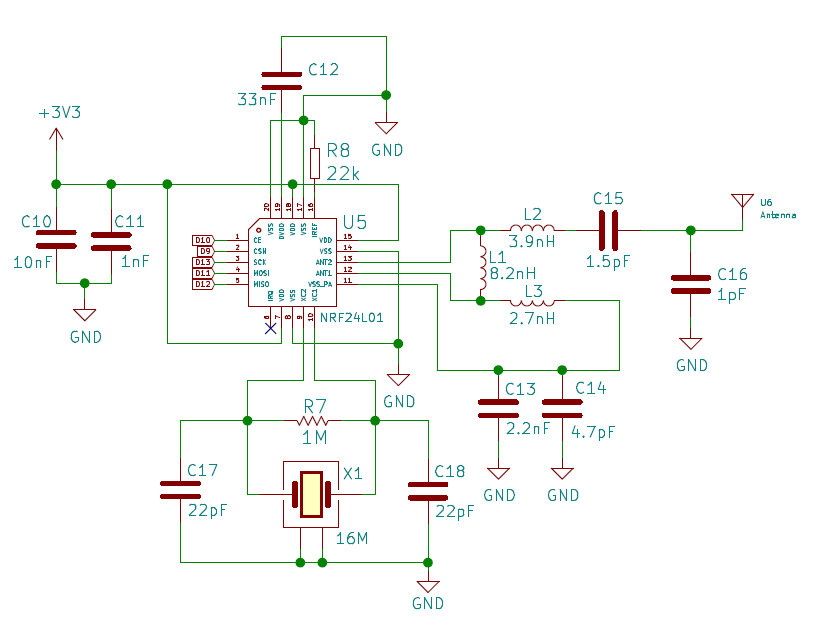
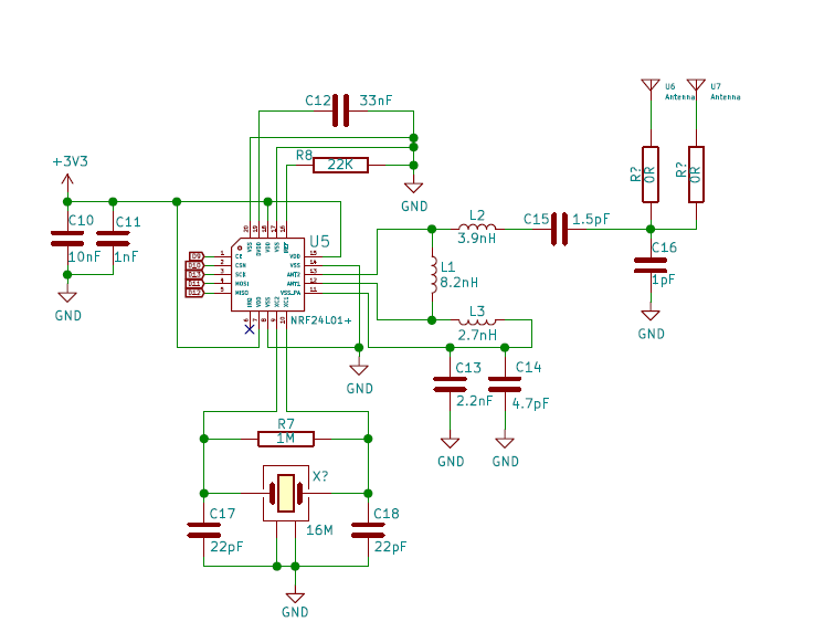
RF Nano = Nano + NRF24, for just $3,50 on AliexpressHello,
I use the RF-NANO widely in my sensors. At the beginning of the year I reordered 10 pcs and I got the new version.
I discovered that between V1 (bought in 2019) and V2 (bought in 2020) D9 and D10 are reversed between the 2 versions.V1
V2
links:
https://github.com/emakefun/emakefun-nano-plus/blob/master/RF-Nano/Schematic/RF-Nano-Schematic.pdf
https://github.com/emakefun/rf-nano/blob/master/RF-Nano-Schematic.pdfHope it helps.
Franco -
ESP WiFi hung solutionThis is how I solved the issue of ESP32 GW hanging when WiFi connection is lost or not established. It is not 100% my original work, it has been put together using bits and pieces, but it works.
I simply use a watchdog timer:
#include "esp_system.h" // added for WDT
hw_timer_t* timer = NULL;

// WDT related
void IRAM_ATTR resetModule() {
	Serial.println("reboot\n");
	ESP.restart();
}

void WdtReset()
{
    timerWrite(timer, 0); //reset timer (feed watchdog)
}

void StartWatchDog()
{
    timer = timerBegin(0, 240, true); //timer 0, div 80
    timerAttachInterrupt(timer, &resetModule, true);
    timerAlarmWrite(timer, 5000000, false); //set time in us
    timerAlarmEnable(timer); //enable interrupt
}

IPAddress ConnectWiFi()
{
    Serial.println();
    Serial.println();
    Serial.print("Connecting to ");
    Serial.println(MY_WIFI_SSID);

    /* Explicitly set the ESP to be a WiFi-client, otherwise, it by default,
       would try to act as both a client and an access-point and could cause
       network-issues with your other WiFi-devices on your WiFi-network. */
#ifdef ESP32
    WiFi.persistent(false);
    WiFi.mode(WIFI_STA);
#endif // ESP32

    WiFi.begin(MY_WIFI_SSID, MY_WIFI_PASSWORD);


    while (WiFi.status() != WL_CONNECTED) {
        digitalWrite(LED_BUILTIN, LED_ON);
        wait(500);
        Serial.print(".");
        digitalWrite(LED_BUILTIN, LED_OFF);
        wait(500);
    }

#ifdef ESP32
    WiFi.setAutoReconnect(true);
#endif // ESP32

    return WiFi.localIP();

}
void before()
{

    StartWatchDog();

    // We start by connecting to a WiFi network
    localIP = ConnectWiFi();
    myHostname = WiFi.getHostname();

    WdtReset();

    Serial.println("");
    Serial.println("WiFi connected");
    Serial.println("IP address: ");
    Serial.println(localIP);
    Serial.println(myHostname);

// do other stuff ...

}

void loop()
{


    // check WiFi connection
    if (WiFi.status() != WL_CONNECTED) return; // the WDT is not reset
    WdtReset();

// do other stuff ...
}
Hope it helps
-
Alexa Fauxmo - Mysensor Bridge Gateway / BLE - Mysensors Bridge GatewayIn my RV I use #mysensors and #mycontroller V1.
A few times I wished I could switch on/off remotely a few subsystems (water, solar, geofencing and alarms to name a few) without needing to access mycontroller from remote.
So I took off from my ideas shelf an old experiment with Fauxmo and Alexa Echo Dot gen 3.
Alexa Echo Dot embeds a WiFi gateway for Hue lights. Fauxmo Arduino library allows to fake these lamps, and works on ESP8266 and ESP32. Perfect for our MySensors.
So I simply created a Mysensors Gateway with 16 Dimmer local sensors, and added the Fauxmo library and created 16 fake ("faux") lamp devices.
When an Alexa event is detected, and the event send()s the lamp status to the controller.
When the GW receive()s a dimmer sensor event from the controller, the dimmer state is sent to Alexa.Alexa needs to receive a device update at least every minute, so a simple software timer in the loop() is in charge for this.
A couple of years ago I created a BLE - Mysensors Gateway which scans my Gas Tank sensors over BLE and sends the sensors data to the Controller.
Both projects consist of ESP32 dev boards without any additional HW, in a nice and simple 3D printed enclosure bought on Ebay.
-
Status of my rv(camper) home automation system 2020-2025I'd like to share with you the figures after 6 years of dedicated work to my system:
controller: #mycontroller v1
database: influxDB v.1.8
visualisation: grafana v.9.3.2
events and mobile UI: node-red
peer-to-peer VPN: ZeroTier One5 gateways
3 displays
52 nodes
392 sensors935 sensor data/minute
Hardware:
Beelink SLIM-T4PRO Windows 10 Pro
ESP32
Arduino Nano
Arduino RF-Nano
Arduino Mini
Radio nRF24L01+
Mobile router Teltonika RUT241 E-SIMThank you MySensors !
-
Some questions on how gateway works@mfalkvidd thanks.
I am happily running 6 esp32 WiFi gateways with nRF24L01+, but with the mysensors serial protocol, not mqtt. I don't see any value on MQTT for a local system based entirely on mysensors like mine, but I might be wrong and don't see the potential.
I have a couple of them working as bridges, like between BLE sensors and mysensors, or Alexa an mysensors, meteo RSS Feed etc.
-
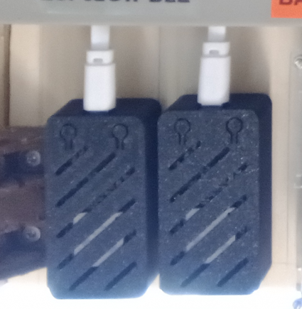
Project enclosuresThis is my temperature-humidity-pressure sensor in a 1151v3wh enclosure.
-
Time to move to ESPHome?I needed to add my Victron devices to mycontroller v1, so I've created a Esphome device that includes the Victrons and 2 Mopeka Tank Pro devices, all via BLE Advertisement
Playing around with the topics, I have been able to declare a node name/id for each of these BLE devices.
each BLE device has a node name/id, childs name/id.sensor example:
sensor:
----------------------------------------------------------
Victron IP22
----------------------------------------------------------
- platform: victron_ble
victron_ble_id: victron_ip22
name: "mains_charger_voltage"
id: mains_charger_voltage
type: BATTERY_VOLTAGE
state_topic: "${mys_prefix}/${mys_gateway}/${node_victron_ip22}/${child_victron_voltage}/${C_SET}/${mys_ack}/${V_VOLTAGE}"
on mycontroller I've created a mysensors mqtt virtual gateway, and voila'.
from now on I can use Esphome to create other nodes, also in separate devices. I just need to keep track of the used node ids, that must be static.
Node and sensors presentation is handled as well
- platform: victron_ble