I needed to add my Victron devices to mycontroller v1, so I've created a Esphome device that includes the Victrons and 2 Mopeka Tank Pro devices, all via BLE Advertisement
Playing around with the topics, I have been able to declare a node name/id for each of these BLE devices.
each BLE device has a node name/id, childs name/id.
sensor example:
sensor:
----------------------------------------------------------
Victron IP22
----------------------------------------------------------
- platform: victron_ble
victron_ble_id: victron_ip22
name: "mains_charger_voltage"
id: mains_charger_voltage
type: BATTERY_VOLTAGE
state_topic: "${mys_prefix}/${mys_gateway}/${node_victron_ip22}/${child_victron_voltage}/${C_SET}/${mys_ack}/${V_VOLTAGE}"
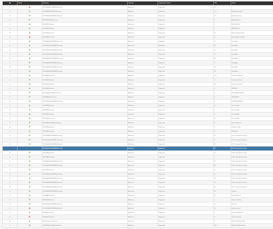
on mycontroller I've created a mysensors mqtt virtual gateway, and voila'.
from now on I can use Esphome to create other nodes, also in separate devices. I just need to keep track of the used node ids, that must be static.
Node and sensors presentation is handled as well