@Nigel31 glad you got a fix :+1:
GardenShedDev
@GardenShedDev
Posts
-
Sudden Dead node, and consequent !TSM:FPAR:NO REPLY -
Sudden Dead node, and consequent !TSM:FPAR:NO REPLYI have had a similar problem with a couple of my nodes working perfect one day and dead the next.
I am not saying your problem is the same as what I have experienced but I had issues with the cheap pro minis particularly the smoothing caps on the Vcc side that basically turned into resistors and dragged down the battery etc etc…
It’s not uncommon for capacitors to do this after a number of years of use, but it a little strange to do this after a little over a year. That said my boards are Chinese clones which will likely be using the lowest cost and quality parts which they could find - as they say you get what you pay for!
I resolved my problem by tracing the caps on the Vcc and desoldered them and replaced with an good old fashioned electrolytic capacitor soldered onto the Vcc and Gnd pins, not pretty but it works.
If you have a spare pro mini or RFM69 I would start by simply swapping the boards out to see if the problem gets resolved or moves with the board swap - it’s not going to fix the problem but it will hopefully help you to localise the problem to one or the other boards.
-
ESP8266 OTA and Arduino IDE What Am I Missing?@mfalkvidd - your response got me thinking about my question some more - the effort required to diagnose/ rework would for little gain, i am thinking its simpler to rework the psu and seperate the NRF from the ESP - its likley that the ESP regulator is only spec'd to power the ESP and not a lot else - lets face it we are not dealing with miltary grade components here lol :)
Thanks for the help and support!
-
ESP8266 OTA and Arduino IDE What Am I Missing?Some good news and progress!!
Seems like the NRF power consumption was indeed the culprit. Disabling the NRF in the software didnt do the trick, however when I disconected the power to the module and restarted, after about 10 minutes it appeared in the IDE Network Ports section and I can upload sketches over OTA.
As a result I have trimmed down the connector leads to 2 inches, which still works in my enclosure, added another 10uF cap across the ESP regulator and replaced the one strapped across the NRF module. I have lost all the 'bounces' in the debug log from the ESP and the OTA is available straight away every time the board is power cycled. I wont know for sure until I can get my scope out of storage but I suspect that the original 10uF Cap had become more of a resistor than a capacitor with use over the last 2 years - one for the list during down time over xmas :)
So while I have a fix, the elephant in the room is why did the Arduino OTA sketch work and why did the MYS OTA sketch not work?!?!?!
Does the MYS OTA sketch handle power/ comms/ timing in a different way to the Arduino OTA sketch which could cause this problem? or, Is it a timing thing and by this I mean is it a race condition on the power between the ESP core working through its startup and the sketch and the NRF turning on and the causing the power to bounce?
-
ESP8266 OTA and Arduino IDE What Am I Missing?Yes it is connected, the psu bumps a little and then settles down when initially turned on (despite having extra capacitors strapped to the NRF and ESP) and then starts communicating as expected. I suspect its to do with the length of the leads and the thickness connecting the nrf to the esp, I either need to shorten the leads or put thicker ones in place to compensate for the v drop.
Funny thing is tthe HW 'as' configured works for Arduino OTA but not the MYS OTA?!?!
-
ESP8266 OTA and Arduino IDE What Am I Missing?@mfalkvidd heres a typical output from the gateway serial. Just did a power cycle and captured the startup and then a couple of transactions at the end;
scandone
state: 0 -> 2 (b0)
state: 2 -> 3 (0)
state: 3 -> 5 (10)
add 0
aid 4
cnt

connected with MYSSIDxxx, channel 1
ip:192.168.x.x,mask:255.255.255.0,gw:192.168.x.x
ip:192.168.x.x,mask:255.255.255.0,gw:192.168.x.x
3231 GWT:TPC:IP=192.168.x.x
3396 GWT:RMQ:CONNECTING...
3441 GWT:RMQ:OK
3458 GWT:TPS:TOPIC=mygateway1-out/0/255/0/0/18,MSG SENT
3948 GWT:IMQ:TOPIC=mygateway1-in/3/4/1/0/30, MSG RECEIVED
4045 !TSF:MSG:SEND,0-0-67-3,s=4,c=1,t=30,pt=0,l=1,sg=0,ft=0,st=NACK:1
4118 GWT:IMQ:TOPIC=mygateway1-in/3/4/1/0/29, MSG RECEIVED
4215 !TSF:MSG:SEND,0-0-67-3,s=4,c=1,t=29,pt=0,l=1,sg=0,ft=0,st=NACK:1
4289 GWT:IMQ:TOPIC=mygateway1-in/3/4/1/1/30, MSG RECEIVED
4385 !TSF:MSG:SEND,0-0-67-3,s=4,c=1,t=30,pt=0,l=1,sg=0,ft=0,st=NACK:1
4459 GWT:IMQ:TOPIC=mygateway1-in/3/255/3/0/6, MSG RECEIVED
4556 !TSF:MSG:SEND,0-0-67-3,s=255,c=3,t=6,pt=0,l=1,sg=0,ft=0,st=NACK:M
4630 GWT:IMQ:TOPIC=mygateway1-in/7/255/3/0/6, MSG RECEIVED
4728 !TSF:MSG:SEND,0-0-7-7,s=255,c=3,t=6,pt=0,l=1,sg=0,ft=0,st=NACK:M
4802 GWT:IMQ:TOPIC=mygateway1-in/9/255/3/0/6, MSG RECEIVED
4899 !TSF:MSG:SEND,0-0-9-9,s=255,c=3,t=6,pt=0,l=1,sg=0,ft=0,st=NACK:M
4972 GWT:IMQ:TOPIC=mygateway1-in/8/255/3/0/6, MSG RECEIVED
5070 !TSF:MSG:SEND,0-0-8-8,s=255,c=3,t=6,pt=0,l=1,sg=0,ft=0,st=NACK:M
5143 GWT:IMQ:TOPIC=mygateway1-in/6/255/3/0/6, MSG RECEIVED
5241 !TSF:MSG:SEND,0-0-6-6,s=255,c=3,t=6,pt=0,l=1,sg=0,ft=0,st=NACK:M
5314 GWT:IMQ:TOPIC=mygateway1-in/4/255/3/0/6, MSG RECEIVED
5412 !TSF:MSG:SEND,0-0-4-4,s=255,c=3,t=6,pt=0,l=1,sg=0,ft=0,st=NACK:M
5485 GWT:IMQ:TOPIC=mygateway1-in/2/255/3/0/6, MSG RECEIVED
5583 !TSF:MSG:SEND,0-0-2-2,s=255,c=3,t=6,pt=0,l=1,sg=0,ft=0,st=NACK:M
7725 TSF:MSG:READ,7-7-255,s=255,c=3,t=7,pt=0,l=0,sg=0:
7782 TSF:MSG:BC
7799 TSF:MSG:FPAR REQ,ID=7
7827 TSF:CKU:OK,FCTRL
7850 TSF:MSG:GWL OK
8576 TSF:MSG:SEND,0-0-7-7,s=255,c=3,t=8,pt=1,l=1,sg=0,ft=0,st=OK:0
8646 TSF:MSG:READ,4-4-0,s=1,c=1,t=0,pt=7,l=5,sg=0:19.6
8704 GWT:TPS:TOPIC=mygateway1-out/4/1/1/0/0,MSG SENT
8761 TSF:MSG:READ,4-4-0,s=2,c=1,t=1,pt=7,l=5,sg=0:69.1
8819 GWT:TPS:TOPIC=mygateway1-out/4/2/1/0/1,MSG SENT
8875 TSF:MSG:READ,4-4-0,s=4,c=1,t=0,pt=7,l=5,sg=0:19.4
8933 GWT:TPS:TOPIC=mygateway1-out/4/4/1/0/0,MSG SENT
9481 TSF:MSG:READ,4-4-0,s=3,c=1,t=37,pt=7,l=5,sg=0:0.0
9538 GWT:TPS:TOPIC=mygateway1-out/4/3/1/0/37,MSG SENT
9797 TSF:MSG:READ,7-7-0,s=255,c=3,t=24,pt=1,l=1,sg=0:1
9855 TSF:MSG:PINGED,ID=7,HP=1
9893 TSF:MSG:SEND,0-0-7-7,s=255,c=3,t=25,pt=1,l=1,sg=0,ft=0,st=OK:1
10024 TSF:MSG:READ,4-4-0,s=255,c=3,t=0,pt=1,l=1,sg=0:12
10083 GWT:TPS:TOPIC=mygateway1-out/4/255/3/0/0,MSG SENT
10532 TSF:MSG:READ,4-4-0,s=5,c=1,t=38,pt=7,l=5,sg=0:1.7
10591 GWT:TPS:TOPIC=mygateway1-out/4/5/1/0/38,MSG SENT
11043 TSF:MSG:READ,4-4-0,s=6,c=1,t=38,pt=7,l=5,sg=0:510.0
11103 GWT:TPS:TOPIC=mygateway1-out/4/6/1/0/38,MSG SENT
pm open,type:2 0
17013 TSF:MSG:READ,7-7-0,s=255,c=3,t=0,pt=1,l=1,sg=0:43
17072 GWT:TPS:TOPIC=mygateway1-out/7/255/3/0/0,MSG SENT
17527 TSF:MSG:READ,7-7-0,s=5,c=1,t=38,pt=7,l=5,sg=0:2.4
17586 GWT:TPS:TOPIC=mygateway1-out/7/5/1/0/38,MSG SENT
18040 TSF:MSG:READ,7-7-0,s=6,c=1,t=38,pt=7,l=5,sg=0:730.0
18101 GWT:TPS:TOPIC=mygateway1-out/7/6/1/0/38,MSG SENT
20697 TSF:MSG:READ,7-7-0,s=4,c=1,t=19,pt=7,l=5,sg=0:3.0
20756 GWT:TPS:TOPIC=mygateway1-out/7/4/1/0/19,MSG SENT
21211 TSF:MSG:READ,7-7-0,s=4,c=1,t=19,pt=7,l=5,sg=0:0.0
Just to make doubly sure I addded
Serial.print("SETUP MESSAGE TEST PRINT"); to the setup part of the sketch
and here is the revised log snippet;
87 GWT:TPC:CONNECTING... 1421 MCO:BGN:STP SETUP MESSAGE TEST PRINTReady IP address: 192.168.x.x 1441 MCO:BGN:INIT OK,TSP=1 1529 TSM:READY:NWD REQ 1556 ?TSF:MSG:SEND,0-0-255-255,s=255,c=3,t=20,pt=0,l=0,sg=0,ft=0,st=OK: scandone state: 0 -> 2 (b0) state: 2 -> 3 (0) state: 3 -> 5 (10) add 0 aid 4 cnt -
ESP8266 OTA and Arduino IDE What Am I Missing?@BearWithBeard Thank you for having a look into this!!!
I retried minus the yield() - still doesnt work (its the only combination I havent actually tried upto this point!!) - also yes I can ping the device on the network.
I am running Arduino IDE 1.8.13, I have tried restarting, gone to another laptop (windows) as I run OSX, waited a minute, an hour, 3 hours, no joy with the MYS OTA.
When I use the Arduino OTA everything works as it should, the board shows up in the Ports menu straight away.
Through process of elimination its not a HW related problem (ESP or network), but I do definitley think its a SW problem specific to the MYS library.
This has got me thinking a little, I am going to recompile the sketch using the windows laptop to see if this works - my thinking being there may be a library problem on the mac.
Im going to swerve platformio at the moment but it does look intriguing so im going have a look at this in down time over the next few weeks :)
-
ESP8266 OTA and Arduino IDE What Am I Missing?@mfalkvidd Have tried downgrading to 2.3.1, at which point the compiler has thrown a shed load of errors, so reinstated the library back to 2.3.2.
I have also worked in my code from my working ArduinoOTA sketch, still not working....?!?!
-
ESP8266 OTA and Arduino IDE What Am I Missing?@mfalkvidd running 2.3.2
-
ESP8266 OTA and Arduino IDE What Am I Missing?@mfalkvidd - checked with the Arduino OTA and it works as it should and appeared straight away in the network ports section of the Arduino IDE.
I went one step further and succesfully re-uploaded the gateway sketch over the Arduino OTA, however, as before the Gateway Sketch OTA doesnt work.
Ok, so this is a step forward as I now know that its not a HW problem - its definitely a SW problem
-
ESP8266 OTA and Arduino IDE What Am I Missing?@mfalkvidd - No, i havent tried this specific ESP8266 to ensure the Arduino OTA sketch works BUT I do have 5 other devices on the network all using Arduino OTA and they work fine.
For the 20 minutes it will take me to flash the programs in I will check it to rule out the HW
-
ESP8266 OTA and Arduino IDE What Am I Missing?@mfalkvidd - random thought (and clutching at straws now) does it make a difference on where the includes are placed and the definitions?
The reason I ask is that you have #include <ArduinoOTA.h> at the top of the file then your definitions followed by your includes - i know this is important for MYS just wondering if this is the same for the ArduinoOTA.h when used with MYS? Thoughts?
-
ESP8266 OTA and Arduino IDE What Am I Missing?@mfalkvidd thanks or that - spent an hour or so refactoring the code to be similar to yours, dhcp address rather than static, ensure all the includes are the same, added MY_USE_UDP and the WiFiUdp.h include etc etc, tried from a windows pc instead of mac, I have even put in the additional ESP OTA include in ESP8266mDNS (this threw a compile error - figure its not compatible with MYS) net result - nothing, it still doesnt show up!!!
I have a spare ESP kicking around I might try swapping it over just to make sure there is nothing screwy going on with the HW!
That said, I feel like I am missing something obvious - but I am not sure where to go next?!?!?
-
ESP8266 OTA and Arduino IDE What Am I Missing?Apologies upfront if this has already been asked and worked out but I cannot find the answer in the forum or a good working example.
I have been running MySensors for a few years now with no OTA, I have decided I want to enable it for my gateway only. For simplicity I want to use ESP8266 OTA and avoid custom booloaders for the ESP8266.
I have used the ESP8266ota example sketch as the base and tweaked - see below - the sketch compiles and the gateway works - but - the gateway device cannot found in the network ports section in the Arduino IDE - although my other ESPs are present?!?!?
I know that there are differences between a standard ESP8266 OTA and the MySensors OTA version but I am not sure what, if anything I am missing in the my sensors variant?
// Enable debug prints to serial monitor #define MY_DEBUG // Use a bit lower baudrate for serial prints on ESP8266 than default in MyConfig.h #define MY_BAUD_RATE 9600 // Enables and select radio type (if attached) #define MY_RADIO_RF24 //#define MY_RADIO_RFM69 //#define MY_RADIO_RFM95 #define MY_GATEWAY_MQTT_CLIENT #define MY_GATEWAY_ESP8266 // Set WIFI SSID and password #define MY_WIFI_SSID "SSID" #define MY_WIFI_PASSWORD "password" // Set this node's subscribe and publish topic prefix #define MY_MQTT_PUBLISH_TOPIC_PREFIX "mygateway1-out" #define MY_MQTT_SUBSCRIBE_TOPIC_PREFIX "mygateway1-in" // Set MQTT client id #define MY_MQTT_CLIENT_ID "mysensors-1" // Enable these if your MQTT broker requires username/password #define MY_MQTT_USER "user" #define MY_MQTT_PASSWORD "password" // Controller ip address. Enables client mode (default is "server" mode). // Also enable this if MY_USE_UDP is used and you want sensor data sent somewhere. // MQTT broker ip address. #define MY_CONTROLLER_IP_ADDRESS 192,168,0,1 // The port to keep open on node server mode // The MQTT broker port to to open #define MY_PORT 1883 // Set the hostname for the WiFi Client. This is the hostname // passed to the DHCP server if not static. #define MY_HOSTNAME "MYS_GW" // Enable UDP communication //#define MY_USE_UDP // If using UDP you need to set MY_CONTROLLER_IP_ADDRESS below // Enable MY_IP_ADDRESS here if you want a static ip address (no DHCP) #define MY_IP_ADDRESS 192,168,0,2 // If using static ip you can define Gateway and Subnet address as well #define MY_IP_GATEWAY_ADDRESS 192,168,0,1 #define MY_IP_SUBNET_ADDRESS 255,255,255,0 // How many clients should be able to connect to this gateway (default 1) //#define MY_GATEWAY_MAX_CLIENTS 2 // Enable inclusion mode //#define MY_INCLUSION_MODE_FEATURE // Enable Inclusion mode button on gateway //#define MY_INCLUSION_BUTTON_FEATURE // Set inclusion mode duration (in seconds) //#define MY_INCLUSION_MODE_DURATION 60 // Digital pin used for inclusion mode button //#define MY_INCLUSION_MODE_BUTTON_PIN 3 // Set blinking period // #define MY_DEFAULT_LED_BLINK_PERIOD 300 // Flash leds on rx/tx/err // Led pins used if blinking feature is enabled above //#define MY_DEFAULT_ERR_LED_PIN 16 // Error led pin //#define MY_DEFAULT_RX_LED_PIN 16 // Receive led pin //#define MY_DEFAULT_TX_LED_PIN 16 // the PCB, on board LED #include <ArduinoOTA.h> #include <MySensors.h> void setup() { // Setup locally attached sensors ArduinoOTA.onStart([]() { Serial.println("ArduinoOTA start"); }); ArduinoOTA.onEnd([]() { Serial.println("\nArduinoOTA end"); }); ArduinoOTA.onProgress([](unsigned int progress, unsigned int total) { Serial.printf("OTA Progress: %u%%\r", (progress / (total / 100))); }); ArduinoOTA.onError([](ota_error_t error) { Serial.printf("Error[%u]: ", error); if (error == OTA_AUTH_ERROR) { Serial.println("Auth Failed"); } else if (error == OTA_BEGIN_ERROR) { Serial.println("Begin Failed"); } else if (error == OTA_CONNECT_ERROR) { Serial.println("Connect Failed"); } else if (error == OTA_RECEIVE_ERROR) { Serial.println("Receive Failed"); } else if (error == OTA_END_ERROR) { Serial.println("End Failed"); } }); ArduinoOTA.begin(); } void presentation() { // Present locally attached sensors here } void loop() { // Send locally attached sensors data here ArduinoOTA.handle(); yield(); //let the ESP do some internal work } -
[Solved]ProMini Will Not Sleep/ Enter Low Power Mode - what is best avr sleep or smartsleep?ok, so I figured it out... and just recording my observatios and fix in the hope it helps others or me if I forget :)
@yveaux and @zboblamont said to use the MyS sleep() function which can handle interupts on pins 2 & 3. For me this is too limitiing as I am using 4 pins.
What I needed was something simple for a rapid build. When I intially built the node a month ago I read up on the MyS sleep function, realised that it couldnt handle more than 2 pins for interupts and opted to go down the route of interupts as laid out on www.gammon.com.au. After a little more reading I then implemented the AVR sleep function, so far so good or so I thought - move fwd to my problem. While everything was working well:
- scene controller HW built - check,
- Software created - check,
- Enclosure printed - check,
- hooked up to home assitant - check,
- WAF (very important) - check,
...the node wasnt actaully sleeping DOH!
Upto this point I had spent less than 6 hours in dev and implementation time....
So heres the problem, after a lot of reading over the last 36 hours I found a post that states MyS library only implements interupts for pins 2&3 on the pro mini - it doesnt implement interupt groups such as PCINT1 (A0-A5) etc AND the node cannot be woken up via interupt if it is not done via pins 2&3.
@electrik posted a link to his excellent sketch that hacks the core code a little - as I was looking into this method I stumbled on a post by @freynder that implements a 'dirty hack' here which forces the node to wake up on interupt when using the MyS sleep() function. This then led me to a post on a 6/8 button controller here. These two posts have be pivotal in fixing my problem. Thank you @electrik for triggering the thought process that lead to a simple solution :)
@yveaux and @zboblamont you where both correct I need to use the MyS sleep() function which I have now implemented alongside the external interupt library form the 6/8 button controller link and the added the two lines of code as per the 'dirty hack'
My node now reads 18mA when active (transmitting) and when sleeping it is less than 0.5mA - which is the limitation of my equipment!
@zboblamont to answer your Q about node setup, I have a pro mini and with both the power led and regulator removed as per the MySensors hack for battery nodes - however the transmit led is still connected which will draw extra current when transmitting, which I am ok with for the moment lol
thank you to all that have contributed !!
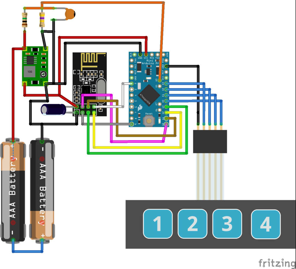
heres the schematic of the controller:
and an updated extract of the code#define MY_DEBUG true // Enable debug prints #define MY_RADIO_NRF24 // Enable and select radio type attached #define MY_NODE_ID 7 // >>>>>>>>Set the node ID manually - this must be set the mysensors.h call<<<<<<<<<<<<<<<<<<<<<<<<<<<<<<<< #include <MySensors.h> #include <OneButton.h> // https://github.com/mathertel/OneButton #define EI_NOTEXTERNAL // External interrupts managed by built-in routines #include <EnableInterrupt.h> // Pin-change interrupts #define MIN_V 1.9 // Minimum Battery Voltage #define MAX_V 3.1 // Max Battery Voltage #define CHILD_ID_BUTTON1 1 #define CHILD_ID_BUTTON2 2 #define CHILD_ID_BUTTON3 3 #define CHILD_ID_BUTTON4 4 #define CHILD_ID_BATTERY 5 #define CHILD_ID_ADC 6 #define SN "Scene Controller" #define SV "0.4" #define BUTTON4 A1 // Interput pin and button definitions #define BUTTON1 A2 #define BUTTON3 A0 #define BUTTON2 A3 OneButton button4(BUTTON4, true); // Setup a new OneButton on pin A1. OneButton button1(BUTTON1, true); // Setup a new OneButton on pin A2. OneButton button3(BUTTON3, true); // Setup a new OneButton on pin A0. OneButton button2(BUTTON2, true); // Setup a new OneButton on pin A3. int SendDelay = 500; // Time to wait before sending data over the radio int BATTERY_SENSE_PIN = A5; // Define battery sense pins int oldBatteryPcnt = 0; //int batteryCounter = BATTERY_REPORT_CYCLE -1; // counter for battery update //int reportCounter = FORCE_TRANSMIT_CYCLE -1; // counter for the loop and forcing updates unsigned long StartTime = 0; // sleep startime variable unsigned long SleepWaitTime = 10000; // Time to wait before going to sleep 10 seconds unsigned long Sleep_Time = 86400000; // 86400000 Sleep for 24 hours int MessageA = 0; // Button Message Values 0- no value int MessageB = 1; // up int MessageC = 2; // down int MessageD = 3; // toggle on/off MyMessage msgButton1(CHILD_ID_BUTTON1, V_SCENE_ON); MyMessage msgButton2(CHILD_ID_BUTTON2, V_SCENE_ON); MyMessage msgButton3(CHILD_ID_BUTTON3, V_SCENE_ON); MyMessage msgButton4(CHILD_ID_BUTTON4, V_SCENE_ON); MyMessage msgBattery(CHILD_ID_BATTERY, V_VOLTAGE); MyMessage msgADCValue(CHILD_ID_ADC, V_VOLTAGE); /* #################################################### # # # Presentaion # # # #################################################### */ void presentation() { sendSketchInfo(SN, SV); wait(SendDelay); // Send the sketch version information to the gateway present(CHILD_ID_BUTTON1, S_SCENE_CONTROLLER); wait(SendDelay); // Register all sensors to gw (they will be created as child devices) present(CHILD_ID_BUTTON2, S_SCENE_CONTROLLER); wait(SendDelay); present(CHILD_ID_BUTTON3, S_SCENE_CONTROLLER); wait(SendDelay); present(CHILD_ID_BUTTON4, S_SCENE_CONTROLLER); wait(SendDelay); present(CHILD_ID_BATTERY, S_MULTIMETER); wait(SendDelay); present(CHILD_ID_ADC, S_MULTIMETER); wait(SendDelay); // metric = getControllerConfig().isMetric; } /* #################################################### # # # Void Setup # # # #################################################### */ void setup() { analogReference(INTERNAL); Serial.begin(115200); // Setup the Serial port. see http://arduino.cc/en/Serial/IfSerial Serial.println("Starting..."); delay(10); button1.attachClick(click1); // Button 1 functions. button1.attachDoubleClick(doubleclick1); button1.attachLongPressStop(longPressStop1); button2.attachClick(click2); // Button 2 functions. button2.attachDoubleClick(doubleclick2); button2.attachLongPressStop(longPressStop2); button3.attachClick(click3); // Button 3 functions. button3.attachDoubleClick(doubleclick3); button3.attachLongPressStop(longPressStop3); button4.attachClick(click4); // Button 4 functions. button4.attachDoubleClick(doubleclick4); button4.attachLongPressStop(longPressStop4); enableInterrupt(BUTTON1,Int_vect,CHANGE); enableInterrupt(BUTTON2,Int_vect,CHANGE); enableInterrupt(BUTTON3,Int_vect,CHANGE); enableInterrupt(BUTTON4,Int_vect,CHANGE); } /* #################################################### # # # Void Loop # # # #################################################### */ void loop() { if((millis() - StartTime) >= SleepWaitTime) // Wait for some time before going to sleep { Serial.println("Sleeping...."); delay(10); sleep(Sleep_Time); // Sleepy Time :) // WAKE UP HERE _wokeUpByInterrupt = INVALID_INTERRUPT_NUM; //dirty hack wake up routine - clear interupt StartTime = millis(); Serial.println("Awake..."); int battery_read; // call function - Send the battery status battery_read = SendBattery(); } button1.tick(); // Check the push buttons: button2.tick(); button3.tick(); button4.tick(); delay(10); } /* #################################################### # # # Interupt Service Routine # # # #################################################### */ void Int_vect() // handle pin change interrupt for A0 to A5 here { //Serial.println("--**-INTERRUPT-**--"); //debug _wokeUpByInterrupt = 0xFE; // Dirty hack to get out of MySensors sleep loop } -
[Solved]ProMini Will Not Sleep/ Enter Low Power Mode - what is best avr sleep or smartsleep?@electrik I assume the example if for an earlier version of MySensors 1.x - is this method still valid for 2.x onwards?
-
[Solved]ProMini Will Not Sleep/ Enter Low Power Mode - what is best avr sleep or smartsleep?Thank you for the reply
I am using 4 pins/ switches that I need to monitor
Is it possible to use PCINT1 for the interupt definition (pin change) when using the mysensors sleep() method or does it have to be definined as pin 2 and 3 only?
update: answering my own question no its not possible - while a sketch compiles using the PCINT1 it does not wake up the device
-
[Solved]ProMini Will Not Sleep/ Enter Low Power Mode - what is best avr sleep or smartsleep?I have created a very simple 4 button battery powered scene controller using a promini, an nrf24, 4 button membrane keypad and 2xAAA.
On intial run the device regeisters itself then after a short period it goes to sleep and stays asleep until a button ispressed. I use interupts on PCINT1 (4 pins) to wake up the device and transmit the subsequent scene ID which works really well - however- after 3 weeks of use the batterys died and then I realised that the promini wasnt actaully going to sleep which means not powering down.
When transmitting the device consumes 18mA, in 'so called' sleep mode it consumes 14mA.
I suspect that I am not putting the promini to sleep correctly within the MySensors framework - I have put an extract of my sketch below - can someone check the sleep mode calls and let me know if im doing something wrong?
Thx
Sleep Routine:
void loop()
  {
    if((millis() - StartTime) >= SleepWaitTime)   // Wait for some time before going to sleep
      {
        Serial.println("Sleeping....");
        delay(10);
        cli();                                    //disable interrupts
        sleep_enable ();                          // enables the sleep bit in the mcucr register

        set_sleep_mode (SLEEP_MODE_PWR_DOWN);     // set sleep mode
        ADCSRA = 0;                               //disable the ADC
        sleep_bod_disable();                      //save power
        sei();                                    //enable interrupts
        sleep_mode ();                            // goto sleep

        sleep_disable ();                         // first thing after waking from sleep:
        StartTime = millis();
        Serial.println("Awake...");
        int battery_read;                          // call function - Send the battery status
        battery_read = SendBattery();

      }
Main sketch:
#define MY_DEBUG true // Enable debug prints #define MY_RADIO_NRF24 // Enable and select radio type attached #define MY_NODE_ID 7 // >>>>>>>>Set the node ID manually - this must be set the mysensors.h call<<<<<<<<<<<<<<<<<<<<<<<<<<<<<<<< #include <MySensors.h> #include <OneButton.h> // https://github.com/mathertel/OneButton #include <avr/sleep.h> #define MIN_V 1.9 // Minimum Battery Voltage #define MAX_V 3.1 // Max Battery Voltage #define CHILD_ID_BUTTON1 1 #define CHILD_ID_BUTTON2 2 #define CHILD_ID_BUTTON3 3 #define CHILD_ID_BUTTON4 4 #define CHILD_ID_BATTERY 5 #define CHILD_ID_ADC 6 #define SN "Scene Controller" #define SV "0.4" OneButton button4(A1, true); // Setup a new OneButton on pin A1. OneButton button1(A2, true); // Setup a new OneButton on pin A2. OneButton button3(A0, true); // Setup a new OneButton on pin A0. OneButton button2(A3, true); // Setup a new OneButton on pin A3. int SendDelay = 500; // Time to wait before sending data over the radio int BATTERY_SENSE_PIN = A5; // Define battery sense pins int oldBatteryPcnt = 0; //int batteryCounter = BATTERY_REPORT_CYCLE -1; // counter for battery update //int reportCounter = FORCE_TRANSMIT_CYCLE -1; // counter for the loop and forcing updates unsigned long StartTime = 10000; unsigned long SleepWaitTime = 10000; // 10 seconds int MessageA = 0; // Button Message Values 0- no value int MessageB = 1; // up int MessageC = 2; // down int MessageD = 3; // toggle on/off MyMessage msgButton1(CHILD_ID_BUTTON1, V_SCENE_ON); MyMessage msgButton2(CHILD_ID_BUTTON2, V_SCENE_ON); MyMessage msgButton3(CHILD_ID_BUTTON3, V_SCENE_ON); MyMessage msgButton4(CHILD_ID_BUTTON4, V_SCENE_ON); MyMessage msgBattery(CHILD_ID_BATTERY, V_VOLTAGE); MyMessage msgADCValue(CHILD_ID_ADC, V_VOLTAGE); /* #################################################### # # # Presentaion # # # #################################################### */ void presentation() { sendSketchInfo(SN, SV); wait(SendDelay); // Send the sketch version information to the gateway present(CHILD_ID_BUTTON1, S_SCENE_CONTROLLER); wait(SendDelay); // Register all sensors to gw (they will be created as child devices) present(CHILD_ID_BUTTON2, S_SCENE_CONTROLLER); wait(SendDelay); present(CHILD_ID_BUTTON3, S_SCENE_CONTROLLER); wait(SendDelay); present(CHILD_ID_BUTTON4, S_SCENE_CONTROLLER); wait(SendDelay); present(CHILD_ID_BATTERY, S_MULTIMETER); wait(SendDelay); present(CHILD_ID_ADC, S_MULTIMETER); wait(SendDelay); // metric = getControllerConfig().isMetric; } /* #################################################### # # # Interupt Service Routine # # # #################################################### */ ISR (PCINT1_vect) // handle pin change interrupt for A0 to A5 here { //Serial.println("--**-INTERRUPT-**--"); //debug } /* #################################################### # # # Void Setup # # # #################################################### */ void setup() { analogReference(INTERNAL); Serial.begin(115200); // Setup the Serial port. see http://arduino.cc/en/Serial/IfSerial Serial.println("Starting..."); delay(10); // Setup Interrupts PCMSK1 |= bit (PCINT8); // enable pin A0 PCMSK1 |= bit (PCINT9); // enable pin A1 PCMSK1 |= bit (PCINT10); // enable pin A2 PCMSK1 |= bit (PCINT11); // enable pin A3 PCIFR |= bit (PCIF1); // clear any outstanding interrupts PCICR |= bit (PCIE1); // enable pin change interrupts for A0 to A5 button1.attachClick(click1); // Button 1 functions. button1.attachDoubleClick(doubleclick1); button1.attachLongPressStop(longPressStop1); button2.attachClick(click2); // Button 2 functions. button2.attachDoubleClick(doubleclick2); button2.attachLongPressStop(longPressStop2); button3.attachClick(click3); // Button 3 functions. button3.attachDoubleClick(doubleclick3); button3.attachLongPressStop(longPressStop3); button4.attachClick(click4); // Button 4 functions. button4.attachDoubleClick(doubleclick4); button4.attachLongPressStop(longPressStop4); } /* #################################################### # # # Void Loop # # # #################################################### */ void loop() { if((millis() - StartTime) >= SleepWaitTime) // Wait for some time before going to sleep { Serial.println("Sleeping...."); delay(10); cli(); //disable interrupts sleep_enable (); // enables the sleep bit in the mcucr register set_sleep_mode (SLEEP_MODE_PWR_DOWN); // set sleep mode ADCSRA = 0; //disable the ADC sleep_bod_disable(); //save power sei(); //enable interrupts sleep_mode (); // goto sleep sleep_disable (); // first thing after waking from sleep: StartTime = millis(); Serial.println("Awake..."); int battery_read; // call function - Send the battery status battery_read = SendBattery(); } button1.tick(); // Watch the push buttons: button2.tick(); button3.tick(); button4.tick(); delay(10); } -
sendBatteryLevel and child sensor problemsThanks for the pointer obvious in hindsight!!
So problem fixed after looking at the issue log on github here. Seems that this is a known feature/ problem of the library/ nrf24.
Basically if your trying to send messages via the radio one after the other you need to wait for gateway to respond/ process before sending the next message. If you don't you will get intermittent results which mirrors my problems with presentation, messages and battery.
There are some good conversation on how this might be fixed under version 2.2 or not but for the simple solution has been to implement the solution proposed by user trlafleur - its simple, works and I don't have to start messing with dev libraries (which I dont have a clue on)
-
sendBatteryLevel and child sensor problemsOk so I have been looking for the 2.2 library and I am struggling to find it - likely my bad being a newbie and not looking in the right place - if you can provide a hint that would be great !
....In the meantime it did get me thinking. My gateway was not running on 2.1.1 and was on 2.1.0. So I updated it and as if by magic the battery percent started to appear in Home Assistant with a pleasing ack in the node debug log - YEY!!!
I also noticed that the GW was not presenting the sketch detail and version incorrectly so I fixed it - I cleared out the persistence file in Home Assistant restarted everything and im right back to square one - no battery status in HA and a nack from the gateway...ho hum.......