@Raj-Kiran you can use any 3mm LED. So the best is to choose the cheapest 3mm you can find on ALIEXPRESS.
G
GertSanders
@GertSanders
Posts
-
💬 A smart clock -
Loading DXF files for a design@mfalkvidd It's been a while since I checked the forums and site, and I'm happy to see the changes, great job ! Work took over for some time, but the Corona period has given some free time, so I was able to finish my clock.
-
Loading DXF files for a design@mfalkvidd It would be good if DXF files are supported, because box outlines made in autocad or (as in my case in Eagle and exported to DXF) other programs can be used as input on lasercutter software. Most lasercutter sites accept DXF directly.
-
Loading DXF files for a design@mfalkvidd indeed, and yes I did, but dropping a DXF file gave an error saying it was a wrong file format. Did I miss something ?
-
Loading DXF files for a designI was wondering how I should load a DXF file, so that I can provide the basis of a lasercutter file.
Any tips ? -
What did you build today (Pictures) ?you could use this under the bed:
It works like an infrared sensor (same three pins), but it does not need a line of sight. It just reacts to movement as this results in a disturbance in the emitted radio signal. Works very well on my clock :-)
The "high" value when movement is detected is not a full 5V, so I test the Out pin as an analog pin. Anything above 2.5V is an activation due to movement.
-
Complete shutdown of MySensors in code possible ?@mfalkvidd I set it to 1000ms, but the jumps are sometimes 3 - 4 seconds. I was hoping that shutdownTransport() would do the trick. But that does not seem to help. It looks like I need to define a hardware_shutdown button or something.
-
Complete shutdown of MySensors in code possible ?I'm building a MySensors aware clock. However, I need to provide for the situation that the netwerk is down (gateway without power, or not installed). Or there could be a problem with the radio. In all cases I want the clock to still start up and run without apparent slowdown.
What I found was, that when I do not install a radio, the MySensors library is aware of this (a FALSE result from isTransportReady() ), but the MySensors code seems to take it's time and hog the processor by trying to reconnect.
This is visible on my clock, because the time on the display seems to "freeze" for some seconds. As I use a real RTC, this not really a big problem, but it is visible none the less. And being a perfectionist, I do not want a clock which seems to jump a few seconds now and then.
So the question is how to skip these processor intensive parts if the user accepts that the clock should work without MySensors integration.
Any suggestion is fine :-) -
Complete shutdown of MySensors in code possible ?Is there a way to completely shutdown all MySensors code via code (not via compile defines, but a decision made in code) ?
-
What did you build today (Pictures) ?@neverdie that is a nice pattern. I found that these things need time to draw. If anyone has a DXF file, I would love to try it.
-
is there a #define symbol for the first really free EEPROM address ?is there a #define symbol for the first really free EEPROM address ?
From the .h file I gather that EEPROM_LOCAL_CONFIG_ADDRESS and higher are free of my own use ???
-
What did you build today (Pictures) ?@neverdie I will publish the project once it has advanced a bit more (still need to design the PCB for this box).
-
What did you build today (Pictures) ?@neverdie nope, but it is inspired by oriental frames, I just made that based on what I saw on one of my cabinets (which I bought while living in Singapore).
-
What did you build today (Pictures) ?One of three ongoing projects:
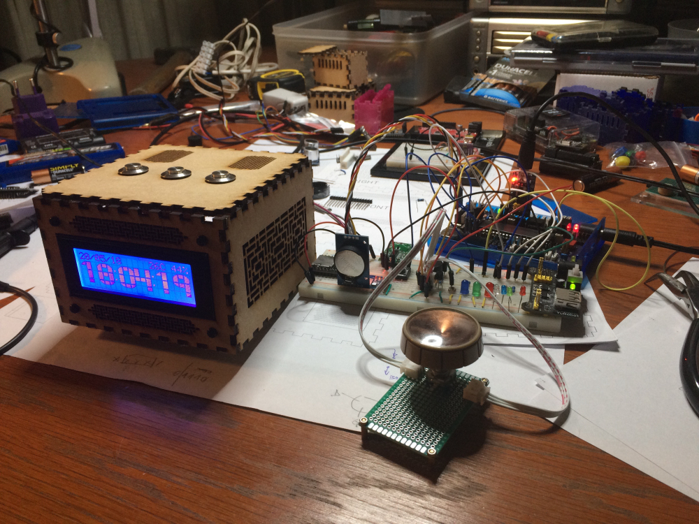
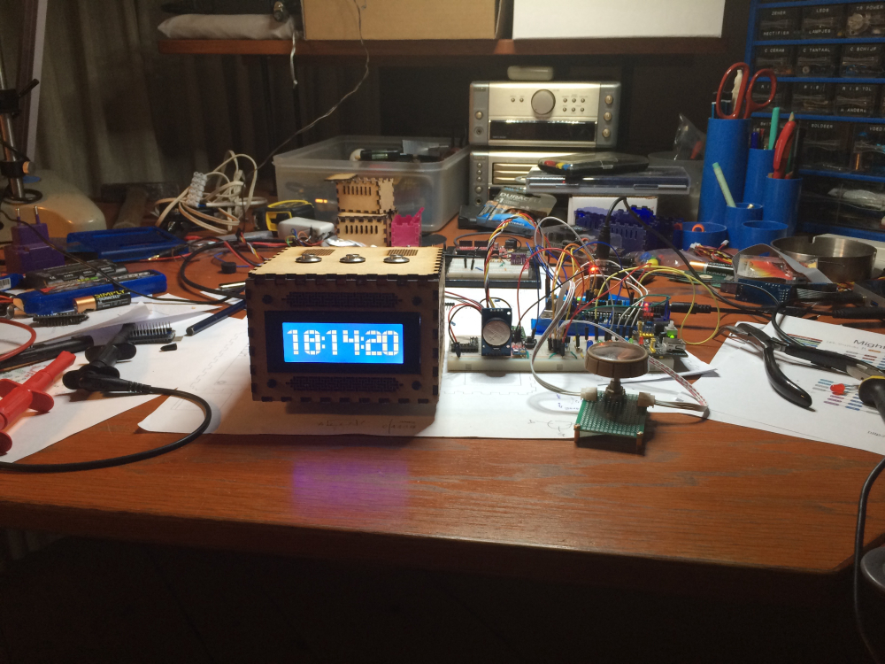
lasercut box
atmega1284p based
DS3231 rtc (very accurate and 2 alarms!)
LDR
20 by 4 LCD, two sizes of numbers, menu driven setup
buzzer
leds for moodlighting
doppler for proximity detection
encoder for scrolling through values (for setting time)
buttons with LED feedback for interactivity
mp3 player
most interface objects MySensorised :-)This entry is to boost my energy, because we are still a long way from home (pcb is still not made, focus is now on prototype and software).
-
Is there a way to check presence of a MySensors network, and proceed without if not found ?@mfalkvidd
Nope, I probably got this from a forum message somewhere. I’m not sure where I got the suggestion to use the define.
The thing is, it is very nice to have this #define, but as @Neverdie said, it would be nice to avoid that a node “hangs” if the gateway is unavailable. As far as I can see, there is no DEBUG message if the network is not reachable. And for a new MySensors user a hanging node is really confusing (it is sometimes for me as well). So this #define will now be part of me ‘default’ template until the standard behaviour is adapted. -
Is there a way to check presence of a MySensors network, and proceed without if not found ?@mfalkvidd from an example where it mentioned
#define MY_TRANSPORT_WAIT_READY_MS 5000I would expect this to be the default, and not '0'
-
Is there a way to check presence of a MySensors network, and proceed without if not found ?I'm not sure if the current default behaviour of MySensors is to wait for 5 seconds before giving up and moving on. I was under the impression that a node would try to find a network until my hair grows back.
When the define is included in the sketch, it clearly does it's job.
@NeverDie probably meant that we should not need to set the define, unless we want to change the default 5sec wait time, or if we explicitly want to have the node hang until a network is found.
So the question is, is the default behaviour to keep looking for a network, or does the library stop after 5sec and move on with the setup() ?
-
💬 Raspberry Pi gateway interface@pihome I have now used it first as a serial gateway. Now I'm using it as a ethernet gateway (since Raspberry gateway code is now included in MySensors build).
-
[SOLVED] Anyone a working example of the combination NewPing 1.9 and MySensors 2.2.0 ?@gertsanders [SOLVED]: a wrong type in a declaration gave constant '0' values. Now corrected and distances is now measured correctly.
-
[SOLVED] Anyone a working example of the combination NewPing 1.9 and MySensors 2.2.0 ?Does anyone have a working example of the combination NewPing 1.9 and MySensors 2.2.0 ?
I keep getting distance = 0, while the basic distance sensor sketch works perfectly (on the same setup), so the hardware side is OK.