Navigation

    • Register
    • Login
    • OpenHardware.io
    • Categories
    • Recent
    • Tags
    • Popular
    1. Home
    2. GertSanders
    3. Best
    • Profile
    • Following
    • Followers
    • Topics
    • Posts
    • Best
    • Groups

    Best posts made by GertSanders

    • My basement flooding alarm

      My basement flooding alarm was put in place because this year we have seen extreme rain on a few occasions, which in one case actually flooded the street, and as a result also my basement.

      With the electrical cabinet and utility connections in the basement, that could have been very bad, if waterlevels had reached the cabinet itself, so I needed a way to measure waterlevels and have an automatic start of a sump pump when not at home (now my neighbours called me at work to tell me what was happening in the street).

      As the house this alarm was built for, is not always occupied, we needed notifications via internet.

      In the house I set up a MySensors network with a few nodes and a Raspberry which integrates the Controller (Domoticz) and Gateway functions (nrf24l01+ directly connected via interface board to raspi).

      The basement is now being watched by a node which measures the distance to the floor using a cheap ultrasonic sensor. It will switch a relay if the "floor" rises a certain amount (10cm) and will switch off the relay when the "floor" is back within 2 cm from initial position.

      The node resets itself to a start position on startup. This means that during startup a first distance measurement is done. This is the "zero" level. Any deviation from that first measured distance is "the change".

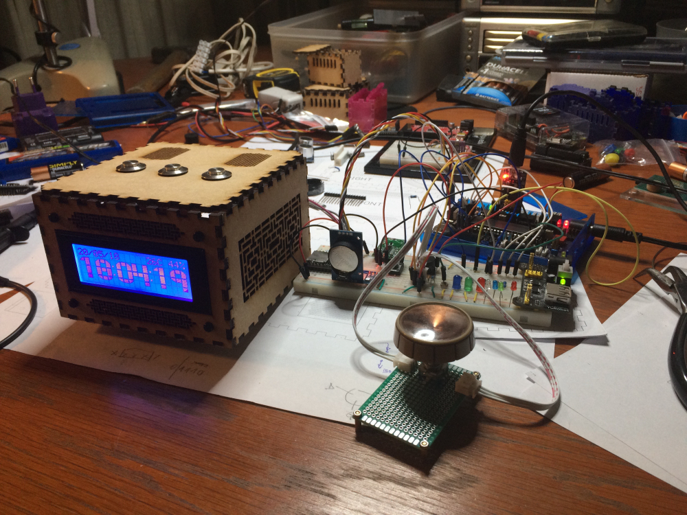
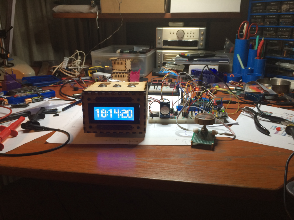
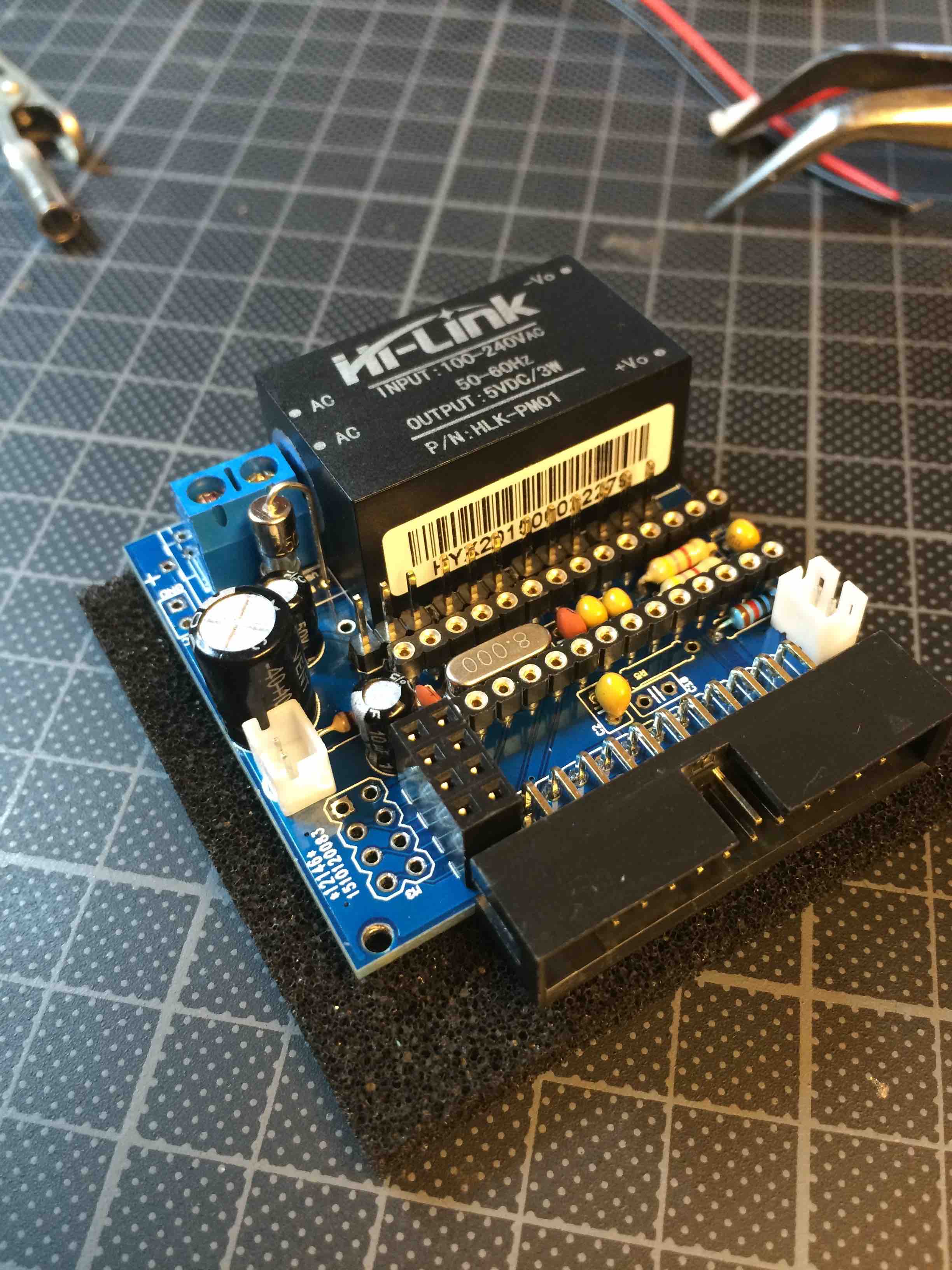
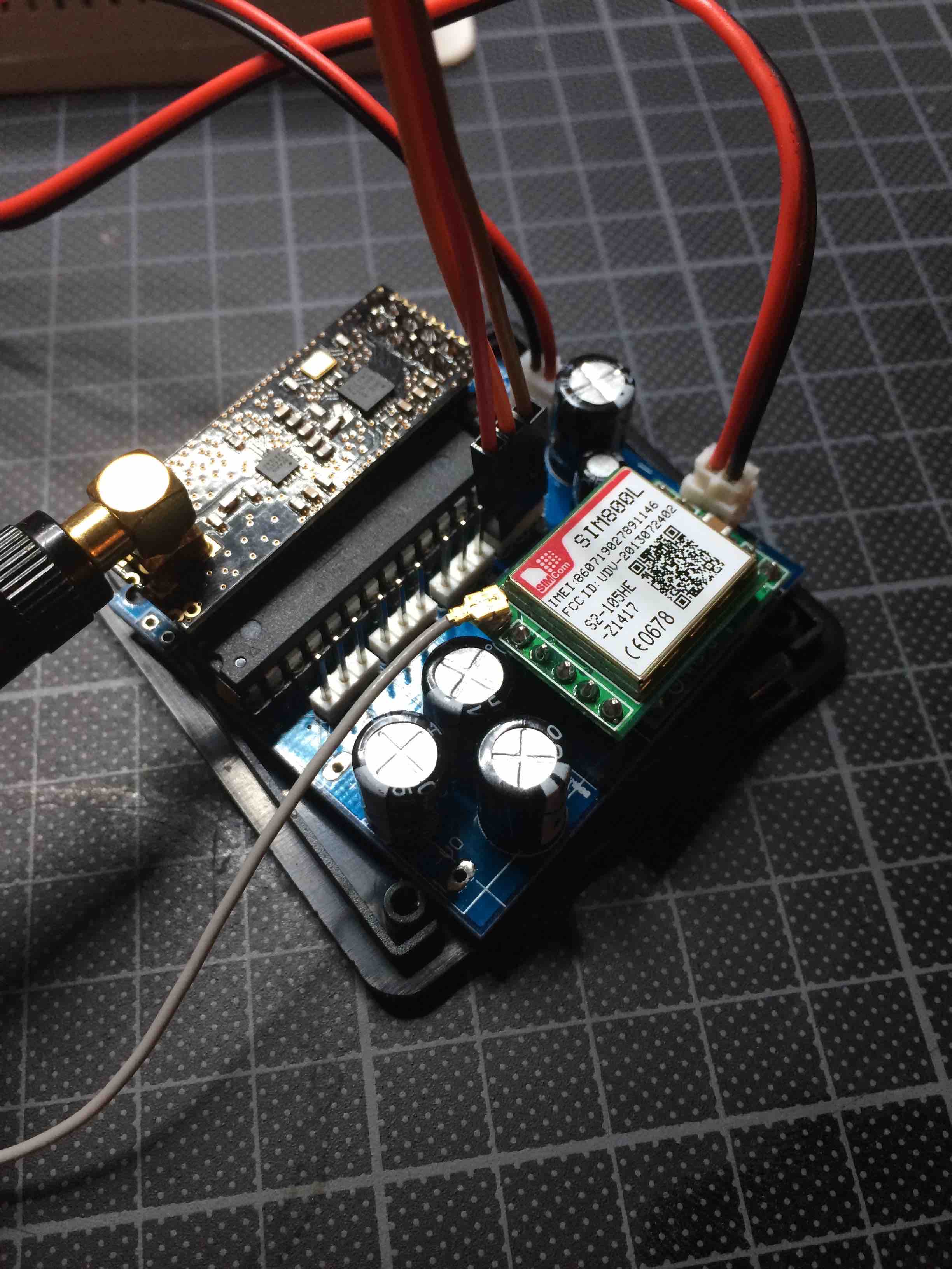
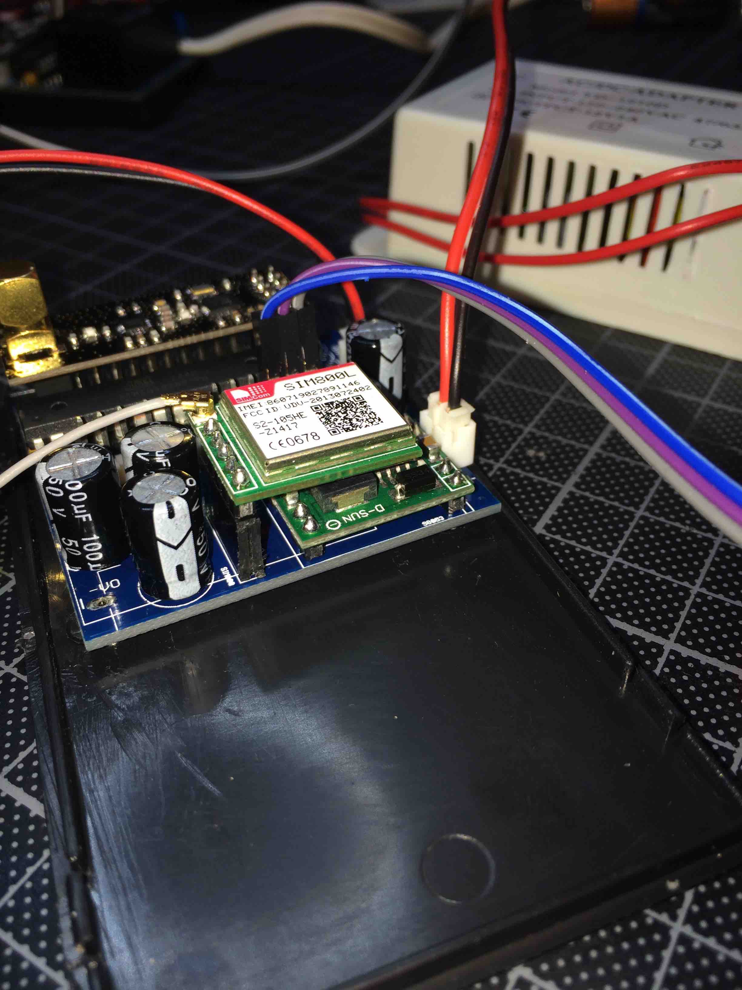
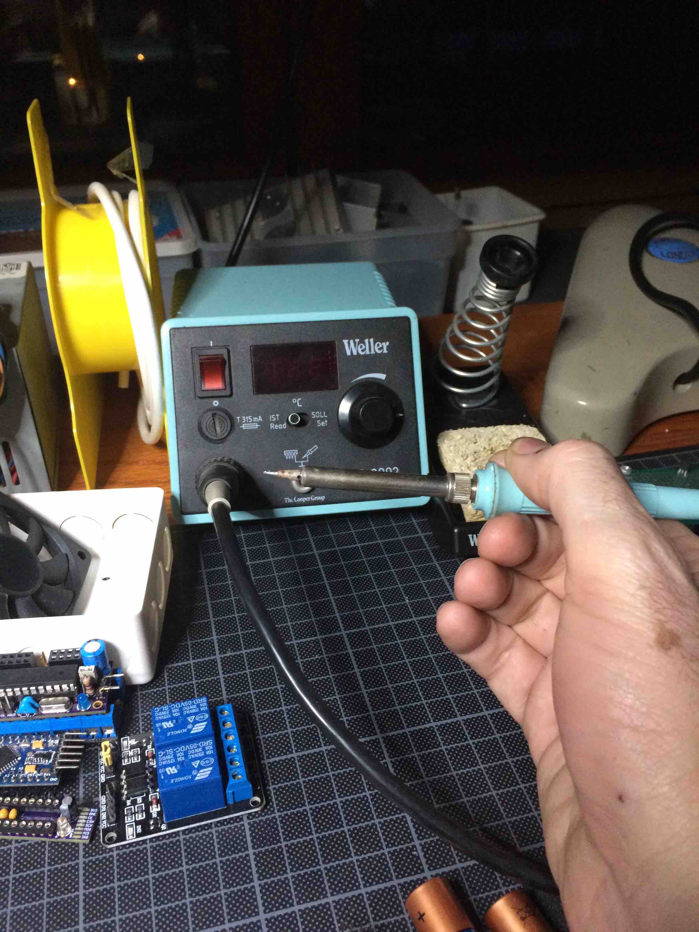
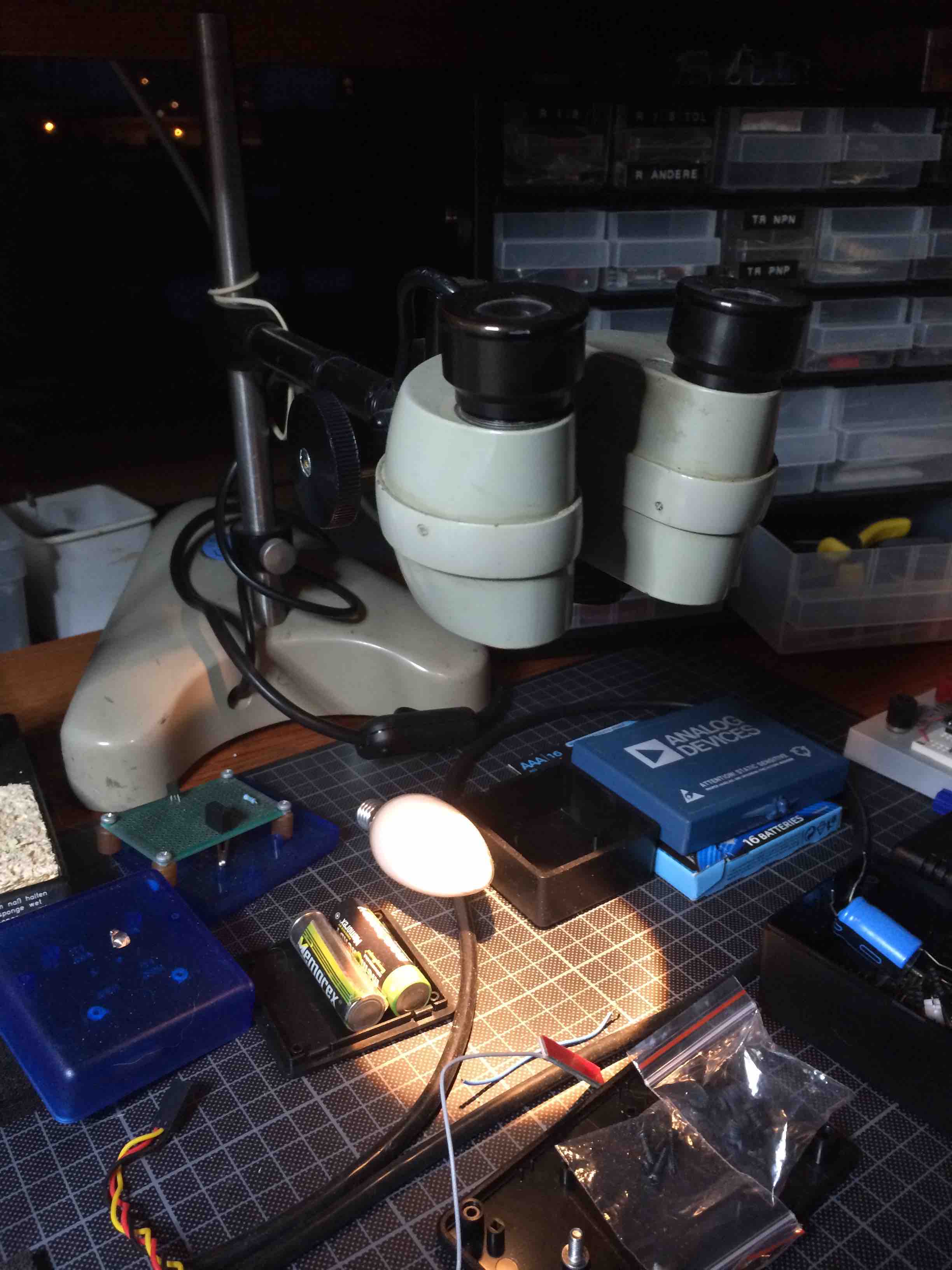
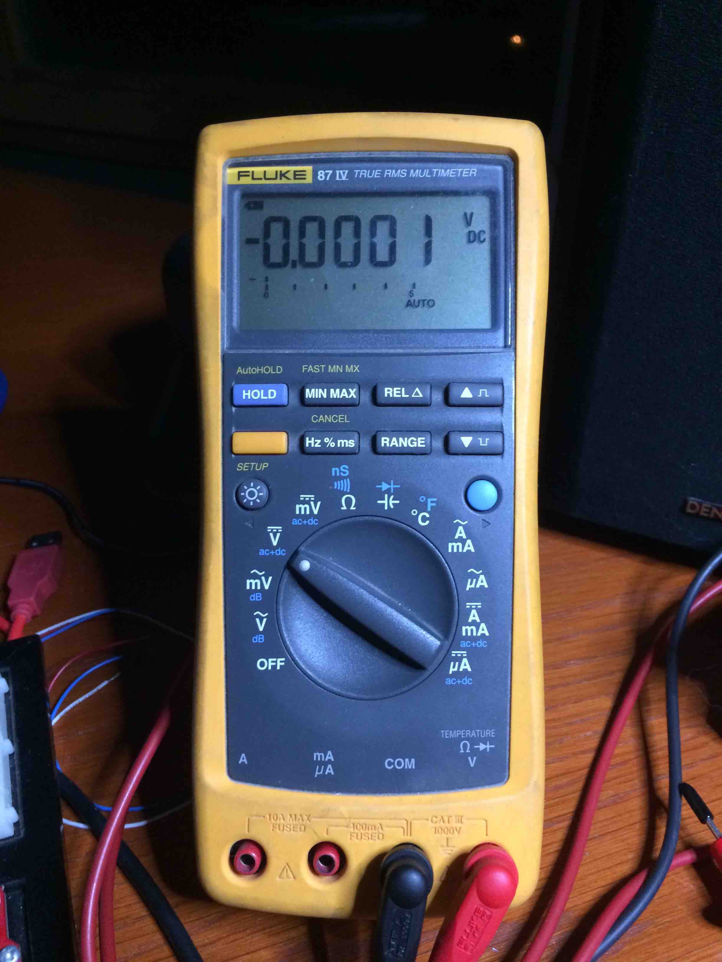
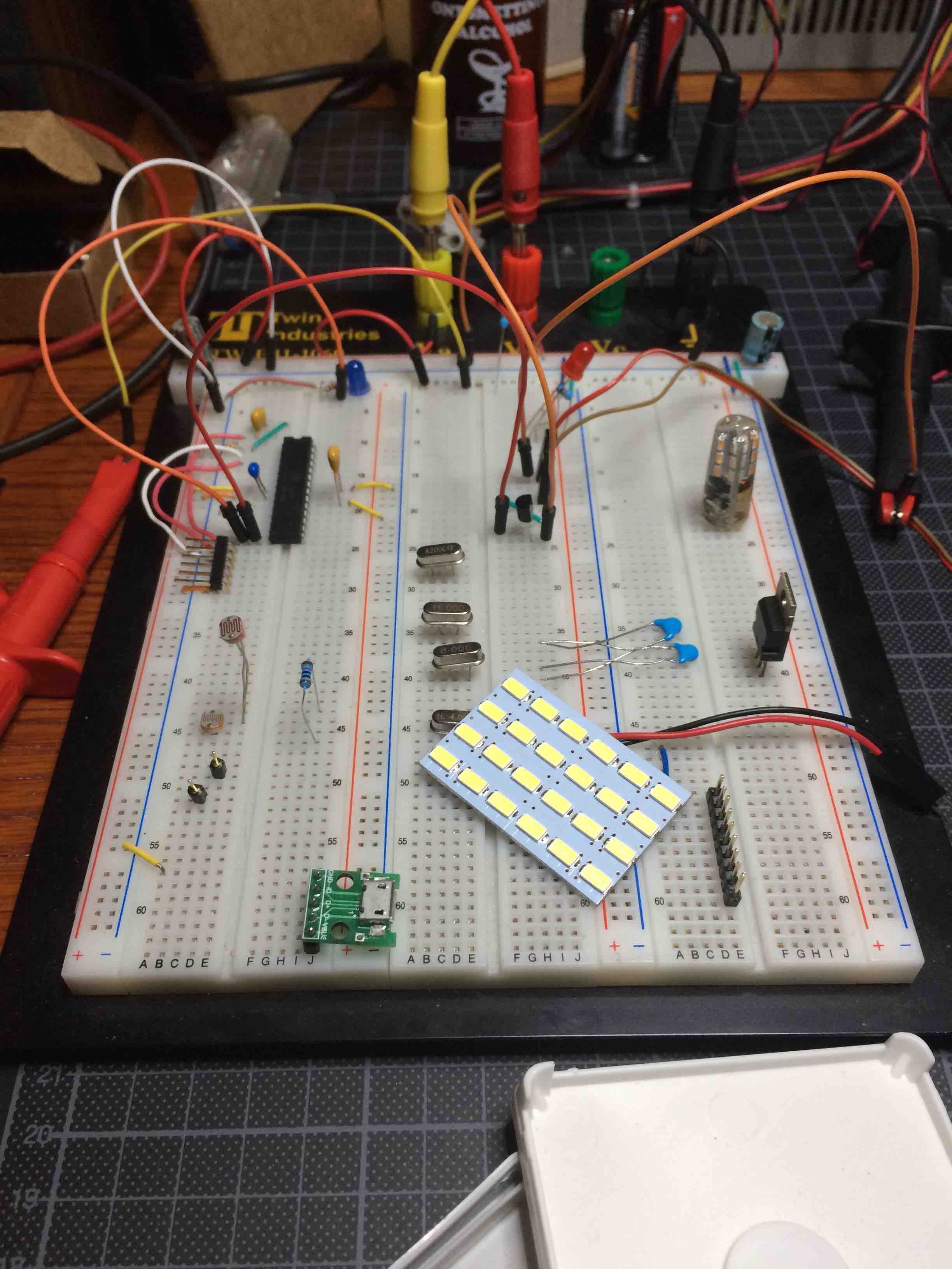
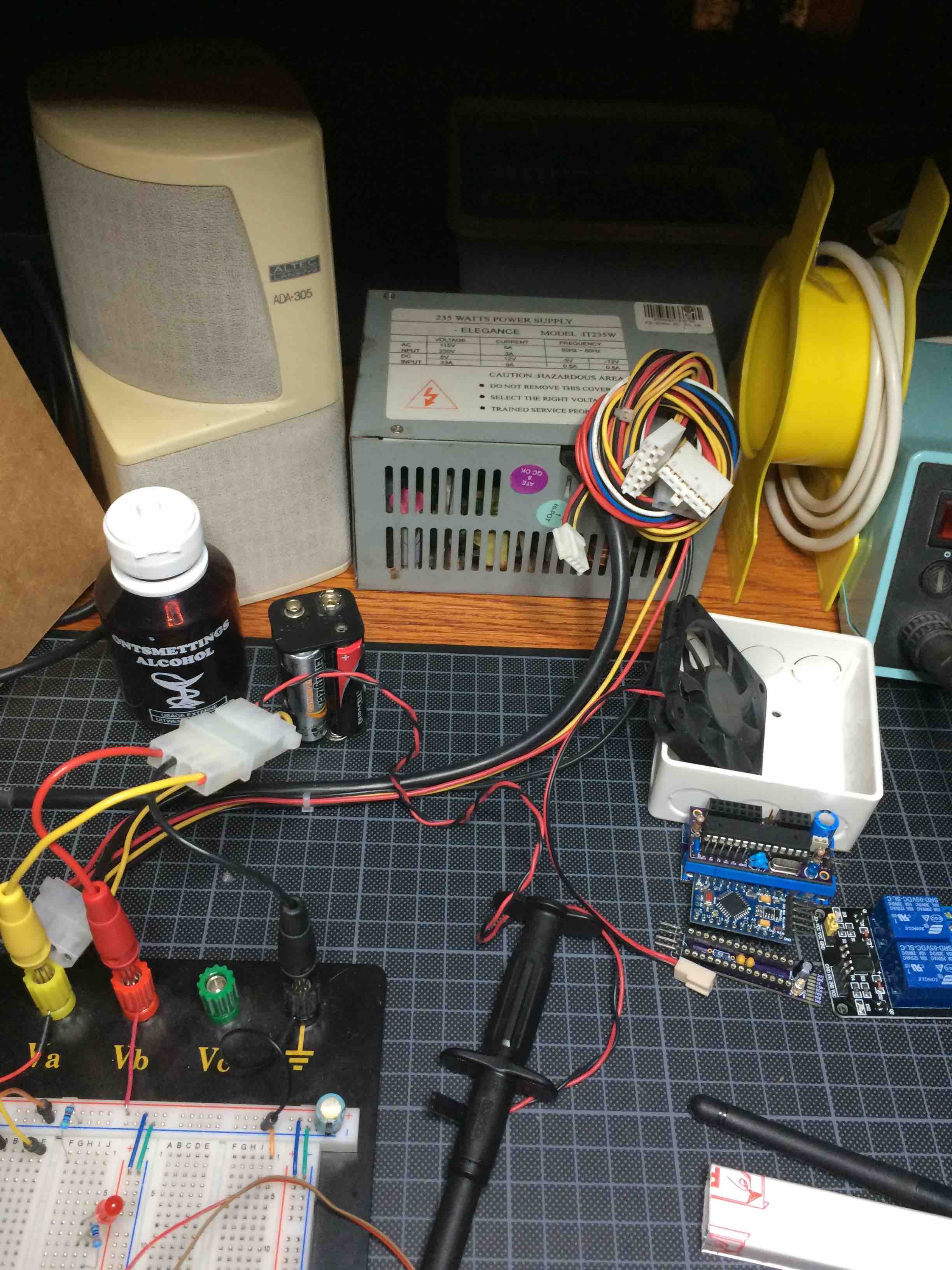
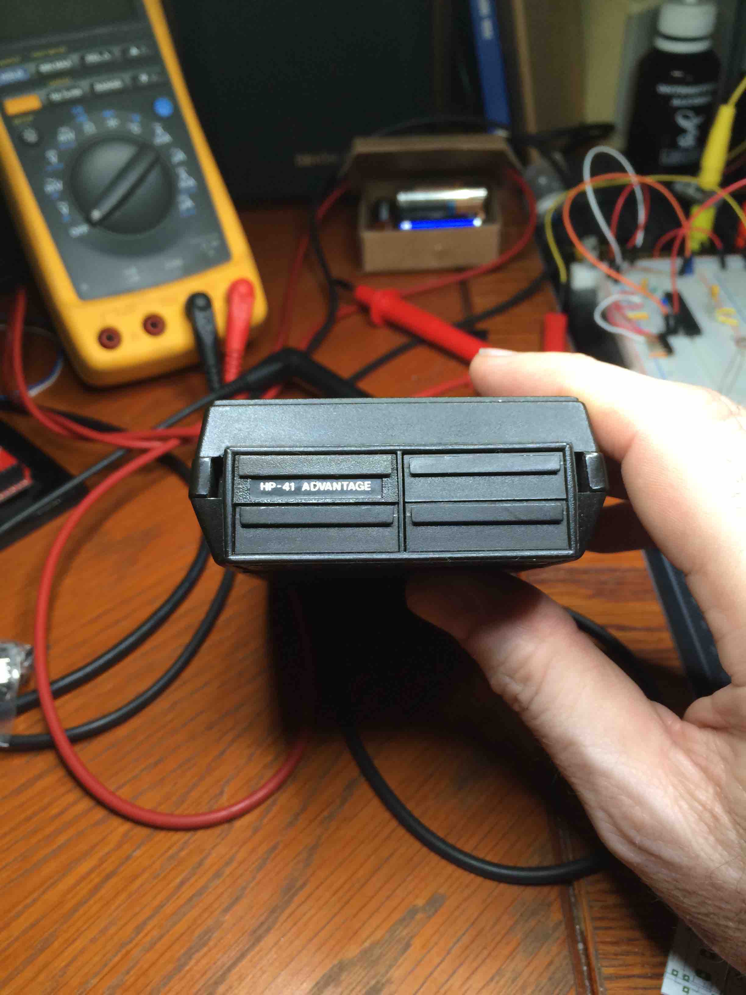
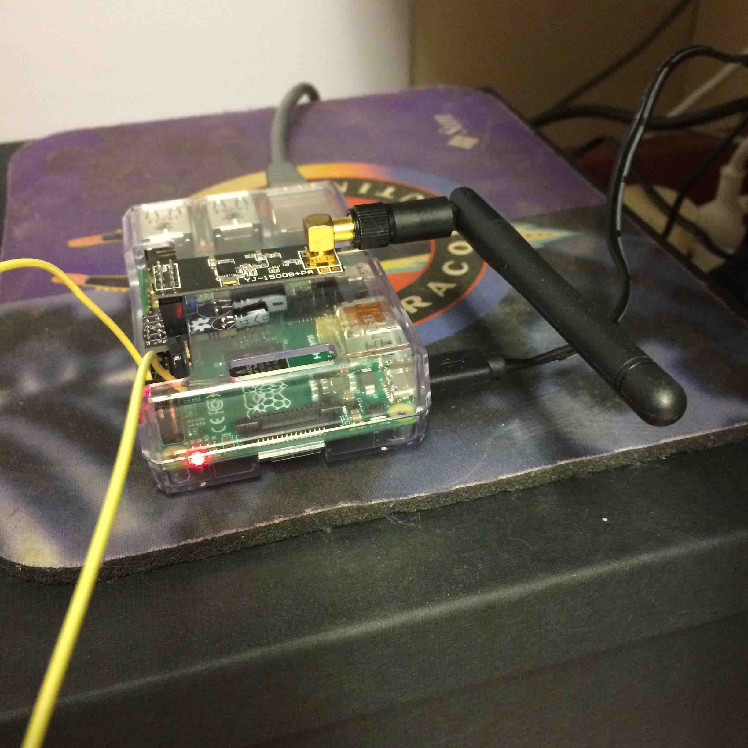
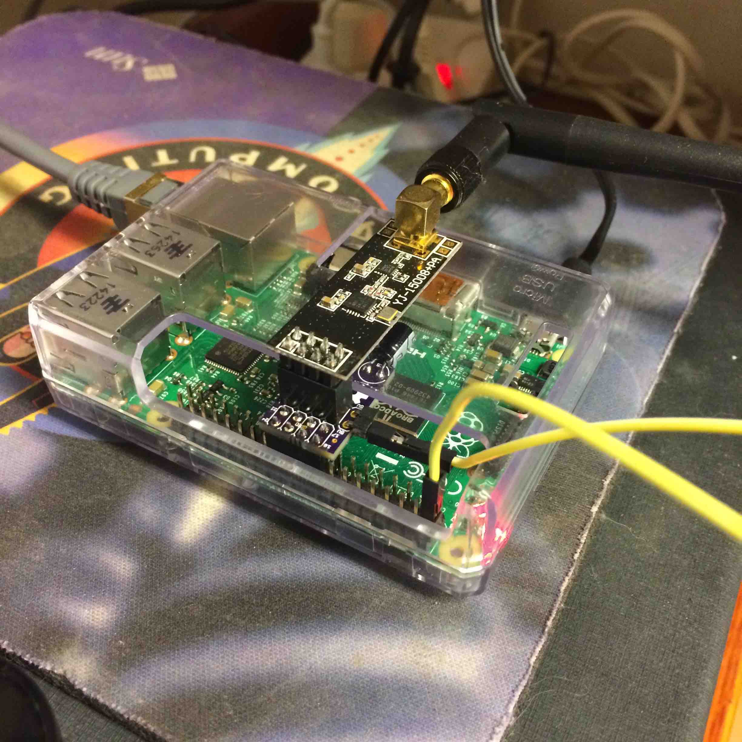
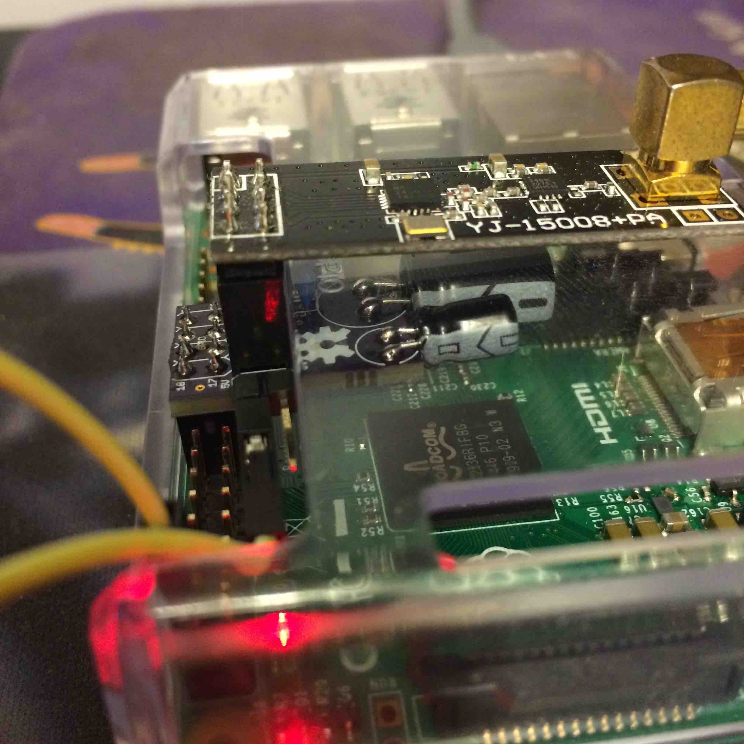
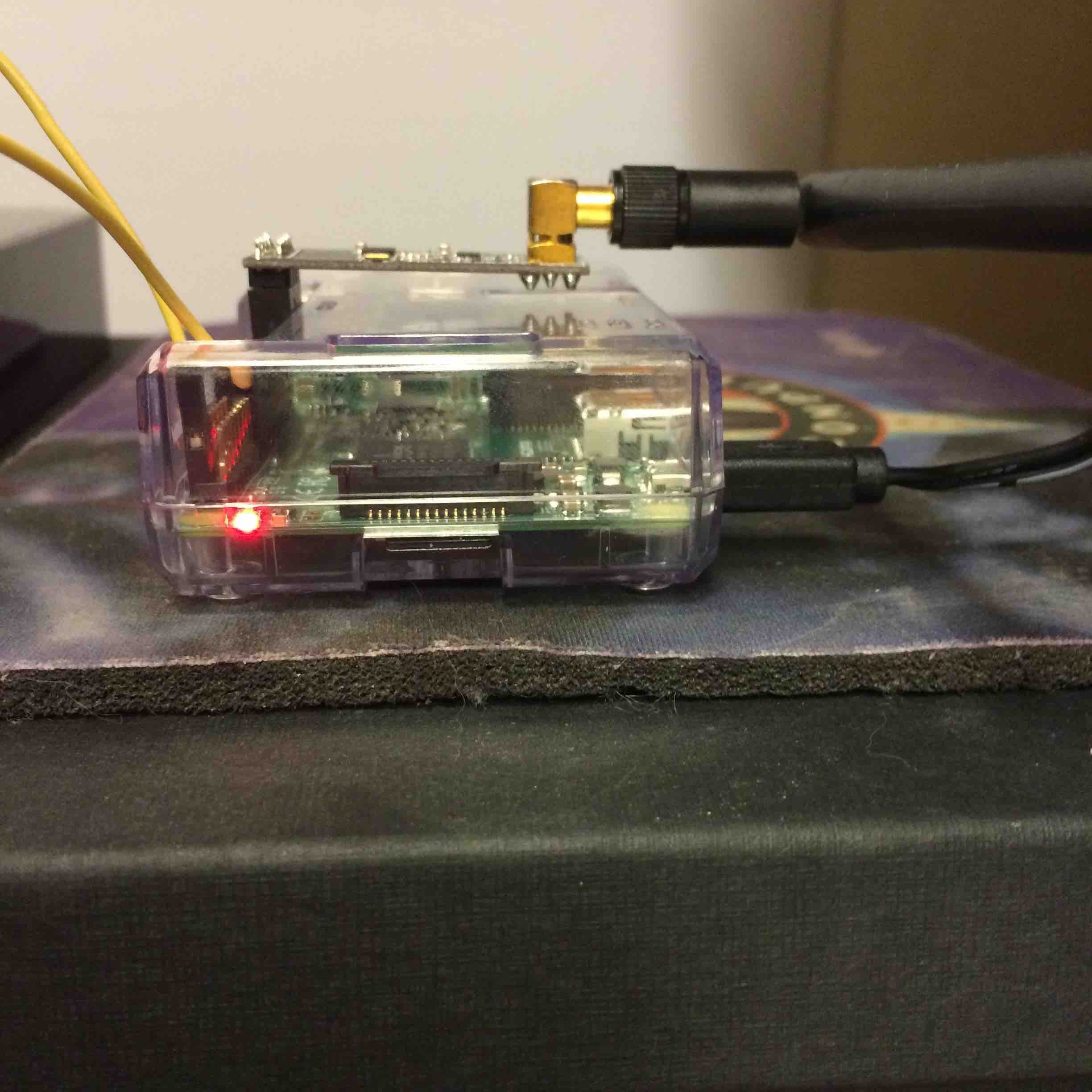
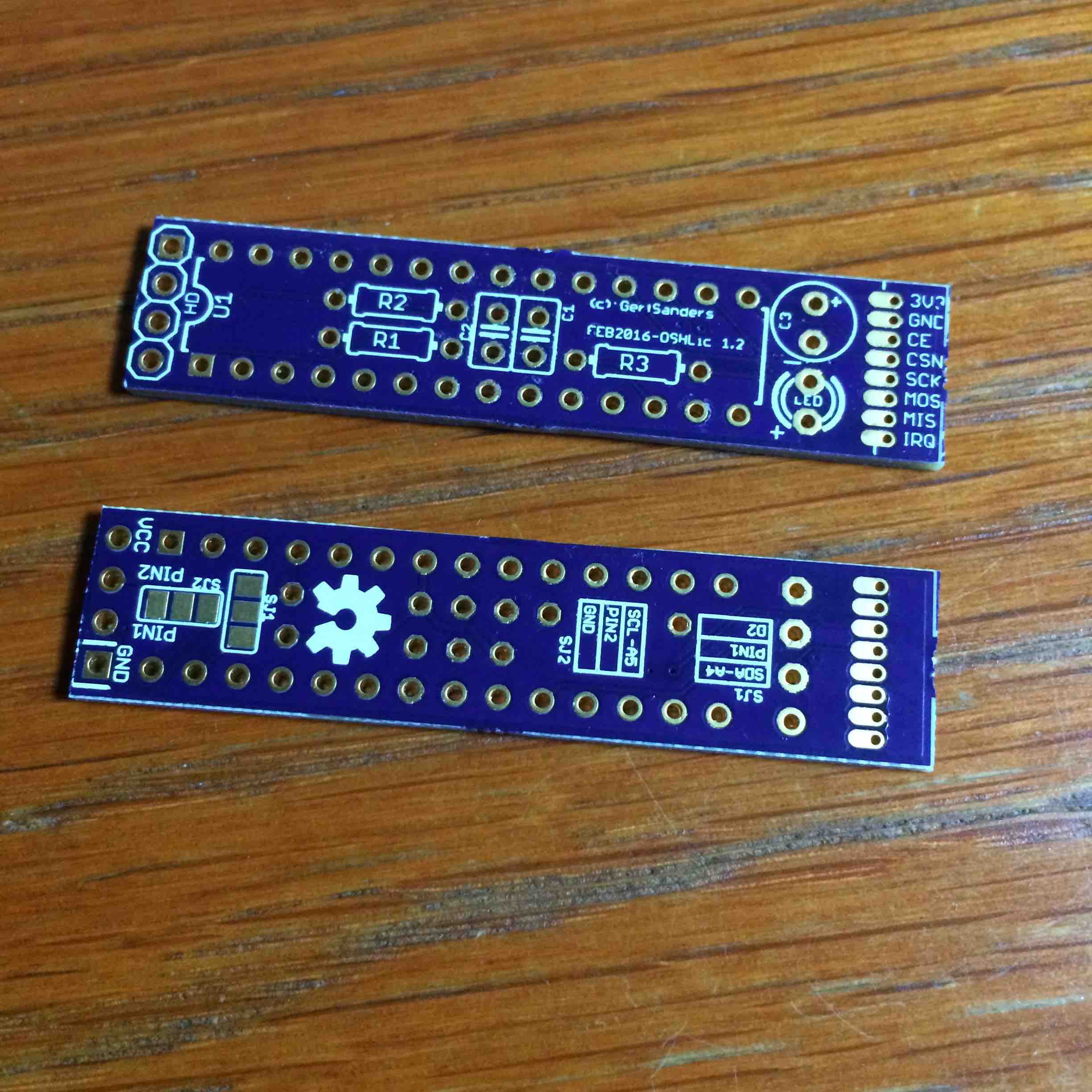
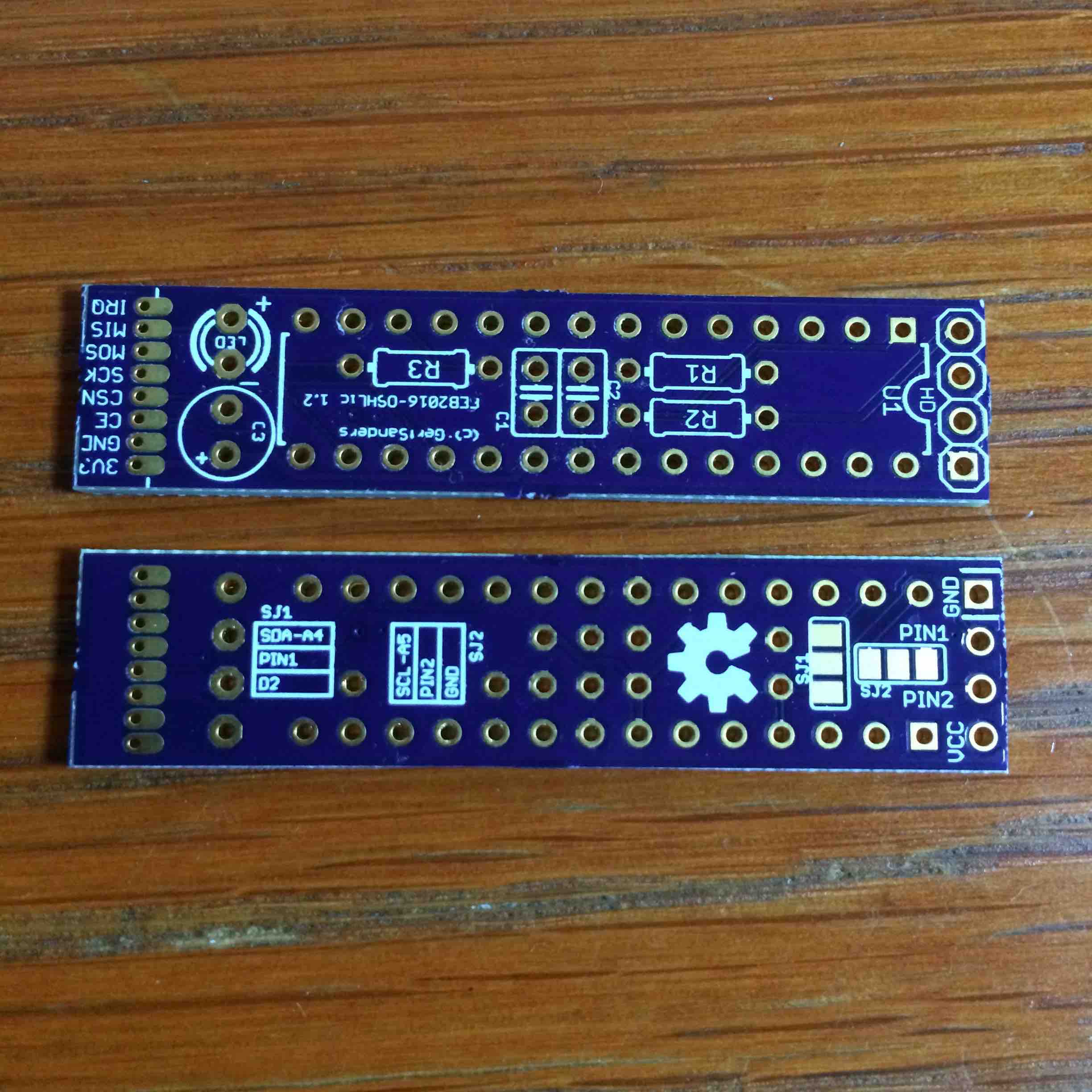
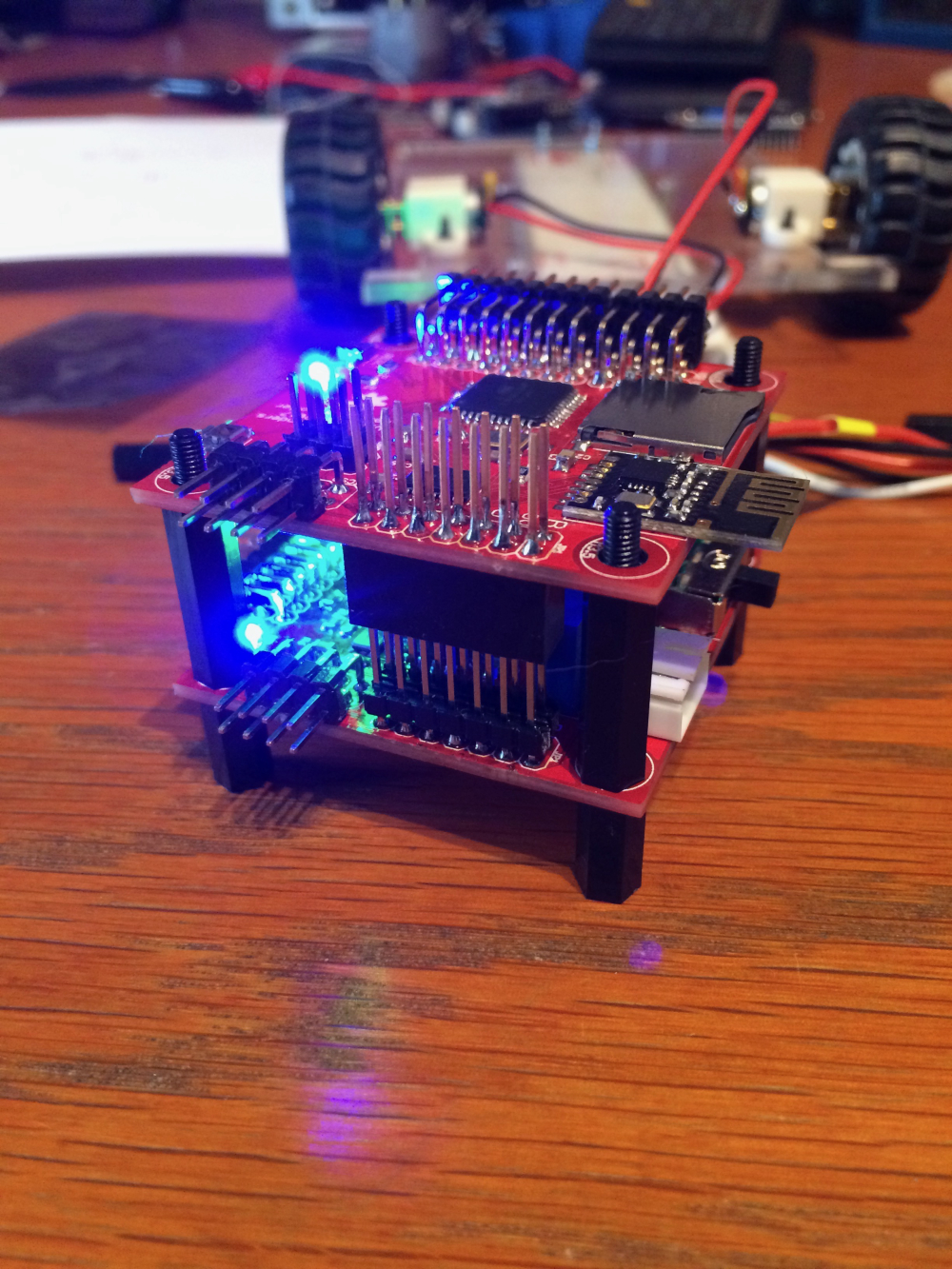
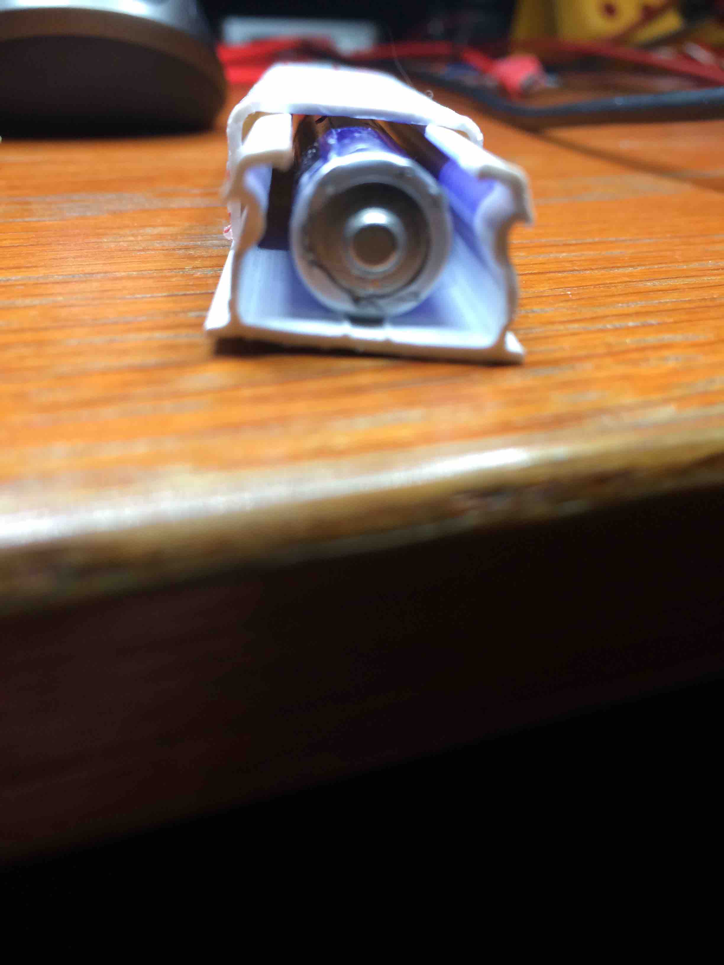
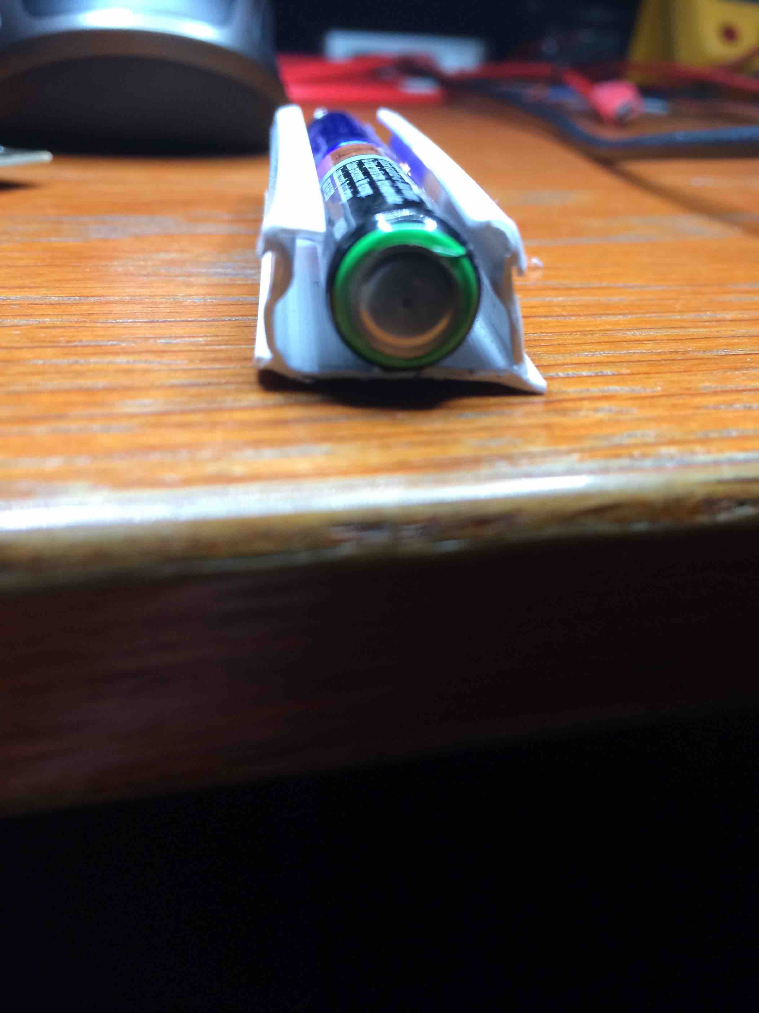
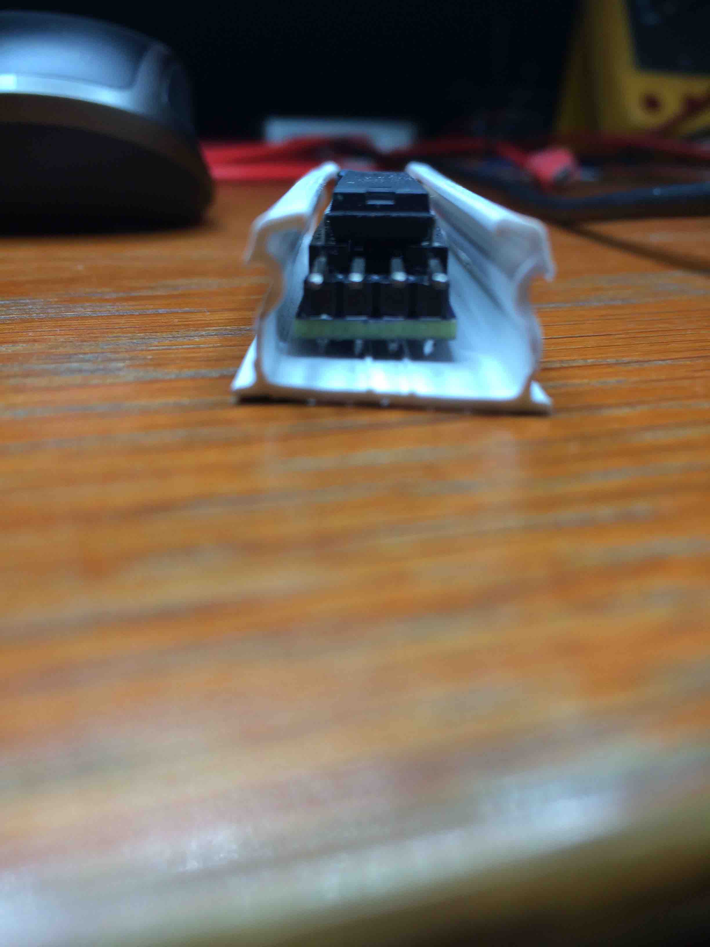
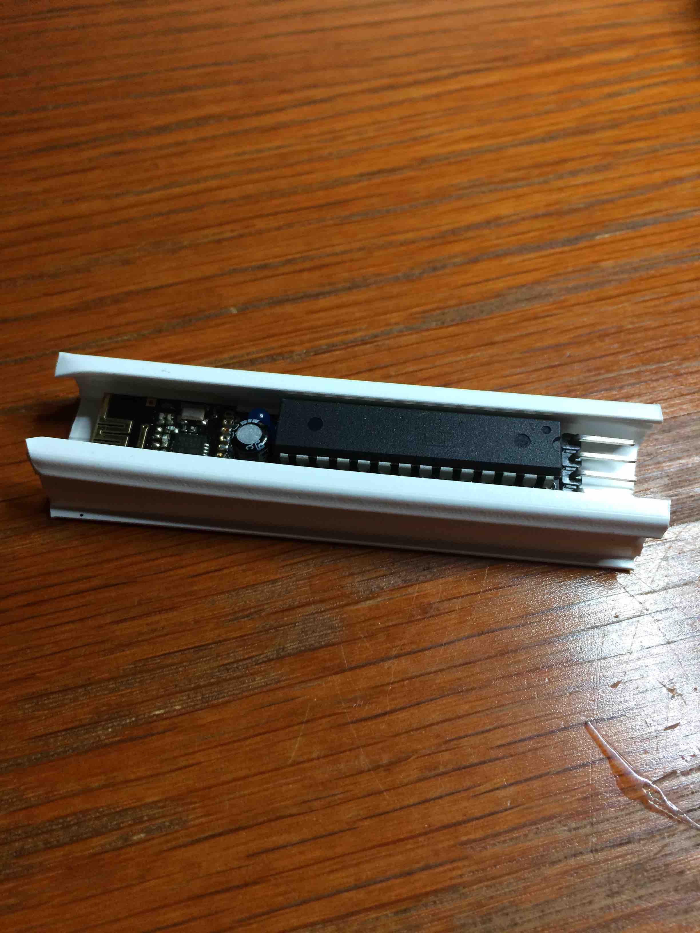
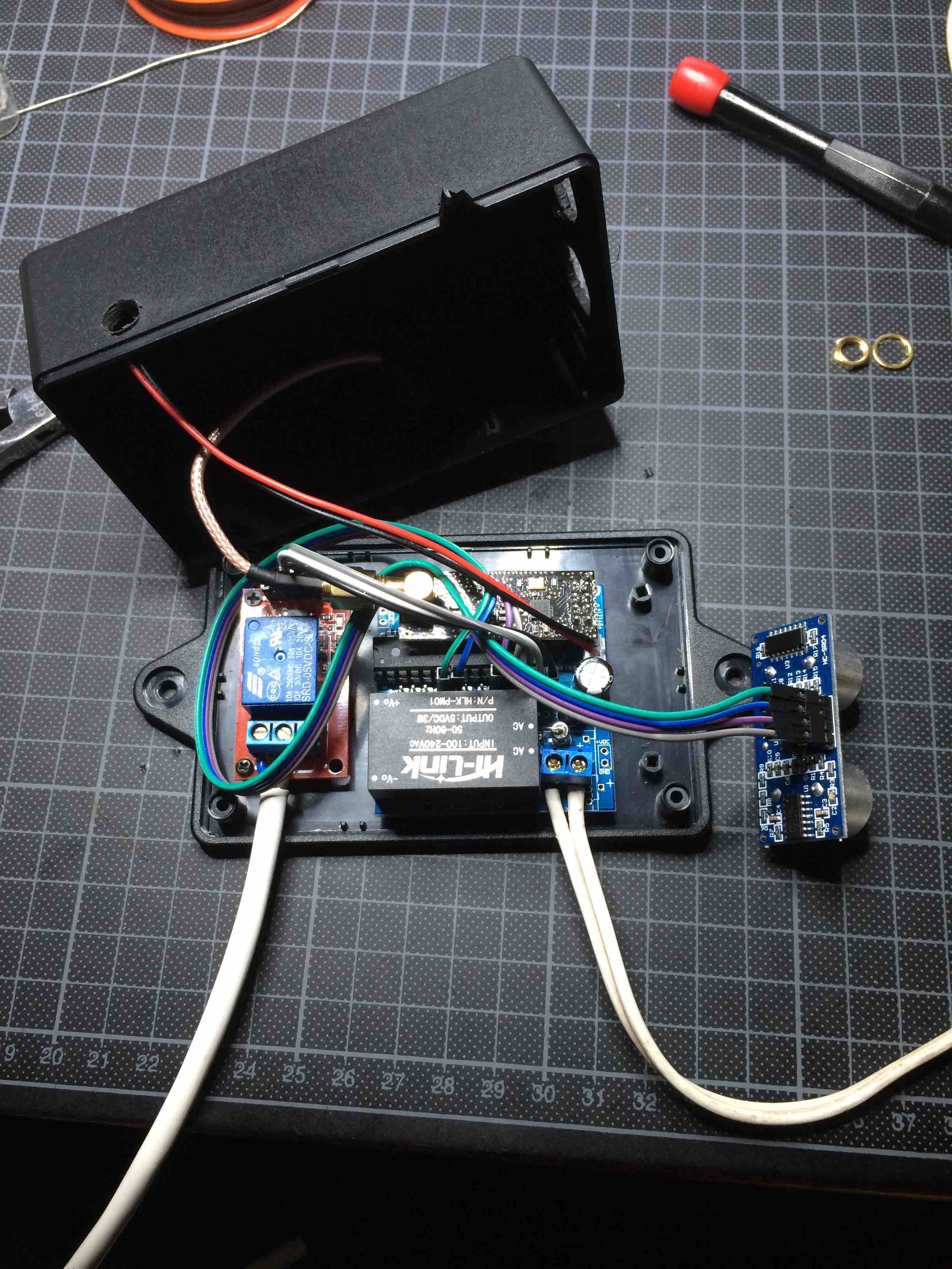
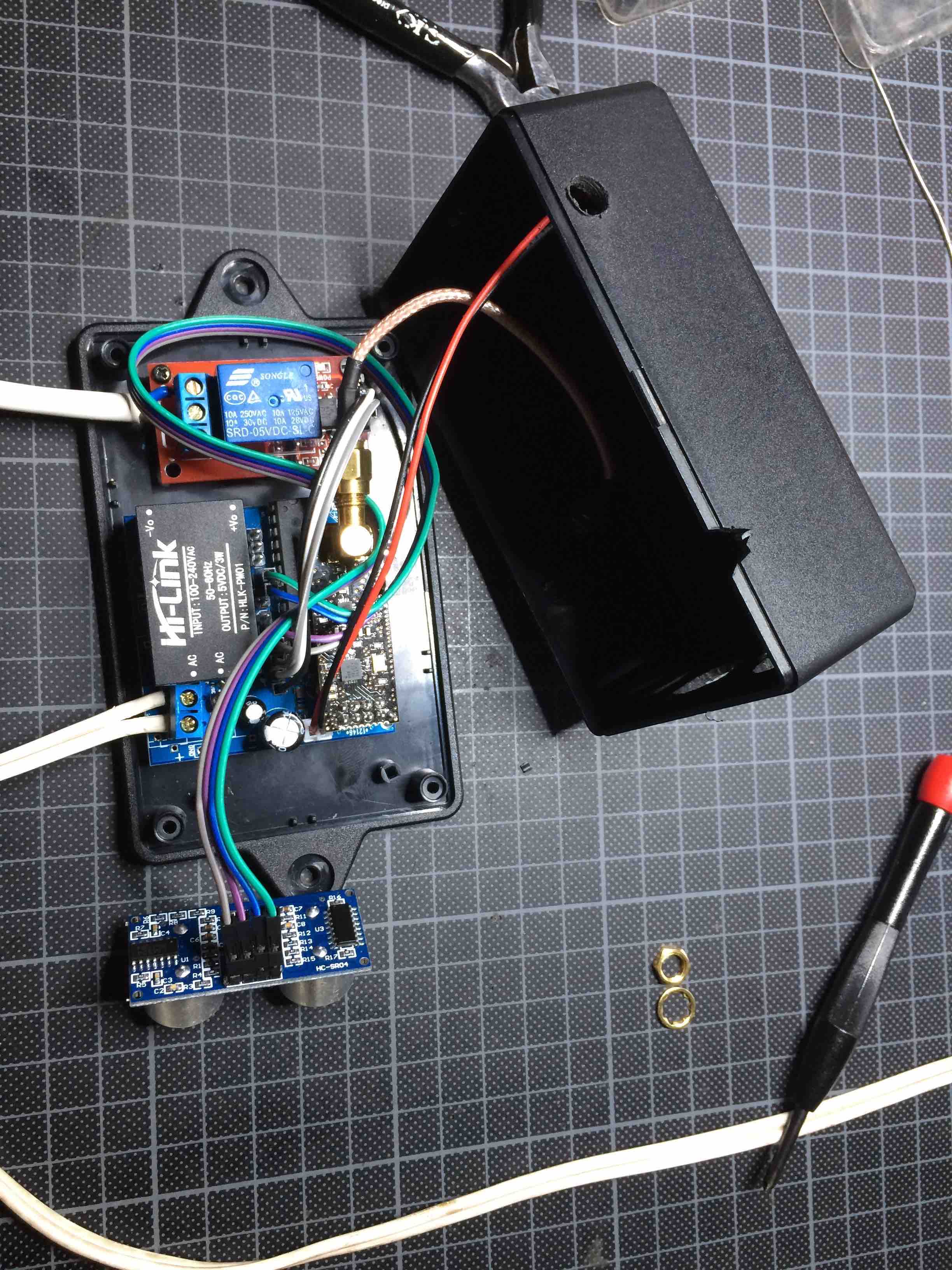
      Here are some pictures of the node while not yet in the box:

      0_1472291244262_IMG_8025.jpg
      0_1472291266312_IMG_8026.jpg

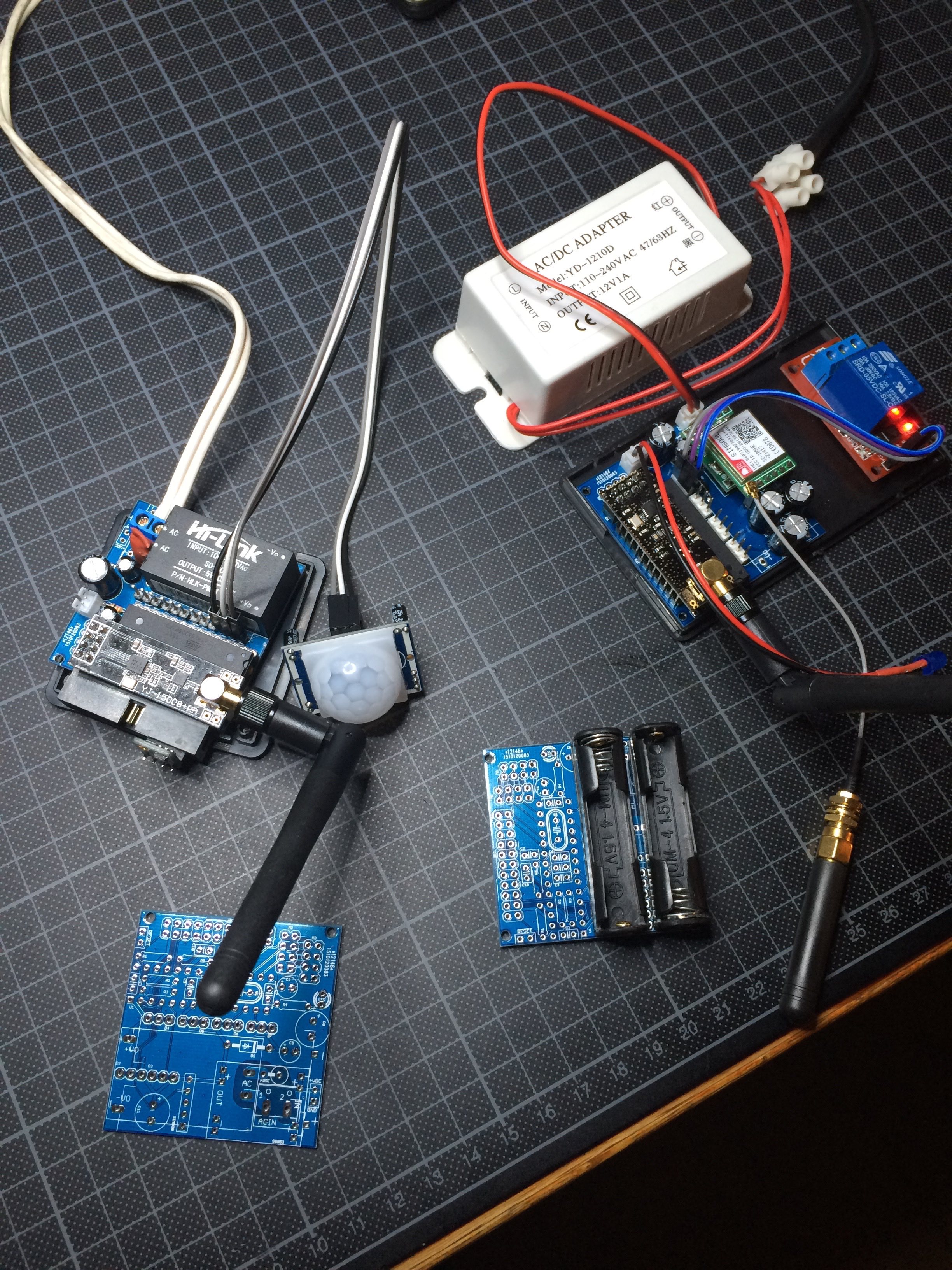
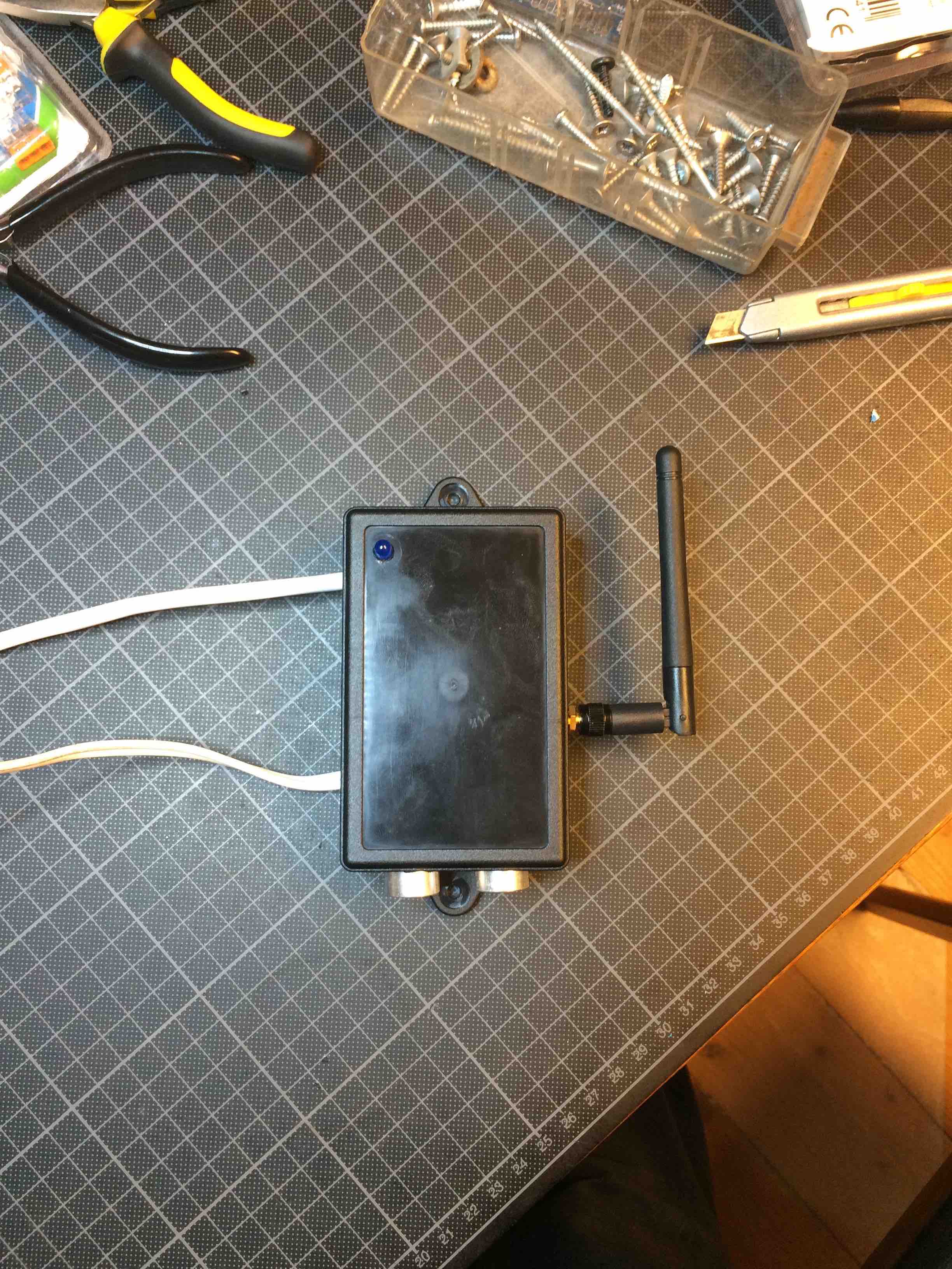
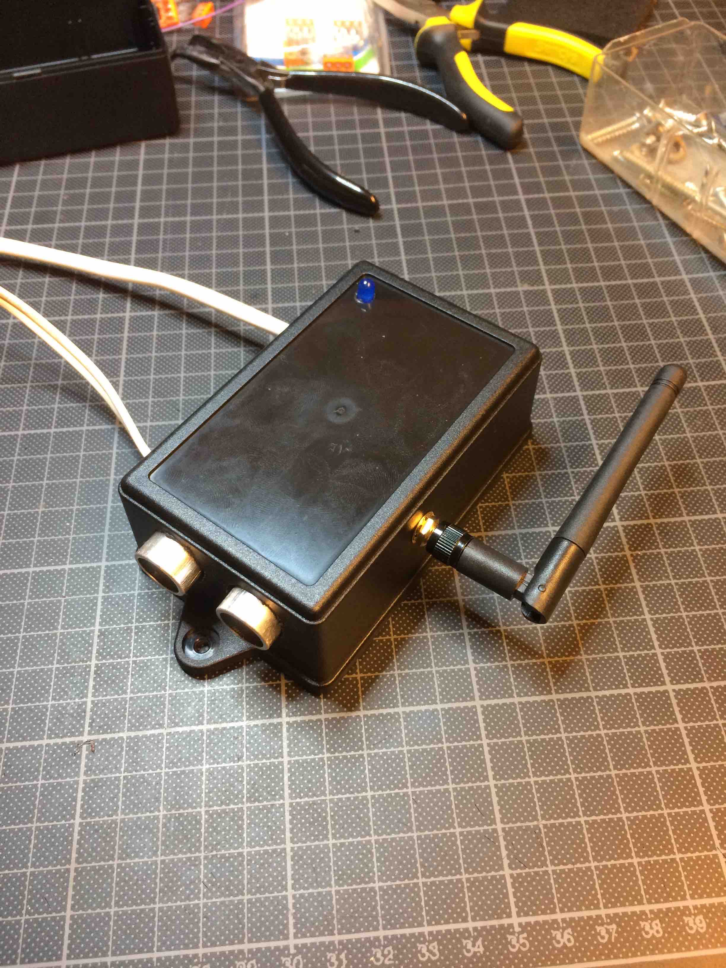
      And when mounted in the box:

      0_1472291297936_IMG_8029.jpg
      0_1472291314553_IMG_8028.jpg

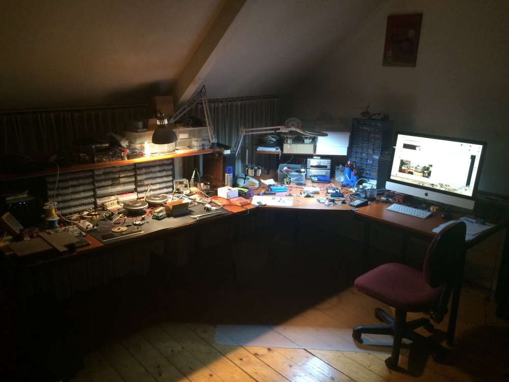
      I then installed this in the basement next to the electrical cabinet:

      0_1472291343668_IMG_8037.jpg

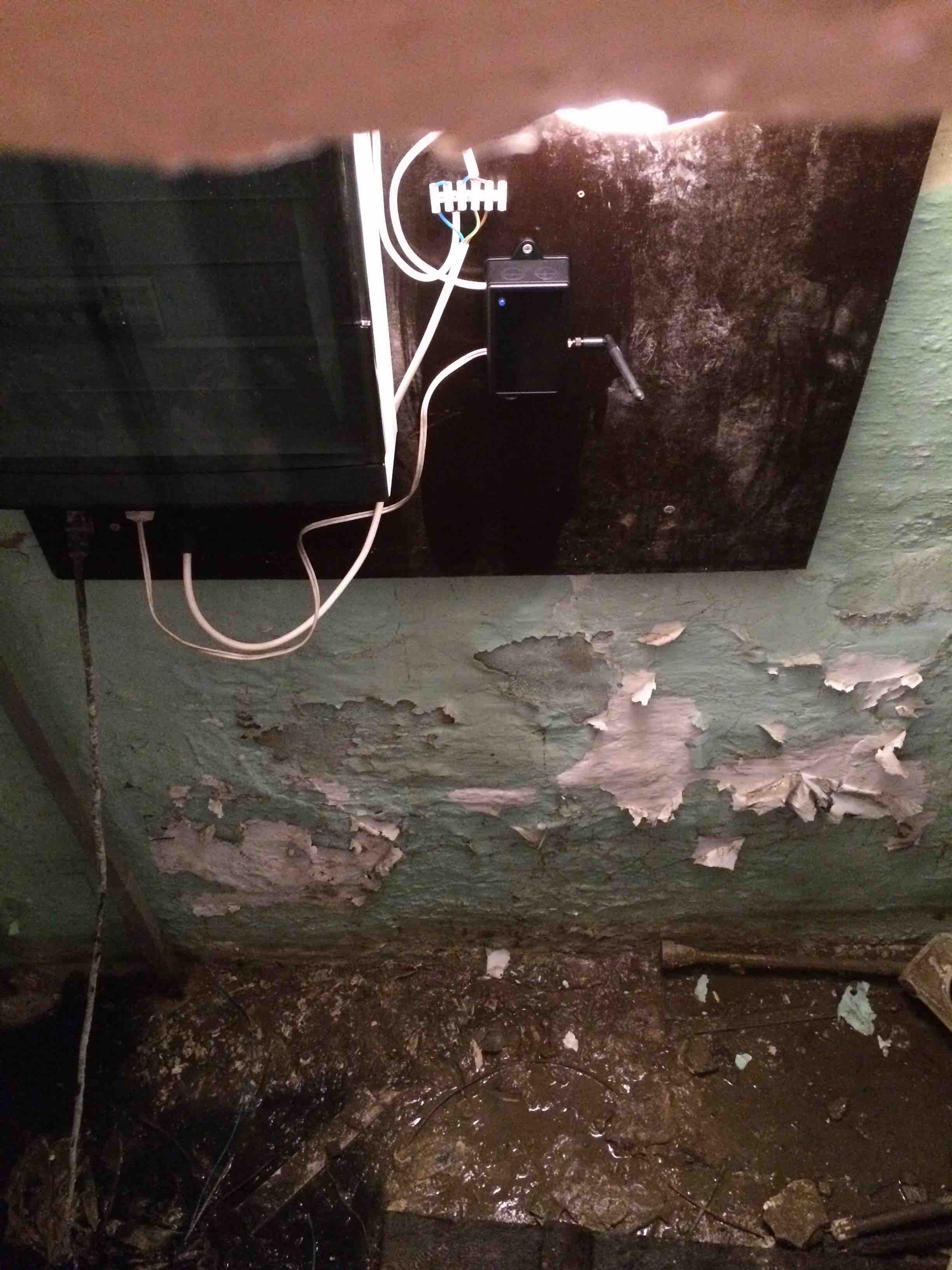
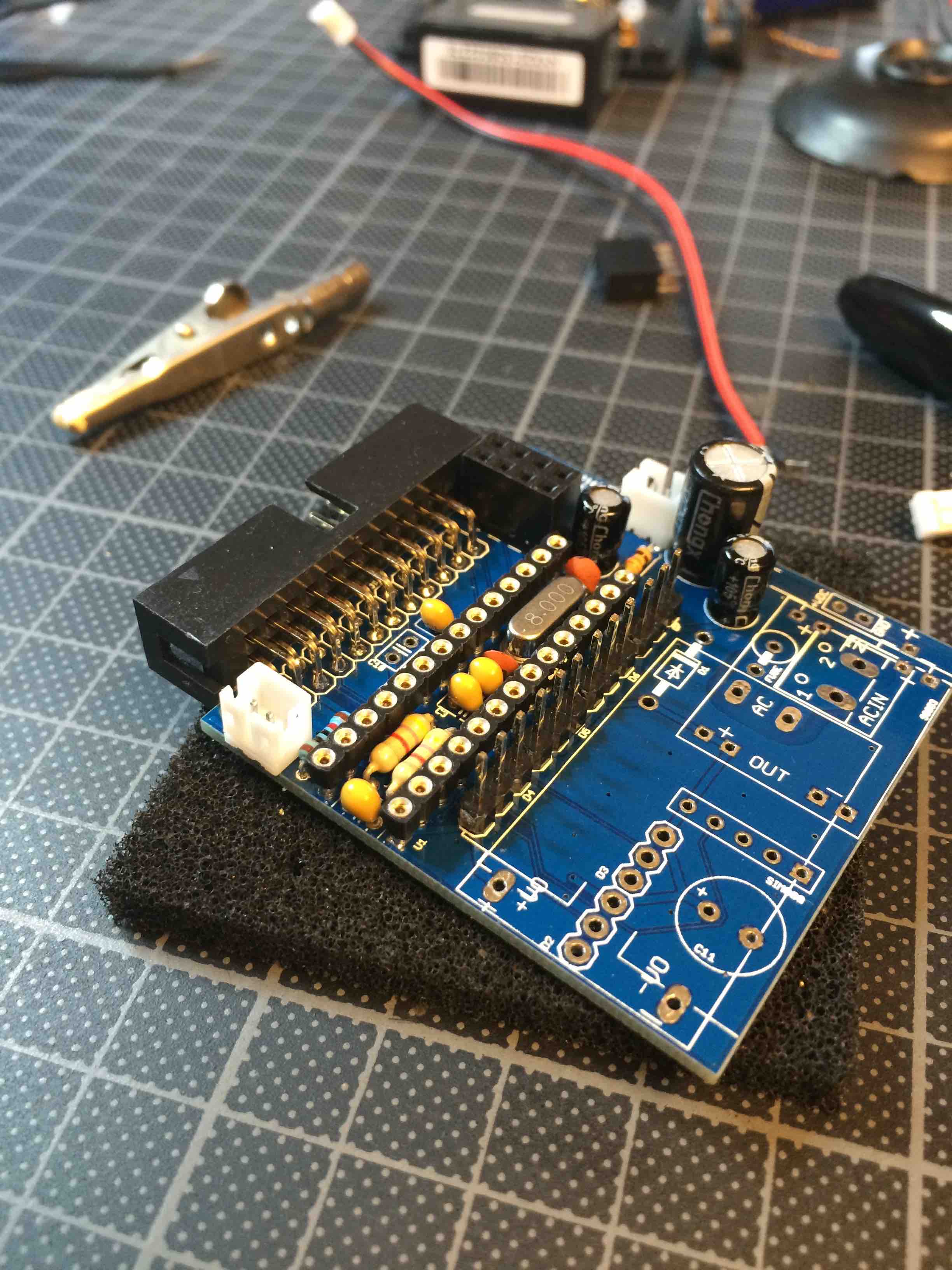
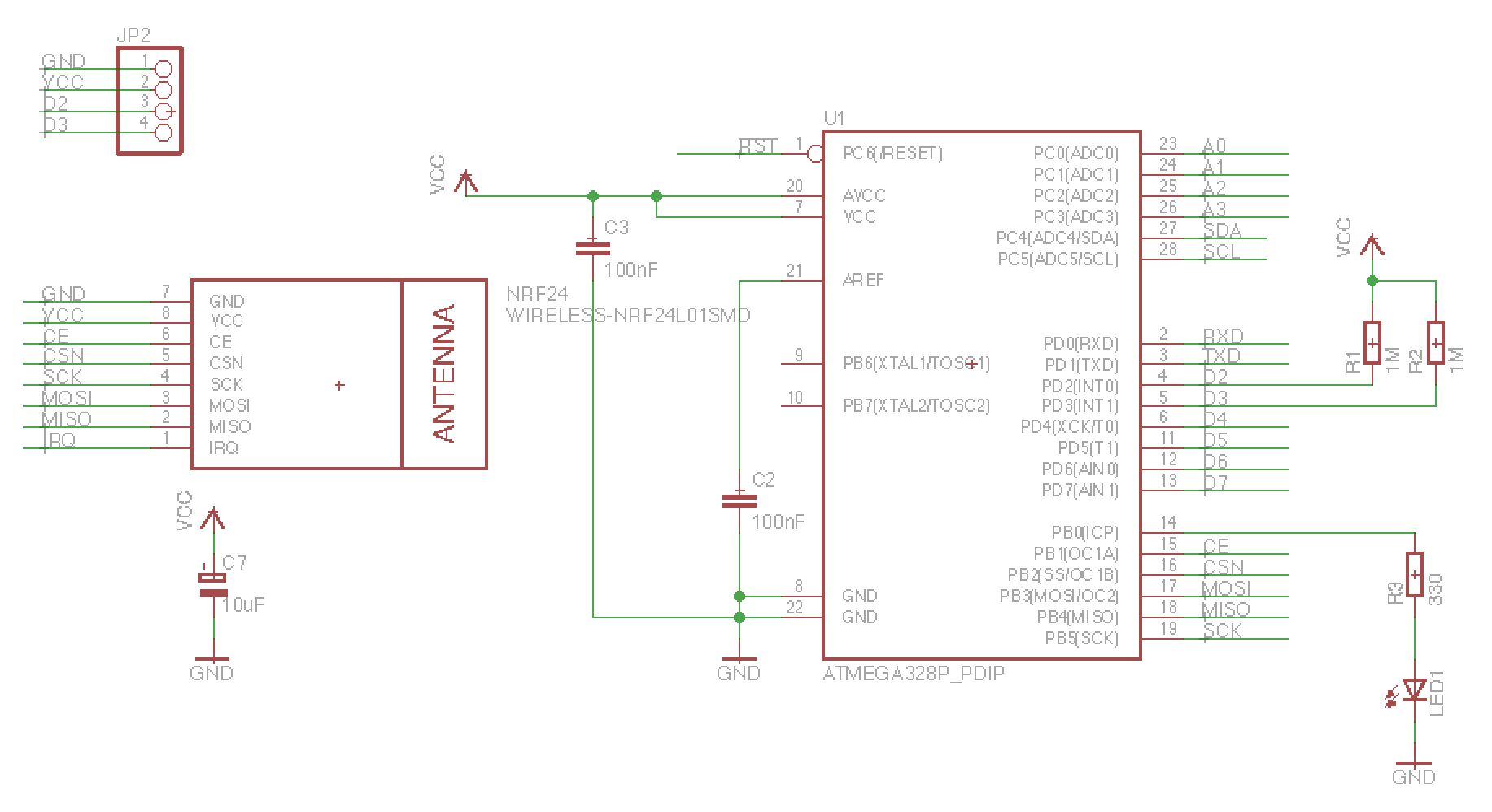
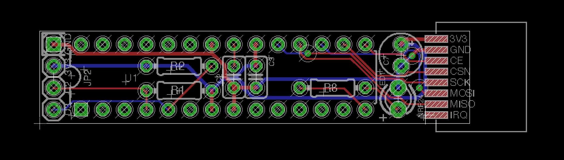
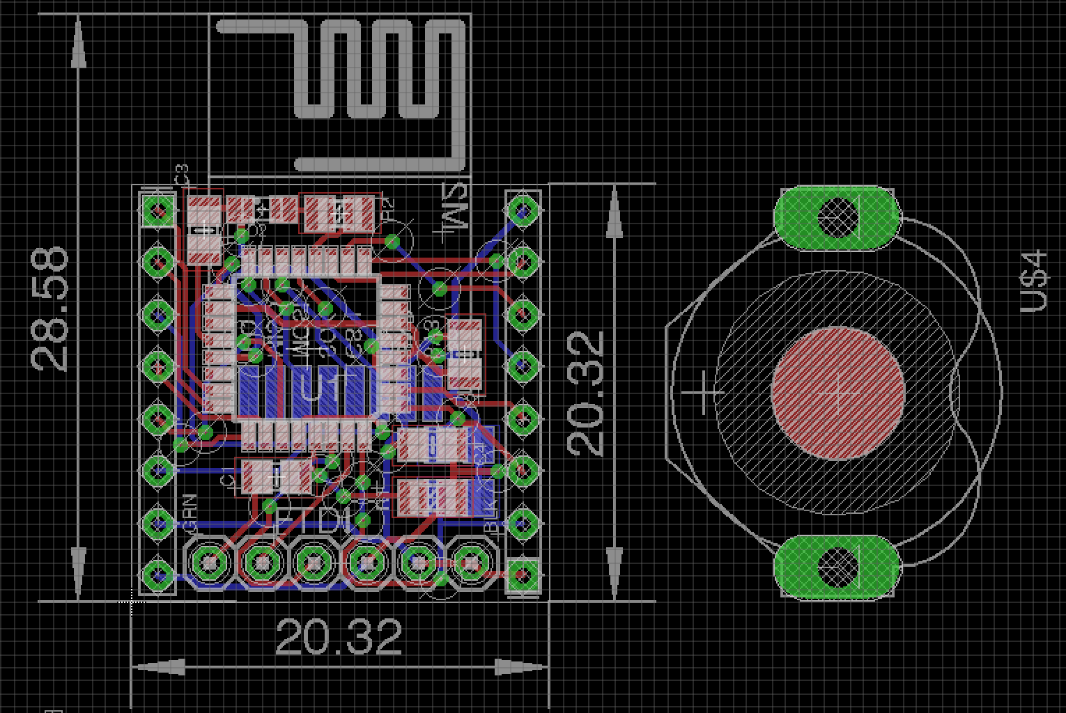
      The node sends new distance measures to the controller only when they change. As I wanted to be able to remotely switch the relay at my discretion, the node itself is not battery based, but always on. I'm using a PCB I designed which you can find on Openhardware.io:
      https://www.openhardware.io/view/11/ACDCBatteries-capable-atmega328p-board

      You can use any relay module which can be controlled by a digital pin.

      I use the PA+LPA version of the nrf24l01+ radio, since the basement is covered by a slab of metal re-inforced concrete. A normal radio did not reach the gateway.

      I have added the sketch below:

      0_1472292343284_BasementAlarmUltrasonic.ino

      posted in My Project
      GertSanders
      GertSanders
    • RE: What did you build today (Pictures) ?

      One of three ongoing projects:

      0_1526832472969_IMG_0418.jpg

      0_1526832993103_IMG_0422.jpg

      lasercut box
      atmega1284p based
      DS3231 rtc (very accurate and 2 alarms!)
      LDR
      20 by 4 LCD, two sizes of numbers, menu driven setup
      buzzer
      leds for moodlighting
      doppler for proximity detection
      encoder for scrolling through values (for setting time)
      buttons with LED feedback for interactivity
      mp3 player
      most interface objects MySensorised ๐Ÿ™‚

      This entry is to boost my energy, because we are still a long way from home (pcb is still not made, focus is now on prototype and software).

      posted in General Discussion
      GertSanders
      GertSanders
    • 50mm x 50mm board with different powering options

      Still testing this PCB, but so far everything is working. I now have a board which I can use in different power configurations.
      Upper left is powered by 220V AC directly, an HLK-PM01 takes care of bringing that down to 5V. The radio gets power from an AMS1117-3V3 mounted on the bottom side of the board.
      Top right is a board powered by 12VDC, with conversion (a 3A DC-DC step-down module) to 4V for the SIM800L (GSM module) and this is dropped to 3.5V by passing a rectifier diode, for the radio. Both are running repeater code in combination with some sensor code.
      In the middle the version based with two AAA batteries, which I still need to assemble. It will be interesting to see if this also has a sleep current consumption of 1.45 uA like it's little brother (my GSRedboard)

      I will do a writeup later, as I have a few improvements in mind, and I prefer to test everything first.

      Just to show that using the Mysensors library allows me freedom to make stuff I (think) I need :-).

      IMG_7579.jpg
      IMG_7564.jpg
      IMG_7570.jpg
      IMG_7575.jpg
      IMG_7582.jpg

      posted in My Project
      GertSanders
      GertSanders
    • RE: Your workshop :)

      Here is the corner I share with my wife. Each has a desk, but since I was first to start this and need both a mental (my Mac) and physical workspace , my desk is a little wider ๐Ÿ™‚

      Never mind the distortion, it's a badly made panorama, but gives a good idea of where I spend my free time.

      0_1459677584874_IMG_7850.jpg

      posted in General Discussion
      GertSanders
      GertSanders
    • RE: Your workshop :)

      @Samuel235

      I do indulge in "suikerwafel" to keep my brain happy. My wife keeps me young. Running on occasion also helps. Never tried protein, does Rochefort 10 count ?

      posted in General Discussion
      GertSanders
      GertSanders
    • RE: Your tools :)

      I have a Weller EC-2002 soldering station with a narrow point soldering iron (I also have the standard one, but never use it, too big for delicate work).

      0_1459969864605_IMG_7860.jpg

      Stereo binoculars (20x magnification) with lamp to see those fine traces.

      0_1459969932268_IMG_7861.jpg

      My trusted Fluke 87 mark 4

      0_1459969970540_IMG_7864.jpg

      A large breadboard (and a few smaller ones):

      0_1459970056634_IMG_7865.jpg

      My power supply is a repurposed old PC power supple (gives a fixed 12V and 5V).

      0_1459970102173_IMG_7868.jpg

      Some tweezers and cutters.

      0_1459970136181_IMG_7870.jpg

      A magnifying lamp when the micro is overkill, it's also my desk lamp.

      0_1459970176174_IMG_7873.jpg

      I use an iMac with a 27 inch screen and 4GHz cpu for most of my software. Sometimes it is necessary to use Windows, which I do within a Virtual Box (e.g. to compile boot loaders with WinAVR2010).

      And even with this supercomputer on my desk, I still use my trusted HP-41CX with the Advantage module (since 1985, I had an overclocked HP-41 with magnetic card reader from '82 to '84 but it was stolen from me) for most of my electrical calculations. I lost count how many times I changed the batteries, but it is about every 10 months on average I think.

      0_1459970801358_IMG_7874.jpg
      0_1459970811989_IMG_7875.jpg

      Still on my wish list:

      • a dual power supply with voltage and current setting/indicators (not decided on the model yet)
      • a logic analyser (Saleae Logic 8 Pro, or 16 Pro if the donor is generous, in red !)
      • a second high res screen (5K at least ๐Ÿ™‚ ), no options available yet
      posted in General Discussion
      GertSanders
      GertSanders
    • RE: Your workshop :)

      I moved my desk to a new spot in the house and reoriented the desk. Still a mess, but that is how my mind seems to work these days: lots of stuff in parallel ...

      0_1524596593672_IMG_0371.jpg

      posted in General Discussion
      GertSanders
      GertSanders
    • RE: New nrf24l01+ smd

      @AWI No problem, this board is making its way to me via the mail now (was shipped from OSH Park last wednesday).

      I'm hoping to test it coming week.

      This board one is a one-trick pony. It is based on @m26872's concept of a very narrow board, but in my case I just need it to handle 2 magnetic switches. So pull-up resistors and connection for two contacts (normally closed) is provided (on the pins that allow hardware wake up from power down), and nothing else. No crystal, just minimal power decoupling and a led. No FTDI adapter or ISP. And of course only connection for the SMD version of the NRF24.

      0_1454851622651_Screen Shot 2016-02-07 at 14.22.03.png

      0_1454851679505_Screen Shot 2016-02-07 at 14.21.41.png

      While that was being made at OSH Park I prepared a second design, but this one is still in movement (not ordered yet), measurements are in mm:

      0_1454852947623_Screen Shot 2016-02-07 at 14.47.56.png

      It is certainly not a Sensebender, as it lacks ATSHA204A, SI7021 and SPIFlash, but it does have FTDI interface and optional pull-ups on D2 and D3. It is my first try at SMD, with 0805 size components (I need to be able to hand solder them).

      The objective is to make a working sensor board as flat as possible. At the moment is is even smaller then the CR2032 batteryholder I was planning to use. A possibility is that I go for a two board approach using this "flat node" and a second board to hold a CR1632 (a holder for this smaller battery is in the image above, Keystone Technologies model 3013).

      To be continued ...

      posted in Hardware
      GertSanders
      GertSanders
    • Domoticz as controller **and** a gateway for MySensor nodes running on a Raspberry Pi 2

      Just to let all know that I'm quite happy with my current setup: Domoticz as controller and a gateway running on a Raspberry Pi 2.

      The serial gateway I use is made of a small board sitting on the GPIO pins of the same Raspberry.
      The PCB for this gateway is public (https://oshpark.com/shared_projects/aXLXBO3f), the code to run is available from the Mysensors raspberry implementation. This creates a serial port which then needs to be represented via a symbolic link with a short name, so that Domoticz can see it.

      This allowed me to eliminate a physical gateway, since the raspberry runs as a gateway and a controller at the same time.

      Many thank to the MySensors team for the sensor software (same shoutout to the Domoticz designers) ๐Ÿ™‚

      IMG_7264.jpg IMG_7265.jpg IMG_7266.jpg IMG_7267.jpg

      posted in My Project
      GertSanders
      GertSanders
    • OTA flash types for MySensors

      I thought it would be useful to compile a list of flash memory compatible with DualOptiboot and other OTA capable bootloaders.

      So the plan is to pin this message and add SPI based Flashmemory typenumbers/brands and how they are connected to the relevant OTA bootloader.

      I know most bootloaders require SPI based flash memory. I have found 1 article describing a bootloader which allows the use of I2C EEPROM (http://www.rotwang.co.uk/projects/bootloader.html). But this is outside scope of MySensors for the moment.

      So for following OTA' BL's:

      DualOptiboot:

      Allows a maximum sketch size of 64Kbytes. People with atmega1284p and 130KByte sketches are out of luck.
      From the designnotes of DualOptiboot:

      Limited to 31K sketches for atmega328p and 64K sketches for atmega1284P


      DualOptiboot is based on Optiboot 5.0

      Brand, modelnumber, connectiontype, capacity, voltage-range

      Adesto Technologies, AT25DF512C-SSHN-B, SPI, 65Kbyte (512Kbit), VCC = 1.65V - 3.6V
      Bondwell, partnumber_unknown, SPI, 64KBytes
      etc ....

      MYSBootloader:
      ...

      As you answer I will add this info to this first message.

      Maybe more details need to be compiled if they are necessary for compatibility with the bootloaders specified. Feel free to comment on this as well

      posted in Hardware
      GertSanders
      GertSanders
    • RE: 50mm x 50mm board with different powering options

      To make it a bit easier for some, here are the EAGLE files of this AC capable board.
      AC based repeater V3.sch
      AC based repeater V3.brd
      AC based repeater V3 partlist.txt
      AC based repeater V3.pdf

      posted in My Project
      GertSanders
      GertSanders
    • RE: ๐Ÿ’ฌ Very narrow and minimal switch node

      The very narrow boards v1-1 have arrived ๐Ÿ™‚

      0_1456950291190_IMG_7800.jpg

      0_1456950446982_IMG_7801.jpg

      posted in OpenHardware.io
      GertSanders
      GertSanders
    • RE: What did you build today (Pictures) ?

      So here is my contribution to this tread: a differential drive "brain". A work in progress:

      0_1525210230419_IMG_9439.jpg

      posted in General Discussion
      GertSanders
      GertSanders
    • RE: PCB Boards for MySensors

      Below you will find a link to a board I made and now use with the MySensors library and EasyIOT.

      https://oshpark.com/shared_projects/qnkNIMZx

      This is a version with the small nRF24L01+. I'm now working on a version using the longer board version (with SMA antenna).

      posted in Hardware
      GertSanders
      GertSanders
    • RE: My basement flooding alarm

      @Nca78

      The reason I use the ultrasonic sensor is because I do not like to put a wire along the wall and a sensor on ground level. Now I only have a small case at cabinet level, with the US sensor directed to the floor. And I can measure any water level up to 255 cm with this.

      A collegue of mine uses this same node to measure the amount of rainwater collected in his rainwater tank.

      In Domoticz I have set up several triggers so that I get notifications on specific waterlevels. This is needed if waterlevels keep rising while the pump is working, meaning the pump can not handle the flooding and needs to be assisted by extra equipment.

      posted in My Project
      GertSanders
      GertSanders
    • RE: ๐Ÿ’ฌ Very narrow and minimal switch node

      @alexsh1

      Here are some images of the very narrow node in a 16x16mm cable duct. The batteries are AAA type.

      0_1457556053405_IMG_7814.jpg

      0_1457555980720_IMG_7812.jpg

      0_1457555993984_IMG_7810.jpg

      0_1457556003354_IMG_7809.jpg

      posted in OpenHardware.io
      GertSanders
      GertSanders
    • RE: What did you build today (Pictures) ?

      @vladimir

      you could use this under the bed:

      https://www.aliexpress.com/item/Free-Shipping-5-Pieces-RCWL-0516-Microwave-Radar-Sensor-Module-Human-Body-Induction-Switch-Module/32773310756.html?spm=a2g0s.9042311.0.0.27424c4dQaNm0K

      It works like an infrared sensor (same three pins), but it does not need a line of sight. It just reacts to movement as this results in a disturbance in the emitted radio signal. Works very well on my clock ๐Ÿ™‚

      The "high" value when movement is detected is not a full 5V, so I test the Out pin as an analog pin. Anything above 2.5V is an activation due to movement.

      posted in General Discussion
      GertSanders
      GertSanders
    • RE: Yet another PCB to address (nearly) all Arduino pins

      @phil83
      Share this on OpenHardware.io !

      posted in Hardware
      GertSanders
      GertSanders
    • RE: ๐Ÿ’ฌ Various bootloader files based on Optiboot 6.2

      @*alexsh1
      *
      Which fuses are set when loading a boot loader is defined by wich menu element in tools you have selected. Every processor or board you choose will correspond with values in a board.txt file.

      You can have several board.txt files: 1 file per "family" of boards.

      When uploading sketches, the fusesettings are ignored, only the uploadspeed counts then. Both when uploading with Arduino as ISP as with FTDI interface.

      The internal oscillator of 8 Mhz is not as accurate as a crystal, so at higher uploadspeeds the errorrate can increase or decrease depending on the mcu temperature.

      Some uploadspeeds are closer to optimal then others in relation to the frequency at which the mcu works. The baudcalculator shows the errorrates. Most are non optimal. avrdude can handle an errorrate of 2% or less. So using a specific baudrate in combination with the internal 8Mhz oscillator depends on the worst case combination of transmission errorrate plus clock deviation error.

      For most mcu's the rate of 9600 baud will be acceptable because at that slow rate a clockerror will be relative small. At higher speeds the small clockerror becomes more important. Then it is best to choose an upload speed close to the optimum.

      The fusesettings are only burnt when loading a boot loader (within the Arduino IDE, in AVRStudio you can set fuses seperatly from loading anything).

      The frequency of 8 Mhz can be obtained via a 8mhz crystal or the internal 8mhz oscillator. The low fuse value 0xE2 sets this internal oscillator. By using value 0x62 you also set the clock division bit in combination with the 8mhz internal oscillator, so your mcu will run at 8mhz / 8 = 1mhz

      There are other division values possible. Calculate the low byte value using an avr fuse calculator.

      You can also use an external 8 mhz crystal, and combine this with clock division by 8 to get 1mhz operation.

      And you can choose an external 1mhz crystal.

      All this from choose the right fuse bits.

      Same for Brown out Detection which is set via the three least significant bits of the extended fuse.

      posted in OpenHardware.io
      GertSanders
      GertSanders
    • RE: ๐Ÿ’ฌ Battery Powered Sensors

      @Efflon

      VCC pin is directly connected to the MCU.

      The RAW or IN pin is connected to the regulator input. Th eregulator output is connected to VCC pin and thus to the MCU power input pin.

      On a 3V3 promini you can give between 3V3 and 12V (on most promini's, some can handle up to 16V) on the RAW or IN pin. The regulator on the promini will bring that down to 3V3 (which you will be able to measure on the VCC pin).

      By giving 3V3 on the VCC pin, some power is lost via the output pin of the regulator (through the regulator) towards the GND pin of the regulator. This should be minimal, but on bad regulators it can be enough to drain a battery in weeks. So yes, I would cut the regulator output line when giving power via VCC.

      Cutting the line of the powerLED (on either side of it, doesn't matter) will make sure that the LED does not drain the battery either. This LED can pull between 5 -15mA depending on the protection resistor that sits in series with it.

      So VCC pin and RAW pin are NOT the same.

      posted in Announcements
      GertSanders
      GertSanders
    • RE: Longer sleep values for Watchdogtimer interrupt?

      I had some time yesterday to experiment with the Lowpower library and answered my own question.

      Conclusion: you can set the divider to a higher value then 10 (10 is used to test on permanent deep sleep by the Lowpower lib, and Mysensors lib as well I think), but it does not matter, the atmega328 ignores any value above 9, so 8 seconds is the longest deep sleep you can get. Oh well, worth a try.

      posted in Development
      GertSanders
      GertSanders
    • RE: ๐Ÿ’ฌ My simple RFM dongle for Serial GW

      @TheoL
      Huh ? Did someone say beer ?

      posted in OpenHardware.io
      GertSanders
      GertSanders
    • RE: ๐Ÿ’ฌ Various bootloader files based on Optiboot 6.2

      I have added my atmega328 directory in a RAR file and uploaded it to the site.

      This compressed file contains a directory structure that contains all bootloaders I use, and the extra files needed to make most of those available from the Arduino IDE.

      To use it:
      Close the Arduino IDE
      Unpack the RAR file
      Open the IDE

      This compressed file needs to be unpacked inside the "hardware" directory which sits inside the Arduino Sketches directory. If you do not have a "hardware" directory inside the Arduino Sketches directory, then you need to make this first.
      Then go inside the "hardware" directory and there unpack the RAR file.

      My directory structure looks like this:

      [Arduino]
         [hardware]
            [atmega328p]
               [avr]
                  [bootloaders]
                     [myoptiboot]
                        ... all the HEX files ...
                  [variants]
                     [28PinBoard]
                        pins_arduino.h
                     [32PinBoard]
                        pins_arduino.h
                     [40PinBoard]
                        pins_arduino.h
                     [44PinBoard]
                        pins_arduino.h
                  boards.txt
                  platform.txt
      
      posted in OpenHardware.io
      GertSanders
      GertSanders
    • RE: [Tutorial] How to burn 1Mhz & 8Mhz bootloader using Arduino IDE 1.6.5-r5

      Here are all the possible values:

      bootloader.extended_fuses=0x04 -> BOD at 4.3V
      bootloader.extended_fuses=0x05 -> BOD at 2.7V
      bootloader.extended_fuses=0x06 -> BOD at 1.8V
      bootloader.extended_fuses=0x07 -> BOD disabled

      posted in Development
      GertSanders
      GertSanders
    • RE: ๐Ÿ’ฌ Battery Powered Sensors

      @Meshx86
      The corrective value is needed every time you change a battery, AND if you need high accuracy.
      On my battery based nodes I do not have a need for absolute accuracy, I just need to see the trend of the Vcc value.
      Changing the battery happens every 12-24 months (depends on the use), so I'm not very interested in absolute accuracy. If you need real accurate measuring, I would suggest a real Analog-To_Digital chip.

      posted in Announcements
      GertSanders
      GertSanders
    • RE: ๐Ÿ’ฌ Various bootloader files based on Optiboot 6.2

      If anyone uses the bootloaders, please leave a message here with your experience. It would be nice to know which one of the bootloaders are effectively used.

      I know some combinations of CPU clock and upload speed do not make sense, so those will be removed. But for the moment I leave them in the project.

      I have succes with the following versions:

      Used on the very narrow board:
      optiboot_atmega328_08M_038400_B0.hex (on V 1-0)
      optiboot_atmega328_08M_038400_D6.hex (on V 1-1)

      Used on my AC based board:
      optiboot_atmega328_08M_038400_B0.hex
      optiboot_atmega328_16M_057600_B0.hex

      posted in OpenHardware.io
      GertSanders
      GertSanders
    • RE: How to assign static node ID?

      Here are the defines I put in my sketches for the development library:

      //#define MY_NODE_ID 1
      //#define MY_PARENT_ID 0
      
      // Possible values for Arduino IDE: 9600, 19200, 38400, 57600, 74880, 115200, 230400, 250000
      // The last three values are only possible if the mcu works at 16Mhz or more, not possible for 8MHz operation.
      //#define MY_BAUD_RATE 57600
      
      //#define MY_RADIO_NRF24
      //#define MY_RADIO_RFM69
      
      // Enable serial gateway
      //#define MY_GATEWAY_SERIAL
      
      // Enabled repeater feature for this node
      //#define MY_REPEATER_FEATURE
      
      // Flash leds on rx/tx/err
      //#define MY_LEDS_BLINKING_FEATURE
      // Set blinking period
      //#define MY_DEFAULT_LED_BLINK_PERIOD 300
      
      // Enable inclusion mode
      //#define MY_INCLUSION_MODE_FEATURE
      // Enable Inclusion mode button on gateway
      //#define MY_INCLUSION_BUTTON_FEATURE
      // Set inclusion mode duration (in seconds)
      //#define MY_INCLUSION_MODE_DURATION 60
      // Digital pin used for inclusion mode button
      //#define MY_INCLUSION_MODE_BUTTON_PIN  3
      
      //#define MY_DEFAULT_ERR_LED_PIN 5  // Error led pin
      //#define MY_DEFAULT_RX_LED_PIN  6  // Receive led pin
      //#define MY_DEFAULT_TX_LED_PIN  7  // the PCB, on board LED
      
      // possible values: RF24_PA_LOW (is default on gateway), RF24_PA_MED, RF24_PA_HIGH, RF24_PA_MAX (is default on nodes)
      //#define MY_RF24_PA_LEVEL RF24_PA_HIGH
      
      // RF channel for the sensor net, 0-127. Channel 76 is the default in all library examples
      //#define MY_RF24_CHANNEL     76
      
      //RF24_250KBPS for 250kbs (default), RF24_1MBPS for 1Mbps, or RF24_2MBPS for 2Mbps
      //#define MY_RF24_DATARATE      RF24_250KBPS
      
      
      posted in Development
      GertSanders
      GertSanders
    • RE: New option: SMS gateway

      The capability to send SMS is not really needed in the MySensors library itself, but the Adafruit FONA library works together with the MySensors library (DEV version anyway).

      I added a sketch which make a node a SMS gateway if it is equipped with a SIM800L module. You can find it on Openhardware.io:

      https://www.openhardware.io/view/11/ACDCBatteries-capable-atmega328p-board

      The sketch is available under the design files and is now part of the MySensors library examples (again in the development version only).

      If you want to get notified of the fact that your internet connection is down, you will need to make something on the controller side to notice this and then send a V_TEXT to the node itself, or change a "switch" on the node, so that it can trigger the sending of a SMS.

      posted in Feature Requests
      GertSanders
      GertSanders
    • RE: My own board (50mm x 30mm)

      Second variant with the same board. This one actually sends it's messages better (no more st:fail's):

      IMG_7380.jpg IMG_7383.jpg

      And it's nice and compact. Now I need to find a nice ventilated little box to protect them from dust.

      This board is now tested and shared on OSHPark: https://oshpark.com/shared_projects/unP8BmuI

      Component values are mentioned in the brd file. I will add a BOM in Excel format later.

      posted in My Project
      GertSanders
      GertSanders
    • RE: ๐Ÿ’ฌ Very narrow and minimal switch node

      The latest member of my growing sensor family, a reedswitch sensor with wakeup from power down by change on pin 2, wakeup every 23 hours to report battery voltage, and of course a blinky light when these things happen ๐Ÿ™‚

      0_1456959867067_IMG_7804.jpg
      1_1456959867067_IMG_7805.jpg
      2_1456959867067_IMG_7807.jpg

      Just tested and found to be OK. Next board will be set up for using a I2C module (will be my smallest temperature sensor yet). Time for a glas of WestVleeteren and rest.

      posted in OpenHardware.io
      GertSanders
      GertSanders
    • RE: Need some help on how to burn a sketch with SlimNode and 1MHz Bootloader

      @drock1985

      From the earlier compile warnings I think you should do a clean install of the IDE 1.6.8
      The warnings show "leftovers" from earlier versions and this results in the warnings you see.

      Also do not just backup and recopy your older libraries, but use the library manager in the IDE to get the latest versions.

      Then add your older sketches back to the new sketches directory (I would really advise to start clean).

      I have added a ZIP file which is the compressed version of my subdirectory of boards and boot loaders.

      This needs to be unpacked in the sketches directory in a folder called "hardware"

      .0_1461177747340_Screen Shot 2016-04-20 at 20.42.16.png

      The detail (after unpacking would be like this:

      0_1461177879118_Screen Shot 2016-04-20 at 20.43.48.png

      0_1461177891459_Screen Shot 2016-04-20 at 20.44.04.png

      So the ZIP below needs to be expanded inside the "hardware" directory of the sketches folder.

      0_1461177773326_atmega328p.zip

      After that I would do another attempt to write the boot loader and then try with the FTDI on a different COM port or USB interface.

      posted in Troubleshooting
      GertSanders
      GertSanders
    • RE: My own board (50mm x 30mm)

      @ahmedadelhosni It probably depends on the other boards put on the same panel. A boardhouse makes PCB's in large panels. They fit as much designs as they can on these boards. If you need exactly 10, they will give priority to your design (and it costs more); if not needed, they can add your design to a board and if that means 9 PCB's only, that would be acceptable. For my blue board design I received 11 PCB's, for the red board I received 12, but I would have been OK with 9 or 10 also (given the low price and good quality).

      For prototyping I think this is a very good deal. The only minor point: transport time is VERY long, in my case it is 4 weeks between notification that the PCB's are shipped to me and actual delivery to my mailbox. Production is about 1 week. So if you have time (count 5-6 weeks) to get your boards, then DirtyPCB is very good value. If you need prototypes faster (at a little higher expense) I suggest you use OSHPark. You will only get 3 PCB's, but they will be delivered faster (about 3 weeks in my case).

      posted in My Project
      GertSanders
      GertSanders
    • RE: ๐Ÿ’ฌ Various bootloader files based on Optiboot 6.2

      @alexsh1

      I just tested with the 9600 baud version at 1MHz, and the blink sketch at 250ms, 500ms and 1000ms per on/off cycle. All rock solid and as expected.

      Here is the setup I tested the transfer with FTDI:

      0_1457556540048_IMG_7815.jpg

      0_1457556805834_IMG_7816.jpg

      I used the following combination:

      Boot loader:

      0_1457556618255_optiboot_atmega328_01M_009600_B0.hex

      Fuses:
      BlueBoard.menu.mhz.1Mi= 1Mhz - internal 8MHz DIV 8 - 9K6 upload speed
      BlueBoard.menu.mhz.1Mi.bootloader.low_fuses=0x62
      BlueBoard.menu.mhz.1Mi.bootloader.high_fuses=0xDE
      BlueBoard.menu.mhz.1Mi.build.f_cpu=1000000L
      BlueBoard.menu.mhz.1Mi.upload.speed=9600
      BlueBoard.menu.mhz.1Mi.bootloader.file=myoptiboot/optiboot_atmega328_01M_009600_B0.hex

      Also here the "0_1457556618255_" is added by uploading on this forum, strip when downloaded.

      Uploads were at twice the speed then before. Still slow, but acceptable.

      posted in OpenHardware.io
      GertSanders
      GertSanders
    • RE: PCB Boards for MySensors

      Regarding MYSX tags, I would provide tags for following versions as a minimum:

      No_MYSX
      MYSX1.0
      MYSX1.1
      MYSX1.2
      MYSX1.3
      MYSX1.4
      MYSX1.5

      The designers could then tag with the version they have implemented in their hardware

      If the MYSX connector specification becomes (or is) the official MySensors connector spec, then I think a dedicated field where one chooses the version supported would make more sense than a free tag field.

      posted in Hardware
      GertSanders
      GertSanders
    • RE: 50mm x 50mm board with different powering options

      The battery version of the board also works. Below it is in a light sensor version. A repeater was made as well.

      The battery version:

      IMG_7596.jpg
      IMG_7599.jpg
      IMG_7602.jpg
      IMG_7594.jpg

      The repeater:

      IMG_7586.jpg
      IMG_7589.jpg
      IMG_7585.jpg

      posted in My Project
      GertSanders
      GertSanders
    • RE: Battery based atmega328p sensor with SMD nrf24l01+

      Added BOM, EAGLE files, board image and a warning: untested board !

      posted in OpenHardware.io
      GertSanders
      GertSanders
    • RE: ATMega328p/Arduino Interupt enabled pins?

      @samuel235 The MySensors library does not use INT0 for the NRF24, so there are in fact 2 pins available. If your board connects the NRF24 interrupt pin (8) with D2, then of course you can not use the pin for a switch anymore. But on a node which sleeps until a switch is tripped, there is no point in connecting the INT of the NRF24 with D2, as the radio will also sleep most of the time.
      The two pins D2 and D3 can wake up the ATMEGA328 from it's deepest sleepstate, which is the one you go into when using the call gw.sleep(0).
      I use sleep(0, LOW, 1, LOW, 0) when going to sleep. Both D2 and D3 are pulled up with 10M resistors, the reeds switches pull these pins low when contact is made (mine are of the normally open type and close when the magnet is moved away from them) to wake up the processor.

      posted in Hardware
      GertSanders
      GertSanders
    • RE: My own board (50mm x 30mm)

      @alexsh1 It is based on my AC capable board, is a normal atmega328p board, but with a SIM800L mounted on it. This module allows me to send and receive SMS's, and I use one of the digital output pins to control a waterpump. I have a second AC based board ready which will be my MySensors SMS gateway. This means it will be able to receive V_TEXT and send that to the default GSM number as a SMS. It should be possible to receive SMS and send that as V_TEXT to other nodes, but so far I have not started the design of the second sketch yet.

      1447344753891-img_7575.jpg

      You see it here also (top right) with the relay module and the white AC-DC converter connected.

      1447344662709-img_7579.jpg

      Side view:

      1447344891388-img_7582.jpg

      posted in My Project
      GertSanders
      GertSanders
    • RE: ๐Ÿ’ฌ MySensors Stable Node

      Congratulations !!! Best hardware project indeed !

      posted in OpenHardware.io
      GertSanders
      GertSanders
    • RE: Yet another PCB to address (nearly) all Arduino pins

      A7 is an analog input only pin. So connecting a LED will not work. In the MySensor library the atsha204a is expected on A3.

      posted in Hardware
      GertSanders
      GertSanders
    • RE: Your tools :)

      @sundberg84
      As requested here are a few detailed images of my repurposed PC power supply.
      For those with fancy lab power supplies: I also want that, but for now I make do with this:

      0_1460134229535_IMG_7878.jpg
      0_1460134287860_IMG_7879.jpg

      I ripped it from a PC I built in 1998, and added two things: a switch and an "interface cable"

      The switch:

      1_1460134303711_IMG_7882.jpg
      0_1460134303711_IMG_7881.jpg

      The "interface cable":

      0_1460134359218_IMG_7883.jpg
      1_1460134359218_IMG_7884.jpg

      The end result is plugged into my breadboard and gives me 12V (yellow), 5V (red) and GND. Too bad it does not give 3.3V, but that was not on the radar yet in '98.

      I could probably do better and put all this in a nice case, but I want displays showing voltage and current, so I plan to buy a real bench power supply (like a real grown up ๐Ÿ™‚ ).

      posted in General Discussion
      GertSanders
      GertSanders
    • RE: ๐Ÿ’ฌ Various bootloader files based on Optiboot 6.2

      @Samuel235

      So here is my update: on my board I was able to upload my boot loader for 8MHz internal oscillator, with 34K8 upload speed and a led on pin D8. Here is the board running the "blink" sketch:

      0_1460809876803_Screen Shot 2016-04-16 at 14.26.47.jpg

      To make life easier I have zipped my complete folder, which I keep under the "hardware" folder in the sketches folder:

      0_1460809951141_atmega328p.zip

      I started with loading the ISP sketch on my Uno compatible board (it is set up for loading boot loaders on DIL type of atmega328):

      0_1460810124544_IMG_7912.jpg

      Then I choose the following settings in the Arduino IDE:

      0_1460810237368_Screen Shot 2016-04-16 at 14.36.25.jpg

      After choosing these settings I selected "Burn Bootloader", which resulted in a good loading. Since there is no sketch yet, my board cycles through a reset fase (and thus the LED blinks three times every few seconds).

      After that I selected my FTDI interface and uploaded the BLINK sketch with the same settings, and bingo: blinky lights.

      My next step will now be to add the radio and do a LED dimming test, to be continued ...

      posted in OpenHardware.io
      GertSanders
      GertSanders
    • RE: Your workshop :)

      @Damme

      For more IO you could use an I2C based I/O extender chip.
      There is also MCP23017 (also available in DIL format) which is a 16-Bit I/O Expander with Serial Interface (exists in SPI and I2C versions). This gives an atmega328 an extra 16 digital pins with just SDA and SCL !

      PCA9685 is also an I2C driven expander which has 16 channels which can be used for PWM (driving servo's) or as normal digital Input or Output pins. Each channel can be set in it's own way, independent from the other channels. There is no DIL version of this chip, but a breakout exists on Aliexpres (quite cheap).

      So there are some options if an extra cpu is not desirable.

      posted in General Discussion
      GertSanders
      GertSanders
    • RE: ๐Ÿ’ฌ Sensebender Micro

      A version with the SMD NRF24L01+ would be cool !

      posted in OpenHardware.io
      GertSanders
      GertSanders
    • RE: What did you build today (Pictures) ?

      @neverdie nope, but it is inspired by oriental frames, I just made that based on what I saw on one of my cabinets (which I bought while living in Singapore).

      posted in General Discussion
      GertSanders
      GertSanders
    • RE: ๐Ÿ’ฌ Sensebender Micro

      @RJ_Make
      Certainly possible, check the examples.

      posted in OpenHardware.io
      GertSanders
      GertSanders
    • RE: ๐Ÿ’ฌ mobile robotics - a discovery path

      After a lot of revisions, changes, corrections and doubting, I finally decided to commit to a first board production. We will see if this comes out good. The design is still untested. Just reporting on the progress (which is glacially slow).

      posted in OpenHardware.io
      GertSanders
      GertSanders
    • RE: OpenHardware.io

      @hek Very happy with the file removal option! Makes maintaining the info better.

      posted in Announcements
      GertSanders
      GertSanders
    • RE: Meetup in the Netherlands - Saturday July 30th, in Breda!

      By this summer the City of Things lab in Antwerpen should be taking shape. Getting a MySensors gateway running and communicating with the platform we plan to build for CoT would be a great topic for a meet at my workplace, since we are the IT department of the City of Antwerp.
      There are already several meetups on this topic, and more to come.
      To give an idea why we do this:
      https://www.iminds.be/en/succeed-with-digital-research/city-of-things

      posted in General Discussion
      GertSanders
      GertSanders
    • RE: MyController.org

      http://forum.mysensors.org/topic/1974/domoticz-as-controller-and-a-gateway-for-mysensor-nodes-running-on-a-raspberry-pi-2

      My setup described here

      posted in MyController.org
      GertSanders
      GertSanders
    • RE: Battery based atmega328p sensor (no SMD)

      As mentioned, work in progress ...

      posted in OpenHardware.io
      GertSanders
      GertSanders
    • RE: ๐Ÿ’ฌ Battery Powered Sensors

      Here is a view of a node running exactly 1year. The effect of a bad radio is seen here as the fast voltage drops. I had a very low charged battery to start with, replaced it with new batteries which also discharged fast, and replaced both batteries and the radio. Since mid january 2016 the node has been running as expected. My guess is that this combo will run for 2 years (given how it has been working the past 9 months).

      This node measures battery voltage, temperature and humidity and sends 3 messages about every 5 minutes.

      0_1474202873202_Screen Shot 2016-09-18 at 14.41.30.png

      And here is the battery measurement of the second node that went "online" the same day (18/sep/2015, with a good radio, and similarly used batteries from the start). This node sends very few messages (at least 1 every 24 hours, and when one of 3 contacts are opened). Most days it just sends 1 message.

      0_1474203476121_Screen Shot 2016-09-18 at 14.55.05.png

      So even with batteries already at a low level, you can make useful nodes using the MySensors setup ๐Ÿ™‚

      posted in Announcements
      GertSanders
      GertSanders
    • RE: What is the minimum distance between main voltages (PCB)

      @ahmedadelhosni

      In my DRU I use 100 mil clearance for AC lines (and 100 mil width).

      posted in General Discussion
      GertSanders
      GertSanders
    • Adapter for RFM69 on NRF24L01+ pinout-header

      Has anyone made or purchased an adapter to connect the RFM69 to a header with connections for nRF24L01+ ?

      Such a header uses the following Arduino pins:

      1: GND
      2: 3V3
      3: CE (pin 9)
      4: CSN (pin 10 or SS)
      5: SCK (pin 13)
      6: MOSI (pin 11)
      7: MISO (pin 12)
      8: IRQ (not used)

      The RFM69 will need an interrupt pin, most likely D2 (pin 3 on the atmega328p).

      posted in Hardware
      GertSanders
      GertSanders
    • RE: ๐Ÿ’ฌ Very narrow and minimal switch node

      @jacikaas: to program the processor, you need to remove it from the board and program it on a breadboard or another board with ftdi interface.
      But you can load a sketch like the humidity sensor sketch if you add a I2C sensor like a SI7021. I plan to do just that.

      posted in OpenHardware.io
      GertSanders
      GertSanders
    • RE: Domoticz as controller **and** a gateway for MySensor nodes running on a Raspberry Pi 2

      some more imagesthumb_IMG_7286_1024.jpg IMG_7288.jpg IMG_7289.jpg
      IMG_7290.jpg
      IMG_7291.jpg

      IMG_7292.jpg IMG_7298.jpg IMG_7295.jpg

      posted in My Project
      GertSanders
      GertSanders
    • RE: Your workshop :)

      @Samuel235
      I would have sworn it was protein-like :-), oh well, we learn everyday ...

      posted in General Discussion
      GertSanders
      GertSanders
    • RE: PCB Boards for MySensors

      Here is my version of a compact board for inclusion in the list. This board is equipped with two connectors for NRF24 (so you can choose the orientation of the radio) and uses the MySensors libs. Works in five rooms in my house now.
      http://forum.mysensors.org/topic/1901/my-own-board-50mm-x-30mm/38
      Eagle files are added:
      selfcontained low power node v1.sch
      selfcontained low power node v1.brd
      BOM:
      selfcontained-low-power-node-v1.csv
      Schematic in PDF format:
      selfcontained low power node v1.pdf
      A panelised version (could be cleaner but works):
      selfcontained low power node v1 panelised.brd

      Links to manufacturers:
      https://oshpark.com/shared_projects/unP8BmuI (single boards)
      http://dirtypcbs.com/view.php?share=11770&accesskey=5f9f38337641290cf017475f1b91ff81 (panelised version)

      My version of Optiboot for this board assumes the flashing LED is connected to pin 8 (as is on my board):

      optiboot_atmega328_8Mhz_B0.hex

      And here are my settings for the board.txt file:

      ###############
      possible upload speeds: 9600, 14400, 19200, 28800, 38400, 57600, or 115200
      for 8MHz we keep this slower to avoid transmission errors.
      First settings are for use without a crystal, internal oscillator at 8MHz and Brown Out Detection switched off (to save batteries even more).
      Second settings are for use with an external 8MHz crystal (better stability of frequency) and Brown Out Detection switched off (to save batteries even more).
      ###############

      atmega328pO4M8i.name=atmega328p Optiboot4 8MHz - internal osc. no BOD

      atmega328pO4M8i.upload.tool=arduino:avrdude
      atmega328pO4M8i.upload.protocol=arduino
      atmega328pO4M8i.upload.maximum_data_size=2048
      atmega328pO4M8i.upload.maximum_size=32256
      atmega328pO4M8i.upload.speed=38400

      atmega328pO4M8i.bootloader.tool=arduino:avrdude
      atmega328pO4M8i.bootloader.low_fuses=0xE2
      atmega328pO4M8i.bootloader.high_fuses=0xDE
      atmega328pO4M8i.bootloader.extended_fuses=0x07
      atmega328pO4M8i.bootloader.file=optiboot/optiboot_atmega328_8Mhz_B0.hex
      atmega328pO4M8i.bootloader.unlock_bits=0x3F
      atmega328pO4M8i.bootloader.lock_bits=0x0F

      atmega328pO4M8i.build.board=AVR_ATMEGA328P
      atmega328pO4M8i.build.mcu=atmega328p
      atmega328pO4M8i.build.f_cpu=8000000L
      atmega328pO4M8i.build.core=arduino:arduino
      atmega328pO4M8i.build.variant=arduino:standard

      ###############

      atmega328pO4M8c.name=atmega328p Optiboot4 8MHz - crystal

      atmega328pO4M8c.upload.tool=arduino:avrdude
      atmega328pO4M8c.upload.protocol=arduino
      atmega328pO4M8c.upload.maximum_data_size=2048
      atmega328pO4M8c.upload.maximum_size=32256
      atmega328pO4M8c.upload.speed=38400

      atmega328pO4M8c.bootloader.tool=arduino:avrdude
      atmega328pO4M8c.bootloader.low_fuses=0xFF
      atmega328pO4M8c.bootloader.high_fuses=0xDE
      atmega328pO4M8c.bootloader.extended_fuses=0x07
      atmega328pO4M8c.bootloader.file=optiboot/optiboot_atmega328_8Mhz_B0.hex
      atmega328pO4M8c.bootloader.unlock_bits=0x3F
      atmega328pO4M8c.bootloader.lock_bits=0x0F

      atmega328pO4M8c.build.board=AVR_ATMEGA328P
      atmega328pO4M8c.build.mcu=atmega328p
      atmega328pO4M8c.build.f_cpu=8000000L
      atmega328pO4M8c.build.core=arduino:arduino
      atmega328pO4M8c.build.variant=arduino:standard

      ##########

      My IDE is the Arduino IDE 1.6.5

      Under the "hardware" directory I keep the following structure (now zipped): atmega328p.zip

      Original files are available on GITHUB: https://github.com/GertSanders/batterybasedsensorv2

      posted in Hardware
      GertSanders
      GertSanders
    • RE: ๐Ÿ’ฌ Various bootloader files based on Optiboot 6.2

      @carlierd

      I can probably package this in a directory structure you could add to the Hardware folder in the Arduino files, but I do not have the time for it right now. I know that has been done for the original Optiboot 6.2 files already (including a pinout file for the various processor variants):
      https://github.com/Optiboot/optiboot

      For the moment I have added my boards.txt file as I use it in my Arduino IDE (common), it shows some fuse settings, but you are right: a document describing the fuse settings to use, and their effect on a bootloader would be a nice reference for many people.

      posted in OpenHardware.io
      GertSanders
      GertSanders
    • RE: My own board (50mm x 30mm)

      Here is some feedback from designing my boards:

      You need 100nF capacitors between AVCC and GND and between VCC and GND.Put them as close to the actual pins as possible. And you need to pull ARef to ground via a capacitor (can be 100nF as well). All this improves stability of powersupply to the processor (and less restarts)

      To test the battery voltage (if powered directly from 2 AA or 2AAA batteries, there is no need to use the 2 resistors, there is a routine to test the battery voltage based on internal reference (so no analog input pin needed).

      You could use a single LED to show what is going on: slow blink means all OK, fast repeated blink means error. This saves a resistor/led/output pin.

      The 100uF capacitor is a 8x12mm type and fits just under the NRF24. You can go for a 10uF which are normally a bit smaller and have no clearance issues (only 8mm high, so well below the 12mm space available).

      How do you plan to program the board ? It could be nice to add the FTDI comptible header on the top board, or you can also add it on the main board.

      Here is a link to my design:
      https://oshpark.com/shared_projects/qnkNIMZx

      Schematic is in the next post.

      Like yourself I only use through-hole components (except on the extention board). I can add extentions on top or on the bottom of my board.

      Another tip I got from other people: powerlines need wider traces,

      I have been thinking about replacing one of the headers I added (for the top boards) with a header according to the MYSX 1.5 specification. So far I have not finished this, but it is on the todo list.

      A 50mm by 24mm board allows powering by two AAA batteries onboard, so my next design provides for this as well (it's a work in progress).

      But after three designs I now work in reverse: first look for a nice suitable case, then design the board to fit with ITEAD/DirtyPCB spec (50mm x 24mm to have 2 boards out of a 50x50mm run).

      Since I test on prototype boards and transfer sketches to "final" boards later, I think I can integrate the FTDI header into JP1. I also plan to re-arrange the I2C pins so that I can plug in boards from Sparkfun, without any adapter. They (Sparkfun) use a fixed sequence for all their I2C boards:
      GND - VCC - SDA - SCL
      Some boards are VCC - GND - SCL - SDA. Not sure which is more popular, as I have seen both on Aliexpress and eBay.

      posted in My Project
      GertSanders
      GertSanders
    • RE: Marijuana detector module

      Some years ago I found an add for a Holy Herb detector chip (lost the paper though). I guess it was at the beginning of the same month as this thread ๐Ÿ˜‰

      posted in General Discussion
      GertSanders
      GertSanders
    • RE: nRF24L01 Large network help needed

      There are nodes, repeaters, gateways and a controller in a Mysensors setup.

      Nodes have sensors or act as actuators. They can send radio messages to other nodes or to the controller. In the MySensors code you can define the destination.

      Repeaters in MySensors, are nodes that can receive radio messages and pass them on. They do not change the messages, just pass them on to the next repeater or the gateway or the destination node.
      In the latest versions of the MySensors library they can also have sensors or act as actuators. These repeaters need to be awake at all times to be able to function as repeaters. Nodes that sleep can not receive radio messages, so giving them a repeater function would not make sense.

      Gateways are devices sitting between nodes (sensors or actuators) / repeaters and a controller (any of the 18+ which now can understand the data sent by a MySensors gateway).

      Gateways in MySensors receive the radio messages, and translate those radio messages into a string per radio message and sends those strings to a controller over serial port or USB or over ethernet. The format of those translated messages is described in the documentation.

      Basically for each message (packet of bytes sent by the radio of the node) over the radionetwork addressed to the controller, the gateway would send a string to the controller. The controller can send a string to the gateway, which is then translated into a radio packet by the gateway and send to the appropriate node over the radionetwork.

      Address and payload of that packet are all defined in 1 string from controller sent to gateway.
      That is how I understood the "serial protocol".

      On a network you can have only 1 gateway per radio-channel. Since a gateway can handle 254 nodes, any need for more nodes, means using several gateways on a different radiochannel each. Some controllers are capable of handling several gateways in parallel. So the maximum size of your network depends on the controller used.

      posted in Hardware
      GertSanders
      GertSanders
    • RE: ๐Ÿ’ฌ Various bootloader files based on Optiboot 6.2

      @carlierd
      "B0" is the Port B - pin 0 as is the terminology in AVR compiler ("port pins"). It is the parameter I need to add to GCC compiler to be able to use that pin.

      In Arduino IDE terms this is digital arduino pin nr 8. On the DIL version of the chip it is physical pin nr 14. The Arduino IDE makes abstraction of the port pins, by designating numbers to the pins of various ports. The relation between the two can be found in the file "pins_arduino.h", which is stored in a subdirectory "variants". This allows the IDE to use the same number of "pin" for different versions of boards and processors.

      In this file you will find (for the "standard" Arduino Uno the following comments:

      // ATMEL ATMEGA8 & 168 / ARDUINO
      //
      //                  +-\/-+
      //            PC6  1|    |28  PC5 (AI 5)
      //      (D 0) PD0  2|    |27  PC4 (AI 4)
      //      (D 1) PD1  3|    |26  PC3 (AI 3)
      //      (D 2) PD2  4|    |25  PC2 (AI 2)
      // PWM+ (D 3) PD3  5|    |24  PC1 (AI 1)
      //      (D 4) PD4  6|    |23  PC0 (AI 0)
      //            VCC  7|    |22  GND
      //            GND  8|    |21  AREF
      //            PB6  9|    |20  AVCC
      //            PB7 10|    |19  PB5 (D 13)
      // PWM+ (D 5) PD5 11|    |18  PB4 (D 12)
      // PWM+ (D 6) PD6 12|    |17  PB3 (D 11) PWM
      //      (D 7) PD7 13|    |16  PB2 (D 10) PWM
      //      (D 8) PB0 14|    |15  PB1 (D 9) PWM
      //                  +----+
      //
      // (PWM+ indicates the additional PWM pins on the ATmega168.)


      In the diagram below you see the relation between IDE, physical and ATMEL definition of the pins for the DIL variant.

      0_1456994798583_atmega328w.png

      In this diagram below you see the CPU variant used on the Pro Mini. Port B, pin 0 is here physical pin 12, but for Arduino IDE this is still digital pin number 8:

      0_1456995373324_atmega328p-pinout-3da94489.png
      0_1456995306311_atmega382mlf.png
      0_1456995702542_USBasp_pinout.png

      posted in OpenHardware.io
      GertSanders
      GertSanders
    • RE: My own board (50mm x 30mm)

      Getting close to final layout myself ....

      Unknown.jpg
      Unknown-2.jpg

      posted in My Project
      GertSanders
      GertSanders
    • RE: Meetup in the Netherlands - Saturday July 30th, in Breda!

      For those attending, there is a Google Presentation link where you can add to the agenda and show&tell during the meet up (30 july, location is being finalised)

      If you want to add to the presentation, please send me a message with your email and I will add you to the editor list.

      The presentation is in dutch (at the moment), we hope that will not be a problem for the attendees.

      posted in General Discussion
      GertSanders
      GertSanders
    • RE: Step-by-step procedure to connect the NRF24L01+ to the GPIO pins and use the Raspberry as a Serial Gateway (MySensors 1.x)

      Excellent writeup, double plus plus good !!!

      posted in Hardware
      GertSanders
      GertSanders
    • RE: ๐Ÿ’ฌ Very narrow and minimal switch node

      @alexsh1
      I also use a 16x16mm cable guide and it just fits, the batteries are in batteryholders and therefor they stick out by 1mm. Without the batteryholder they fit perfectly.
      The board is 13mm wide at the base which allows passing a few wires next to it. So 16x16 is ok for my narrow board.

      posted in OpenHardware.io
      GertSanders
      GertSanders
    • RE: My own board (50mm x 30mm)

      Done, this will be sent to the PCB makers:

      Top:
      top.png
      Bottom:
      bottom.png

      posted in My Project
      GertSanders
      GertSanders
    • RE: Meetup in the Netherlands - Saturday July 30th, in Breda!

      I would like to thank the organisers as well as all the participants for a very fun and interesting day ! It has given me new insights and inspiration ๐Ÿ™‚

      posted in General Discussion
      GertSanders
      GertSanders
    • RE: Step-by-step procedure to connect the NRF24L01+ to the GPIO pins and use the Raspberry as a Serial Gateway (MySensors 1.x)

      My experience: the Raspberry 2 indicates usually less then 1% processor, with very occasional maximum peaks to 15%. So I would say, Raspberry 2: no worries. My setup is Domoticz + NRF24based gateway on the same Raspi.

      posted in Hardware
      GertSanders
      GertSanders
    • RE: ๐Ÿ’ฌ Various bootloader files based on Optiboot 6.2

      @alexsh1

      I will do some tests later tonight.

      posted in OpenHardware.io
      GertSanders
      GertSanders
    • RE: Domoticz as controller **and** a gateway for MySensor nodes running on a Raspberry Pi 2

      @MikeF said:

      gw = new MyGateway(RPI_V2_GPIO_P1_22, BCM2835_SPI_CS0, BCM2835_SPI_SPEED_8MHZ, 1);

      You will need the code as here above, then no need for surgery

      posted in My Project
      GertSanders
      GertSanders
    • RE: Meetup in the Netherlands - Saturday July 30th, in Breda!

      @Nca78
      Not really a post, but the sketch to use it as a sms node is on OpenHardware.io.
      After renovating our kitchen this weeks I will do a full writeup.

      posted in General Discussion
      GertSanders
      GertSanders
    • RE: PCB Boards for MySensors

      How about extending the webpage where MySensors Products and Partner Products are mentioned with an entry "Usersubmitted boards"
      Every board could have it's name on the left and it's own webpage with all the details.
      Basic data could be pulled in from a Wiki I think, so a Wiki for all board designers to drop their stuff would indeed be nice.

      posted in Hardware
      GertSanders
      GertSanders
    • RE: ๐Ÿ’ฌ Various bootloader files based on Optiboot 6.2

      @alexsh1

      I just loaded a blink sketch at 4800 baud using FTDI and that works with the following combination:

      Boot loader:
      0_1457554985438_optiboot_atmega328_08M1_004800_B0.hex

      Fuses:
      BlueBoard.menu.mhz.1Mi48= 1Mhz - internal 8MHz DIV 8 - 4K8 upload speed
      BlueBoard.menu.mhz.1Mi48.bootloader.low_fuses=0x62
      BlueBoard.menu.mhz.1Mi48.bootloader.high_fuses=0xDE
      BlueBoard.menu.mhz.1Mi48.build.f_cpu=1000000L
      BlueBoard.menu.mhz.1Mi48.upload.speed=4800
      BlueBoard.menu.mhz.1Mi48.bootloader.file=myoptiboot/optiboot_atmega328_08M1_004800_B0.hex

      You will have to strip the "0_1457554985438_" part from the uploaded filename.

      Loading the sketch is VERY slow, but it works perfectly. The Blink sketch blinks the led at 500ms on and 500ms off, and that is checked on the breadboard.

      Whether the processor actually runs at 1MHz I do not know for sure, since I have no frequency meter (still missing from my toolbox).

      I used an arduino as ISP to load the boot loader, and then used an FTDI interface (from Adafruit) to load the sketch while the atmega328 was plugged in a breadboard (Gammon style).

      Next I will try with the 9600 baud version at 1Mhz.

      posted in OpenHardware.io
      GertSanders
      GertSanders
    • RE: My own board (50mm x 30mm)

      Here is version 2 of my sensor:
      IMG_7363.JPG
      IMG_7368.JPG IMG_7367.JPG IMG_7366.JPG IMG_7364.JPG

      posted in My Project
      GertSanders
      GertSanders
    • RE: What did you build today (Pictures) ?

      @neverdie I will publish the project once it has advanced a bit more (still need to design the PCB for this box).

      posted in General Discussion
      GertSanders
      GertSanders
    • RE: In wall light switch node - Custom PCB

      hi @samuel235 The netclasses allow you to differentiate trace widths and spacing automatically when using the autorouter. If you do nothing, then all traces are routed by the autorouter according to the DRU. In the Netclasses you can overrule the default trace width and spacing to be respected by the autorouter.

      When you check a trace (checking it's attributes) you can see to which net class it belongs. It is mentioned at the bottom.

      Why different netclasses ? For example if you use power lines on your board, you could want them to be wider and have more clearance from other wires. To be able to check that the extra clearance is respected, you can define extra clearance in a net class called "power" and then make those wirelines for the power net member of the net class "power". If you use the autorouter, and you defined a width of 20mil for the power net, then the autorouter will make those traces 20mil wide. If you defined a clearance of 15mil for the power net, then all traces different from that power net need to be routed at least 15mil away from the power trace (e.g. Vcc signal or GND signal). If you trace by hand, then sometimes one could be tracing a signal line too close to a power line, and when doing a design rule check, the net class limitations are taken into account.

      posted in Hardware
      GertSanders
      GertSanders
    • RE: ๐Ÿ’ฌ In Wall AC/DC Pcb for MySensors

      @sundberg84

      Very nice board !

      posted in OpenHardware.io
      GertSanders
      GertSanders
    • RE: 50mm x 50mm board with different powering options

      @hek No, it also works on our networks in Belgium. It is a quad band GSM, so it basically works everywhere. I use it to send messages over the BASE network. I also used it on the PROXIMUS network, so I can attest that it works in Belgium. For less the 7 EUR on Ali-express you can get a model with GSM antenna && attenna in PCB form (both in the package). This board only has a reset pin, RX, TX, VCC and GND. Another breakout board also has a power-enable pin (after some hacking), but that one is a bit bigger. The board I use now is really the smallest I could get.

      Great fun to enable a pump via SMS and see it on Domoticz.

      I applied the FONA library from Adafruit, and it works without a problem. The only issue I had was the size of the message buffer. Making that 160 chars was a bit too much for the 2K RAM limit. But since sensor message payloads are only 25 bytes, I now use a 30 byte buffer, which is plenty to send commands.

      posted in My Project
      GertSanders
      GertSanders
    • RE: Need some clarifications on Repeater node

      If you can work with a second gateway in your controller, then why not use an ethernet gateway (NRF24+Pro Mini+ethernetport module) ?
      In Domoticz you can have several gateways, not sure which controller you use, but that could be a low cost solution.

      posted in Troubleshooting
      GertSanders
      GertSanders
    • RE: ATMega328p/Arduino Interupt enabled pins?

      @samuel235 If a node goes into sleep mode using gw.sleep(0), then the radio is powered of as well. So the radio will NOT be able to wake the node via INT.

      There are ways to put the processor to sleep and keep the radio alive, but that would eat the battery very quickly. The Mysensors lib does not provide for this scenario at this moment.

      Maybe someone can extend the MySensor SLEEP function with an additional parameter to indicate the type of sleep (all peripherals, only processor and I2C, only processor and SPI/radio, only processor).

      posted in Hardware
      GertSanders
      GertSanders
    • RE: My own board (50mm x 30mm)

      @gloob I made my own version of the Optiboot bootloader to flash led on pin 8. I will add the hex file to the site later. To flash the atmega328 I made an extension to the bootloader programmer sketch by Gammon, I will post that as well. It is a translation of my version into his sketch format.

      posted in My Project
      GertSanders
      GertSanders
    • Latest beta build of Domoticz (9379) crashes when adding new sensors

      Just to let people know: the latest beta build of Domoticz (9379) crashes when you add a new sensor. Sometimes it doen register a sensor, but this becomes evident only after restarting the Raspberry completely.
      My setup:
      Raspberry Pi 2
      Radio NRF24L01+ (large SMD model with amplifiers) connected to GPIO pins
      Gateway is built based on the BETA (git clone of development branch) (2.3.0-alpha)
      Sensors are recompiled in Arduino with the stable 2.2.0 version. The sensors that seems to work (after crashing and restarting the RPi) are based on atmega328p.
      I have a "test" sensor based on atmega1284p which does not get an ID from the controller. Does not even find the parent to start with.

      posted in Troubleshooting
      GertSanders
      GertSanders
    • RE: Infrared Temp Sensor

      I think I need one to differentiate Terminators from actual humans ... in case my dog fails in it's duties.

      posted in Hardware
      GertSanders
      GertSanders
    • RE: ๐Ÿ’ฌ Various bootloader files based on Optiboot 6.2

      @Samuel235
      I have no issues with ftdi uploads at 8Mhz internal and 38k upload speed on my nodes. Even for 25k byte sketches.

      posted in OpenHardware.io
      GertSanders
      GertSanders
    • RE: My own board (50mm x 30mm)

      @gloob There are two connections on the board to allow soldering the battery holder. Both the AA and AAA versions I use have the same pin spacing (seems standard), so you can use an AA battery holder as @alexsh1 does, or an AAA as I have.

      http://forum.mysensors.org/uploads/files/1446751714416-image.jpeg

      The red arrows show where the batteryholder pins should go. If you have individual AAA battery holders, then the pins surrounded by yellow circle are also used to connect the batteries in series. If the battery holder holds 2 batteries, then only the pins pointed to by red arrows are used.

      batteryholderconnections.jpg

      The PLUS sign next the the pin on the lower right of the above image is for the LED, the polarity of the pins from the battery is marked on the silkscreen of the bottom side. Looking at it from the top side, the pin above right is for Positive, the pin on below right is for Negative (or GND).

      Jumper J2 is to connect the IRQ pin from the NRF24 to pin 2 (INT0) of the atmega328. You could also use that to connect a switch between the top jumper pad (connected to pin 2) and the extra ground pin of C5, to use with a doorswitch. I have used this with the internal pull up, but that would not be very good for the battery-use. It is better to use a 1MOhm pull up resistor wich can also be connected using the extra hole connected to pin 2 and Vcc

      posted in My Project
      GertSanders
      GertSanders
    • RE: Latest beta build of Domoticz (9379) crashes when adding new sensors

      I went back to the stable release of Domoticz, still use the beta ethernet gateway and now presentation of sensors is back to normal.
      But it all started with the fact that I wanted to include a sensor based on the atmega1284p. That still seems to be a probem. The code on the sensor side is the Arduino MySensors library (2.2.0).
      So as an update: presentation of sensors does crash on 9379, still waiting for a newer version of Domoticz before I move to the beta again.

      posted in Troubleshooting
      GertSanders
      GertSanders
    • RE: Yet another PCB to address (nearly) all Arduino pins

      Does the layout survive a design rule check ?

      The pads of the 1.27" pinheaders seem very close to each other.

      posted in Hardware
      GertSanders
      GertSanders
    • RE: Battery based atmega328p sensor with SMD nrf24l01+

      My prototype boards for V3 have finally arrived. This weekend I will start assembling and testing. Alexsh1 has already confirmed that the drill size of JP1 is a bit too narrow for standard breakable 2.54mm spaced headers. Mine do fit, but just barely. Version V4 of this board is already uploaded to OSH Park, but not yet tested. On that I used another library for the headers which has larger holes.
      So I will put that version available, version 3 is just for testing.

      Another comment: if the 3V3 regulator is not mounted, do not forget to bridge the "3V3" solder pad.

      And also: this board is made for battery holders with 2 batteries, not possible to mount two individual AAA battery holders any more.

      posted in OpenHardware.io
      GertSanders
      GertSanders
    • RE: My Slim 2AA Battery Node

      Makes sense to me. By closing the contact you get a path from 3V3 via the pullup resistor to ground.

      The current is (for a pullup resistor value around 30KOhm) around 100uA.

      Try NOT using the internal pullup resistor of pin D3, and using an external pullup resistor of 1MOhm or more.

      You will see lower current when the contact is closed.

      posted in My Project
      GertSanders
      GertSanders
    • RE: [ SOLVED ] MyS 2.2.0 - MY_DEBUG fails on certain bootloaders

      @เธฃเธญเน€เธฃ-เธญ

      We found that in the following directory you can remove the platform.txt file:

      /hardware/atmega328p/avr/platform.txt

      The directory should only contain boards.txt and the subdirectories for boot loaders and variants

      posted in Troubleshooting
      GertSanders
      GertSanders
    • RE: My look at a cheap 12V power supply

      @m26872
      A review like this is worth a prize in it's own right ! Excellent work, thank you !

      posted in Hardware
      GertSanders
      GertSanders
    • RE: ๐Ÿ’ฌ My simple RFM dongle for Serial GW

      @scalz
      Here is a link to these cables + connector
      http://www.aliexpress.com/item/10SET-Mini-Micro-SH-1-0-5-Pin-JST-Female-Connector-Male-Connector-with-Wires-Cables/32609832288.html?spm=2114.30010308.3.19.ES5AXK&ws_ab_test=searchweb201556_8,searchweb201602_3_10017_10005_10006_10034_10021_507_10022_10020_10018_10019,searchweb201603_2&btsid=4029575e-f69f-496c-af86-7ea1abfbc44e

      posted in OpenHardware.io
      GertSanders
      GertSanders
    • RE: My own board (50mm x 30mm)

      @BartE answered perfectly. You can leave out C5,C6 and XTAL if you use the internal oscillator. C9 is for the NRF24, no matter if you use NR1 or nR2 socket. And yes, you only need 1 socket, so if you use NR1, no need to add NR2 (and vice versa).
      Socket NR2 is for the longer (and power amplified) radio with external antenna, NR1 was intended for the standard NRF24L01+ with PCB antenna.
      C2 decouples AVCC (the analog power input), just as C1 decouples the VCC (digital) power input. C3 stabilises the analog reference input. If you do not use the analog->digital conversion, you could skip C3 as well.

      I also do not use standard 28 pin sockets, but strip sockets just like BartE.
      In the image here I used a standard socket, but cut away the middle "bridge" to allow mounting the decoupling capacitors.

      https://www.openhardware.io/uploads/568faa0cbaba42246aa57103/image/IMG_7527.jpg

      In the image below I use the strips BartE mentioned:

      https://www.openhardware.io/uploads/568faa0cbaba42246aa57103/image/IMG_7686.jpg

      More images and details are here:

      https://www.openhardware.io/view/5/Battery-based-atmega328p-sensor-no-SMD

      posted in My Project
      GertSanders
      GertSanders
    • RE: Latest beta build of Domoticz (9379) crashes when adding new sensors

      @alexsh1
      I have a DIL connector on my PCB, and the nrf24l01+ plugs into it. On my testboard I'm still using the non-smd version.

      posted in Troubleshooting
      GertSanders
      GertSanders
    • RE: The new Atmega328PB

      @samuel235
      ATMEL was so nice to send me 3 samples. My first smd based node will be with this mcu. Hardware wise the changes are minimal.

      posted in Hardware
      GertSanders
      GertSanders
    • RE: ๐Ÿ’ฌ Various bootloader files based on Optiboot 6.2

      @Samuel235
      I see no reason for not using it. The fact that you do not need the led, make no difference in the actual work of the boot loader.

      posted in OpenHardware.io
      GertSanders
      GertSanders
    • Sending memory use to controller

      I was wondering if anyone has tried to send memory use (sram) of a sensor to domoticz.
      In some cases I find it useful to know how much working sram or eeprom is still available for the sensor. Next to the battery level and pcb temperature (for AC based nodes) this is interesting info to keep an eye out for imminent failure.

      posted in Domoticz
      GertSanders
      GertSanders