@gohan said in 💬 Easy/Newbie PCB for MySensors:
Thanks @gohan for the feedback. Can I have the link to your solar project!
@gohan said in 💬 Easy/Newbie PCB for MySensors:
Thanks @gohan for the feedback. Can I have the link to your solar project!
@gohan @sundberg84
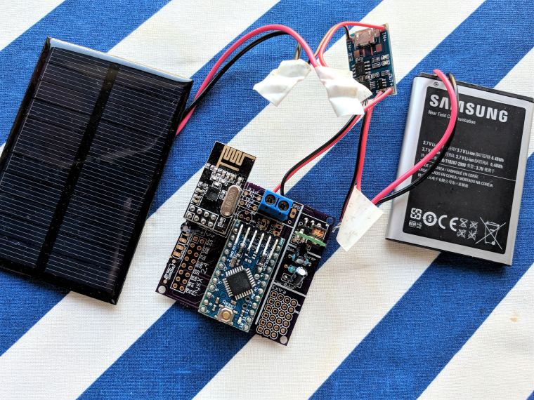
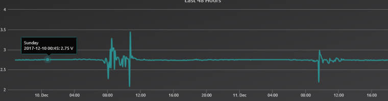
This is my setup. my battery reading is a constant 2.75v, this is not true the multi meter says ~4v
Thanks @sundberg84 and @gohan
I have used made the board for 3.3v set up as per the instruction. I have usd the output from tp4056 into the Battery connector of the board I have a step board from https://www.aliexpress.com/item/New-Electric-Unit-1-PC-NEW-DC-0-8-3-3V-to-DC-3-3V-StepUP/32724361266.html According to the specification given in the same link it is supposed to stabilize to 3.3v above 3v but the sensor reports something else back to the gateway.
I do not have an electronics background. I wend through the pdf files and order the parts and looks like I got the wrong resistor and capacitor or wrong part. Looks like I have to wait for an expert to comment let me know which resistor/capacitor goes where what part size. I would love to hear from someone ;)
IS it possible to use TP4056 (https://www.aliexpress.com/item/5-pcs-Micro-USB-5V-1A-18650-TP4056-Lithium-Battery-Charger-Module-Charging-Board-With-Protection/32728720869.html?spm=a2g0s.9042311.0.0.A0lkC7) this instead of using the step up booster?
Thanks!!
@Miroslav-Kadaně Thanks!!
@gohan I have a lot c version with me :)
@llegoff nice board!!! I think 🤔 I am going to build this. However just wondering if this will support rfm69hcw?
Thanks
@NeverDie Not sure if you are referring to me?
Does any one have links to dirty pcb or OSH Park? Thanks a lot
@Koresh Might be a dumb question I am planning to work on this board, where do I find the complete part list.
@petewill Thanks Pete!!! .. I shall give it a try.
Can't wait to try this baby!!!!
@Koresh waiting for the final PCB design + BOM so I can go shop :)
@doug Can't wait for you to release the BOM
@Ed1500 Thanks for you feedback. I have switched over to using W5100. However I have noticed that for some reason I am missing a data which is sent over nrf24. The gaps in the data are random and I can't seem to figure out why this is happening. BTW I am using domoticz on a pi to get the data. Initially I was using mysensor over usb to get the data and used to work fine. In order to get the update OTA I am trying to switch to ethernet Gateway and does not seem to work :(
//#define MY_DEBUG

#define MY_RADIO_NRF24
#define MY_GATEWAY_W5100

#define MY_SOFTSPI
#define MY_SOFT_SPI_SCK_PIN 14
#define MY_SOFT_SPI_MISO_PIN 16
#define MY_SOFT_SPI_MOSI_PIN 15

#define MY_RF24_CE_PIN 5
#define MY_RF24_CS_PIN 6


#define MY_IP_ADDRESS 192,168,0,66   // If this is disabled, DHCP is used to retrieve address
#define MY_PORT 5003

#define MY_MAC_ADDRESS 0xDE, 0xAD, 0xBE, 0xEF, 0xFE, 0xED


#define MY_DEFAULT_ERR_LED_PIN 7  // Error led pin
#define MY_DEFAULT_RX_LED_PIN  7  // Receive led pin
#define MY_DEFAULT_TX_LED_PIN  7  // Transmit led pin


#include <Ethernet.h>
#include <MySensors.h>


void setup(){
  delay(10000);
}

void loop(){
}
``I am not sure where I went wrong the below code hangs half way through. I am using ENC28J60
https://www.aliexpress.com/item/Mini-ENC28J60-Webserver-module-Ethernet-Shield-board-for-Arduino-Nano-v3-0/2037927977.html?spm=2114.40010208.4.8.mUp9p8
#ifndef config_h
#define config_h
#include <stdint.h>

/**********************************
   MySensors configuration
**********************************/
//#define MY_BAUD_RATE 9600
#define MY_DEBUG
//#define MY_BAUD_RATE 38400
//#define MY_BAUD_RATE 115200
//#define MY_NODE_ID 100

#define MY_RADIO_NRF24

// Enable gateway ethernet module type
#define MY_GATEWAY_ENC28J60
//#define MY_GATEWAY_W5100
// Enabled repeater feature for this node
//#define MY_REPEATER_FEATURE


// Enable Soft SPI for NRF radio (note different radio wiring is required)
// The ENC28J60 ethernet module seems to have a hard time co-operate with
// radio on the same spi bus.
#define MY_SOFTSPI
#define MY_SOFT_SPI_SCK_PIN 14
#define MY_SOFT_SPI_MISO_PIN 16
#define MY_SOFT_SPI_MOSI_PIN 15


// When ENC28J60 is connected we have to move CE/CSN pins for NRF radio
#ifndef MY_RF24_CE_PIN
#define MY_RF24_CE_PIN 5
#endif
#ifndef MY_RF24_CS_PIN
#define MY_RF24_CS_PIN 6
#endif


// Gateway IP address
#define MY_IP_ADDRESS 192,168,0,66

// The port to keep open on node server mode / or port to contact in client mode
#define MY_PORT 5003

// Controller ip address. Enables client mode (default is "server" mode).
// Also enable this if MY_USE_UDP is used and you want sensor data sent somewhere.
//#define MY_CONTROLLER_IP_ADDRESS 192, 168, 0, 55

// The MAC address can be anything you want but should be unique on your network.
// Newer boards have a MAC address printed on the underside of the PCB, which you can (optionally) use.
// Note that most of the Ardunio examples use  "DEAD BEEF FEED" for the MAC address.
#define MY_MAC_ADDRESS 0xDE, 0xAD, 0xBE, 0xEF, 0xFE, 0xFE

// Flash leds on rx/tx/err
//#define MY_LEDS_BLINKING_FEATURE
// Set blinking period
#define MY_DEFAULT_LED_BLINK_PERIOD 300

// Enable inclusion mode
#define MY_INCLUSION_MODE_FEATURE
// Enable Inclusion mode button on gateway
#define MY_INCLUSION_BUTTON_FEATURE
// Set inclusion mode duration (in seconds)
#define MY_INCLUSION_MODE_DURATION 60
// Digital pin used for inclusion mode button
#define MY_INCLUSION_MODE_BUTTON_PIN  3

#define MY_DEFAULT_ERR_LED_PIN 7  // Error led pin
#define MY_DEFAULT_RX_LED_PIN  8  // Receive led pin
#define MY_DEFAULT_TX_LED_PIN  9  // the PCB, on board LED


//#define MY_DISABLED_SERIAL


// Turn off debug if serial pins is used for other stuff
#ifdef MY_DISABLED_SERIAL
#undef MY_DEBUG
#endif


/**********************************
*  Gateway config
***********************************/

/**
 * @def MY_GATEWAY_MAX_RECEIVE_LENGTH
 * @brief Max buffersize needed for messages coming from controller.
 */
#ifndef MY_GATEWAY_MAX_RECEIVE_LENGTH
#define MY_GATEWAY_MAX_RECEIVE_LENGTH (100u)
#endif


/**
 * @def MY_GATEWAY_MAX_SEND_LENGTH
 * @brief Max buffer size when sending messages.
 */
#ifndef MY_GATEWAY_MAX_SEND_LENGTH
#define MY_GATEWAY_MAX_SEND_LENGTH (120u)
#endif

/**
 * @def MY_GATEWAY_MAX_CLIENTS
 * @brief Max number of parallel clients (sever mode).
 */
#ifndef MY_GATEWAY_MAX_CLIENTS
#define MY_GATEWAY_MAX_CLIENTS (1u)
#endif


/**
* @def MY_RX_MESSAGE_BUFFER_FEATURE
* @brief This enabled the receiving buffer feature.
*
* This feature is currently not supported for RFM69 and RS485, for RF24 MY_RF24_IRQ_PIN has to be defined.
*/
//#define MY_RX_MESSAGE_BUFFER_FEATURE

/**
 * @def MY_RX_MESSAGE_BUFFER_SIZE
 * @brief Declare the amount of incoming messages that can be buffered.
 */
#ifdef MY_RX_MESSAGE_BUFFER_FEATURE
#ifndef MY_RX_MESSAGE_BUFFER_SIZE
#define MY_RX_MESSAGE_BUFFER_SIZE  (20)
#endif
#endif

/**
 * @def MY_RF24_PA_LEVEL
 * @brief Default RF24 PA level. Override in sketch if needed.
 */
#ifndef MY_RF24_PA_LEVEL
#define MY_RF24_PA_LEVEL RF24_PA_MAX
#endif

/**
 * @def MY_RF24_CHANNEL
 * @brief RF channel for the sensor net, 0-125.
 * Frequence: 2400 Mhz - 2525 Mhz Channels: 126
 * http://www.mysensors.org/radio/nRF24L01Plus.pdf
 * 0 => 2400 Mhz (RF24 channel 1)
 * 1 => 2401 Mhz (RF24 channel 2)
 * 76 => 2476 Mhz (RF24 channel 77)
 * 83 => 2483 Mhz (RF24 channel 84)
 * 124 => 2524 Mhz (RF24 channel 125)
 * 125 => 2525 Mhz (RF24 channel 126)
 * In some countries there might be limitations, in Germany for example only the range 2400,0 - 2483,5 Mhz is allowed
 * http://www.bundesnetzagentur.de/SharedDocs/Downloads/DE/Sachgebiete/Telekommunikation/Unternehmen_Institutionen/Frequenzen/Allgemeinzuteilungen/2013_10_WLAN_2,4GHz_pdf.pdf
 */
#ifndef MY_RF24_CHANNEL
#define MY_RF24_CHANNEL  76
#endif

/**
 * @def MY_RF24_DATARATE
 * @brief RF24 datarate (RF24_250KBPS for 250kbs, RF24_1MBPS for 1Mbps or RF24_2MBPS for 2Mbps).
 */
#ifndef MY_RF24_DATARATE
#define MY_RF24_DATARATE RF24_250KBPS
#endif


#endif
#include "config.h"


#include <SPI.h>
#include <UIPEthernet.h>
#include <MySensors.h>

void setup() {
}
void loop() {
}
Output:
0;255;3;0;9;MCO:BGN:INIT GW,CP=RNNGA--,VER=2.1.1
0;255;3;0;9;TSM:INIT
0;255;3;0;9;TSF:WUR:MS=0
0;255;3;0;9;TSM:INIT:TSP OK
0;255;3;0;9;TSM:INIT:GW MODE
0;255;3;0;9;TSM:READY:ID=0,PAR=0,DIS=0
0;255;3;0;9;MCO:REG:NOT NEEDED
IP: 192.168.0.66
0;255;3;0;9;MCO:BGN:STP
0;255;3;0;9;MCO:BGN:INIT OK,TSP=1
0;255;3;0;9;Eth: connect
0;255;3;0;9;Eth: 0;0;3;0;2;
0;255;3;0;9;Eth: 0;0;3;0;2;Get Version
0;255;3;0;9;Eth: 0;0;3;0;18;PING
0;255;3;0;9;TSF:MSG:READ,1-1-255,s=255,c=3,t=7,pt=0,l=0,sg=0:
0;255;3;0;9;TSF:MSG:BC
0;255;3;0;9;TSF:MSG:FPAR REQ,ID=1
0;255;3;0;9;TSF:PNG:SEND,TO=0
0;255;3;0;9;TSF:CKU:OK
0;255;3;0;9;TSF:MSG:GWL OK
ketch uses 26,232 bytes (85%) of program storage space. Maximum is 30,720 bytes.
Global variables use 1,286 bytes (62%) of dynamic memory, leaving 762 bytes for local variables. Maximum is 2,048 bytes.
Pin 6,7, A1,A4