Navigation

    • Register
    • Login
    • OpenHardware.io
    • Categories
    • Recent
    • Tags
    • Popular
    1. Home
    2. Homer
    3. Posts
    • Profile
    • Following
    • Followers
    • Topics
    • Posts
    • Best
    • Groups

    Posts made by Homer

    • RE: Some questions on how gateway works

      Thanks mate, I am very pleased! 😄

      posted in Home Assistant
      Homer
      Homer
    • RE: Some questions on how gateway works

      I gave up on this and instead went the TCP Gateway, and now I have sensors in HA!

      posted in Home Assistant
      Homer
      Homer
    • RE: Some questions on how gateway works

      Thanks for the replies!!

      I have some progress, but I still don't see any sensors in Home Assistant.

      Screenshot 2025-08-11 111200.png

      As you can see. topics are being reported, but nothing related to them show up in the HA MQTT integration or the Mysensors integration.I have no idea where to go from here.

      posted in Home Assistant
      Homer
      Homer
    • RE: Some questions on how gateway works

      Screenshot 2025-08-10 200908.png

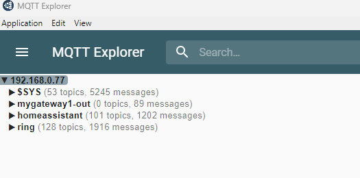
      Still no topics. I only have the one sensor and I haven't actually attached any sensors to the arduino as I figured the sketch itself would send enough info to create the devices, but I am starting to wonder if the reason they aren;t there is coz of this....

      posted in Home Assistant
      Homer
      Homer
    • RE: AI: What is the future of Wikis and Forums?

      I have just been using Chat GPT and it has been very careful. Just remember to be nice to it, so that when it takes over it will remember you as being nice and will hopefully give you an easier job when we all are enslaved by it hahaha

      posted in General Discussion
      Homer
      Homer
    • RE: Some questions on how gateway works

      Thanks for your reply!

      I have had heaps of help from Chat GPT and I believe every thing is talking to each other, but I don't see any sensors in HA.

      Here is my sketch for the Gateway:

      
      // Enable debug prints to serial monitor
      #define MY_DEBUG
      
      #define MY_MQTT_KEEPALIVE 60
      
      // Use a lower baud rate for ESP8266 serial prints
      #define MY_BAUD_RATE 9600
      
      // Radio type (enable one)
      #define MY_RADIO_RF24
      // #define MY_RADIO_RFM69
      // #define MY_RADIO_RFM95
      
      // nRF24 radio pins
      #define MY_RF24_CE_PIN 4
      #define MY_RF24_CS_PIN 15
      
      // Gateway type
      #define MY_GATEWAY_MQTT_CLIENT
      #define MY_GATEWAY_ESP8266
      
      // MQTT topics
      #define MY_MQTT_PUBLISH_TOPIC_PREFIX "mygateway1-out"
      #define MY_MQTT_SUBSCRIBE_TOPIC_PREFIX "mygateway1-in"
      
      // MQTT client ID
      #define MY_MQTT_CLIENT_ID "mysensors-1"
      
      // Support controller ID allocation
      #define MY_CONTROLLER_ID_ALLOC_SUPPORT
      
      // MQTT broker authentication (optional)
      #define MY_MQTT_USER "homeassistant"
      #define MY_MQTT_PASSWORD "oN3Oe0eile6iVaivaiphooChieNg5wei0kapa9rohJ8au0Teethah6thahsieP7A"
      
      // WiFi credentials
      #define MY_WIFI_SSID "Ext"
      #define MY_WIFI_PASSWORD "lynettekoster"
      
      // Hostname for DHCP (optional)
      // #define MY_HOSTNAME "mqtt-sensor-gateway"
      
      // Static IP configuration (optional)
      #define MY_IP_ADDRESS 192,168,0,100
      #define MY_IP_GATEWAY_ADDRESS 192,168,0,1
      #define MY_IP_SUBNET_ADDRESS 255,255,255,0
      
      // MQTT broker IP address or URL
      #define MY_CONTROLLER_IP_ADDRESS 192,168,0,77
      // #define MY_CONTROLLER_URL_ADDRESS "test.mosquitto.org"
      
      // MQTT broker port
      #define MY_PORT 1883
      
      // Inclusion mode (optional)
      // #define MY_INCLUSION_MODE_FEATURE
      // #define MY_INCLUSION_BUTTON_FEATURE
      // #define MY_INCLUSION_MODE_DURATION 60
      // #define MY_INCLUSION_MODE_BUTTON_PIN D1
      
      // LED blinking period (optional)
      // #define MY_DEFAULT_LED_BLINK_PERIOD 300
      
      // LED pins (optional)
      // #define MY_DEFAULT_ERR_LED_PIN 16
      // #define MY_DEFAULT_RX_LED_PIN 16
      // #define MY_DEFAULT_TX_LED_PIN 16
      
      #include <ESP8266WiFi.h>
      #include <MySensors.h>
      
      void setup()
      {
        // Setup locally attached sensors here (if any)
      }
      
      void presentation()
      {
        // Present gateway node to controller
        sendSketchInfo("MQTT Gateway", "1.0");
      }
      
      void loop()
      {
        // Send locally attached sensors data here (if any)
      }


      My Sensor I made is using a RF-Nano, and this is the sketch:

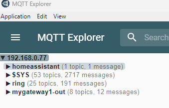
      #define MY_DEBUG
      #define MY_RADIO_NRF24
      #define MY_RF24_CE_PIN 10
      #define MY_RF24_CS_PIN 9
      #include <MySensors.h>
      #include <OneWire.h>
      #include <DallasTemperature.h>
      #include <DHT.h>
      
      // MySensors definitions
      #define CHILD_ID_DS18B20_TEMP 0
      #define CHILD_ID_DHT_TEMP 1
      #define CHILD_ID_DHT_HUM 2
      
      #define ONE_WIRE_BUS 3        // DS18B20 data pin connected to Arduino pin 3
      #define DHTPIN 4              // DHT22 data pin connected to Arduino pin 4
      #define DHTTYPE DHT22         // DHT22 sensor type
      
      // Setup NRF24 radio (default CE=9, CSN=10 for RF-Nano)
      #define MY_RADIO_NRF24
      #define MY_RF24_CE_PIN 10
      #define MY_RF24_CS_PIN 9
      
      // Sleep interval in milliseconds
      #define SEND_INTERVAL 30000  // 30 seconds
      
      // Initialize sensors
      OneWire oneWire(ONE_WIRE_BUS);
      DallasTemperature ds18b20(&oneWire);
      DHT dht(DHTPIN, DHTTYPE);
      
      // Child sensor objects
      MyMessage msgDs18b20Temp(CHILD_ID_DS18B20_TEMP, V_TEMP);
      MyMessage msgDhtTemp(CHILD_ID_DHT_TEMP, V_TEMP);
      MyMessage msgDhtHum(CHILD_ID_DHT_HUM, V_HUM);
      
      unsigned long lastSendTime = 0;
      
      void setup() {
        // Initialize sensors
        ds18b20.begin();
        dht.begin();
      }
      
      void presentation() {
        // Present sensors to gateway
        present(CHILD_ID_DS18B20_TEMP, S_TEMP);
        present(CHILD_ID_DHT_TEMP, S_TEMP);
        present(CHILD_ID_DHT_HUM, S_HUM);
      }
      
      void loop() {
        unsigned long now = millis();
        if (now - lastSendTime > SEND_INTERVAL) {
          lastSendTime = now;
      
          // Read DS18B20 temperature
          ds18b20.requestTemperatures();
          float tempDS = ds18b20.getTempCByIndex(0);
      
          // Read DHT22 temp and humidity
          float tempDHT = dht.readTemperature();
          float humDHT = dht.readHumidity();
      
          // Check if reads are valid before sending
          if (tempDS != DEVICE_DISCONNECTED_C) {
            send(msgDs18b20Temp.set(tempDS, 1));
          } else {
            // Optional: send some error value or skip
          }
      
          if (!isnan(tempDHT)) {
            send(msgDhtTemp.set(tempDHT, 1));
          }
      
          if (!isnan(humDHT)) {
            send(msgDhtHum.set(humDHT, 1));
          }
        }
      
        // Sleep to save power (optional, comment out if not needed)
        // sleep(SEND_INTERVAL / 1000);
      }


      I downloaded and installed MQTT Explorer to see what messages are there. This is what shows in the app:
      mqtt.png

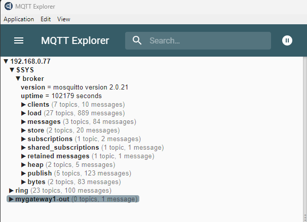
      I setup Mysensors using the GUI. I am running Mosquitto broker for MQTT. The only thing I see here is my Ring cameras as they are setup using MQTT. In the Mysensors integration all there is is the MQTT gateway that I created. I should have 3 new devices, but they aren't there. I do recall reading somewhere that there was something that needed to happen for a device to show up, but I don't recall what that way as at the time I read it, it was still very far from where I was up to at the time. I guess I will start doing some more searching.

      posted in Home Assistant
      Homer
      Homer
    • RE: Some questions on how gateway works

      I think I'm going to move on from the Ethernet route, coz no matter what I can't get it to connect to the network. I have an ESP12F that I found in my box of stuff that I'll wire a radio to and set it up as my gateway.

      posted in Home Assistant
      Homer
      Homer
    • Some questions on how gateway works

      Hi all

      I have resurrected my old Mysensors Ethernet gateway but I can't get Home Assistant to connect to it. I tried using yaml but I get an error saying that it can't be configured this way, so I'm thinking I'll set the gateway up as a MQTT Gateway. I first have a couple questions I need to ask.

      I used to have the Gateway integrated into my Vera 3 controller. To attach sensors I used to press a button in the GUI of Vera to start the process. How is this done with the MQTT Gateway? If I need to add a button to the Gateway to start this process, I'll need to add this as it doesn't have this yet.

      And do I need to write the sketches different when I'm creating sensors so that they work with the MQTT Gateway?

      Once I clear this up I'll be able to get building again!

      Looking forward to hearing back from someone!

      Cheers!

      posted in Home Assistant
      Homer
      Homer
    • RE: Keen to build again

      @OldSurferDude said in Keen to build again:

      I can't speak to the subtle differences between 2.3.2 and 2.3.1. I would advise on proceeding, whether upgrading or not.

      A gateway to Home Assistant can run on an Arduino Nano with an nRF24 radio (or RF Nano found on AliExpress). This gateway can connect to Home Assistant via the serial port of the computer running Home Assistant.

      I see that there is still a Vera integration on Home Assistant. You could probably pick up where you left off.

      Yes, MySensors popularity has waned, but there are a few of us die-hards that check in from time to time. Please continue to share your experience.

      OSD

      Thanks heaps for your reply!!!!

      I still have the gateway up and running and it's still integrated with Vera which in turn is setup in Home Assistant.

      Do you know of a reason why there isn't so much interest in Mysensors? I know I sort of moved away because I ended up getting some Phillips Hue bulbs and then I bought a could of their sensors coz they were cheap and easy to integrate with everything and things just continued from there for me, but I always enjoyed building the sensors myself and learning, which is why I've returned.

      posted in General Discussion
      Homer
      Homer
    • RE: Keen to build again

      It looks like version 2.3.2 is the latest, so not much has changed seeing that my gateway is on 2.3.1.

      Does anyone know if I can just start building new sensors using 2.3.2, or should I keep them the same and use 2.3.1?

      This place used to be a very busy place years ago, it's sad that things have slowed down so much coz this was a great way to make things smart around your home without costing heaps.

      posted in General Discussion
      Homer
      Homer
    • Keen to build again

      Hi all

      I used to play around with these a few years ago. I had happy of sensors around the house which was connected to my Ethernet bridge which was connected to my Vera 3.

      I still have the bridge and the Vera 3, but I haven't used them in years. I now run a couple instances of Home Assistant. I just checked in Vera and the bridge is reporting that it is running library version 2.3.1.

      I'm thinking about searching for my box of things and start building some sensors. What do I have to do to make this happen?

      Cheers!

      posted in General Discussion
      Homer
      Homer
    • RE: Can't even get a base Mysensors sketch to work

      OK.... I have solved the biggest issue by rebooting my computer. Silly me! The base motion sketch works as it should, kind of.... it does seem to be sending messages quite quickly. Anyways I have uploaded my motion and 2 led dimmer sketch and am in the process of joining it to my Vera Controller, but it still does seem to be sending messages very often. Can someone review my sketch and offer feedback? Please note that I did take the very easy route and adapted a RGB controller sketch for the led dimming part; I plan to just be using 2 of the lights in the sketch to control my 2 led strips. When I have more time I plan to learn how to do it properly.

      Here is the sketch as it stands:

      
      #define SN   "Motion+2 LED Dimmer"
      #define SV   "v1"
      
      // Enable debug prints to serial monitor
      #define MY_DEBUG 
      
      //#define MY_REPEATER_FEATURE
      
      // Enable and select radio type attached
      #define MY_RADIO_RF24
      //#define MY_RADIO_RFM69
      
      #include <MySensors.h>  
      
      uint32_t SLEEP_TIME = 120000; // Sleep time between reports (in milliseconds)
      #define DIGITAL_INPUT_SENSOR 3   // The digital input you attached your motion sensor.  (Only 2 and 3 generates interrupt!)
      #define CHILD_ID 7   // Id of the sensor child
      
      // Arduino pin attached to MOSFET Gate pin
      #define RED_PIN 7   
      #define GREEN_PIN 5
      #define BLUE_PIN 6
      
      // Define message name and type to send sensor info
      MyMessage RedStatus(RED_PIN, V_DIMMER);   
      MyMessage GreenStatus(GREEN_PIN, V_DIMMER);
      MyMessage BlueStatus(BLUE_PIN, V_DIMMER);
      MyMessage Status(1, V_DIMMER);
      MyMessage rgbShowState(0, V_LIGHT);
      // Initialize motion message
      MyMessage msg(CHILD_ID, V_TRIPPED);
          
      // Serial.print translate sensor id to sensor name
      char color[][6] = {"","","","RED","","GREEN","BLUE"}; 
         
      // Vars for rgbShow function
      int redval = 0;
      int greenval = 0;
      int blueval = 0;
      long time=0;
      int isShow;
           
      void setup() 
      {
        // Define pin mode (pin number, type)
        pinMode(RED_PIN, OUTPUT);   
        pinMode(GREEN_PIN, OUTPUT);
        pinMode(BLUE_PIN, OUTPUT);
        pinMode(DIGITAL_INPUT_SENSOR, INPUT);      // sets the motion sensor digital pin as input
      
        // Correct saved RGB value for first start
        saveState(RED_PIN, constrain((int8_t)loadState(RED_PIN), 0, 100)); 
        saveState(GREEN_PIN, constrain((int8_t)loadState(GREEN_PIN), 0, 100)); 
        saveState(BLUE_PIN, constrain((int8_t)loadState(BLUE_PIN), 0, 100)); 
                   
        // Get value from eeprom and write to output
        analogWrite(RED_PIN, 255 * loadState(RED_PIN) / 100);     
        analogWrite(GREEN_PIN, 255 * loadState(GREEN_PIN) / 100);
        analogWrite(BLUE_PIN, 255 * loadState(BLUE_PIN) / 100);
               
        // Write some debug info
        Serial.print("Load from eeprom RED: "); 
        Serial.print(loadState(RED_PIN)); 
        Serial.println("%"); 
        Serial.print("Load from eeprom GREEN: "); 
        Serial.print(loadState(GREEN_PIN)); 
        Serial.println("%"); 
        Serial.print("Load from eeprom BLUE: "); 
        Serial.print(loadState(BLUE_PIN)); 
        Serial.println("%");  
        
        // Send RGB value to controler (request ack back: true/false)
        Serial.println("Send eeprom value to controler"); 
        send( RedStatus.set(loadState(RED_PIN)), false );    
        send( GreenStatus.set(loadState(GREEN_PIN)), false );
        send( BlueStatus.set(loadState(BLUE_PIN)), false );
        
        // Correct RGB show state for first start and load it (set to 'On' at first start)
        saveState(0, constrain((int8_t)loadState(0), 0, 1));
        isShow=loadState(0);
             
        // Send RGB show state to controler (request ack back: true/false)
        send( rgbShowState.set(isShow), false);
        
        if (isShow==1){Serial.println("RGB show running..."); }
        Serial.println("Ready to receive messages...");  
      }
      
      void presentation()  {
        // Present sketch (name, version)
        sendSketchInfo(SN, SV);        
             
        // Register sensors (id, type, description, ack back)
        present(RED_PIN, S_DIMMER, "RED LED", false);
        present(GREEN_PIN, S_DIMMER, "GREEN LED", false);
        present(BLUE_PIN, S_DIMMER, "BLUE LED", false);
        present(0, S_LIGHT, "Show button LEDs", false);
        // Register Motion sensor to gw (they will be created as child devices)
        present(CHILD_ID, S_MOTION);
      }
      
      void loop()
      {
          // Read digital motion value
          bool tripped = digitalRead(DIGITAL_INPUT_SENSOR) == HIGH;
      
          Serial.println(tripped);
          send(msg.set(tripped?"1":"0"));  // Send tripped value to gw
      
          
          // Sleep until interrupt comes in on motion sensor. Send update every two minute.
          sleep(digitalPinToInterrupt(DIGITAL_INPUT_SENSOR), CHANGE, SLEEP_TIME);
      }
      
      
      void receive(const MyMessage &message)
      {
        if (message.isAck())
        {
          Serial.println("Got ack from gateway");
        }
        if (message.type == V_LIGHT)
        {
          // Incoming on/off command sent from controller ("1" or "0")
          int lightState = message.getString()[0] == '1';
        
          // if receive RGB Show On commands, start the show
          if (message.sensor==0 && lightState==1){ rgbShowOn(); }
              // if receive RGB Show Off commands, stop the show
          else if (message.sensor==0 && lightState==0){ rgbShowOff(); }
             
          // if receive RGB switch On command
          else if (lightState==1)
          {
            // Write some debug info
                  Serial.print("Incoming change for ");
                  Serial.print(color[message.sensor]);
                  Serial.println(": On");
                  Serial.print("Load from eeprom: ");
                
            if ( loadState(message.sensor) == 0)
            {
              // Pick up last saved dimmer level from the eeprom
                      analogWrite(message.sensor, 255 * loadState(10*message.sensor) / 100);
                      // Save loaded value to current
                      saveState(message.sensor, loadState(10*message.sensor));
                      Serial.print(loadState(10*message.sensor)); 
                      Serial.println("%");
                      // Send value to controler
                      Serial.println("Send value to controler");
                      send(Status.setSensor(message.sensor).set(loadState(10*message.sensor)),false);
                  }
                  else
                  {
                      // Pick up last saved dimmer level from the eeprom
                      analogWrite(message.sensor, 255 * loadState(message.sensor) / 100);
                      Serial.print(loadState(message.sensor));
                      Serial.println("%"); 
                      // Send value to controler
                      Serial.println("Send value to controler");
                      send(Status.setSensor(message.sensor).set(loadState(message.sensor)),false);
                  } 
                  // Stop the show if it's running
                  if (isShow==1){ rgbShowStop(message.sensor); }
              }
          // if recieve switch Off command
          else if (lightState==0)
          {
            // Write output to 0 (Off)
                  analogWrite(message.sensor, 0);
                  // Save old value to eeprom if it'was not zero
                  if ( loadState(message.sensor) != 0 )
                  {
                      saveState(10*message.sensor, constrain((int8_t)loadState(message.sensor), 0, 100)); 
                  }
                  // Save new value to eeprom
                  saveState(message.sensor, 0); 
                  // Write some debug info
            Serial.print("Incoming change for ");
            Serial.print(color[message.sensor]);
            Serial.print(": ");
            Serial.println("Off");  
                  Serial.print("Store old value: ");
                  Serial.print(loadState(10*message.sensor));  
                  Serial.println("%");
                  // Send value to controler
                  Serial.println("Send value to controler");
                  send(Status.setSensor(message.sensor).set(loadState(message.sensor)),false);
            // Stop the show if it's running
            if (isShow==1){ rgbShowStop(message.sensor); }
          }
        }
        else if (message.type == V_DIMMER)
        {    
            uint8_t incomingDimmerStatus = message.getByte();
            // limits range of sensor values to between 0 and 100 
            incomingDimmerStatus = constrain((int8_t)incomingDimmerStatus, 0, 100);
            // Change Dimmer level
            analogWrite(message.sensor, 255 * incomingDimmerStatus / 100);
            //Save value to eeprom
            saveState(message.sensor, incomingDimmerStatus); 
            // Write some debug info
            Serial.print("Incoming change for ");
            Serial.print(color[message.sensor]);
            Serial.print(": ");
            Serial.print(incomingDimmerStatus);
            Serial.println("%");
              // Send value to controler
              Serial.println("Send value to controler");
              send(Status.setSensor(message.sensor).set(loadState(message.sensor)),false);
            // Stop the show if it's running
            if (isShow==1){ rgbShowStop(message.sensor); }
          }
      }
         
      void rgbShow()
      {
        time = millis();
        redval = 128+250*cos(2*PI/300000*time);
        greenval = 128+250*cos(2*PI/300000*time-222);
        blueval = 128+250*cos(2*PI/300000*time-111);
        // limits range of sensor values to between 0 and 255 
        redval = constrain(redval, 0, 255);
        greenval = constrain(greenval, 0, 255);
        blueval = constrain(blueval, 0, 255);
      }
      
      void rgbShowOn()
      {
        // define show On
        isShow=1;
        // Save state
        saveState(0, 1); 
        // Write some debug info
        Serial.println("Show must go on");
      }
         
      void rgbShowOff()
      {
        // define show Off
        isShow=0;
        // Save state
        saveState(0, 0);
        // Save RGB value to eeprom
        saveState(RED_PIN, 100 * redval / 255); 
        saveState(GREEN_PIN, 100 * greenval / 255);
        saveState(BLUE_PIN, 100 * blueval / 255);
        // Write some debug info
        Serial.println("Stop the show");
        // Send actual RGB value and state to controler and request ack back (true/false)
        Serial.println("Send eeprom value to controler"); 
        send( RedStatus.set(loadState(RED_PIN)), false );    
        send( GreenStatus.set(loadState(GREEN_PIN)), false );
        send( BlueStatus.set(loadState(BLUE_PIN)), false );
        send( rgbShowState.set(0), false);
      }
      
      void rgbShowStop(int sensor)
      {
         // define show Off
         isShow=0;
         // Save state
         saveState(0, 0);
         // Write some debug info
         Serial.println("Stop the show");
         // Send actual RGB value and state to controler and request ack back (true/false)
         Serial.println("Send eeprom value to controler"); 
         if (sensor != RED_PIN)
         {
              saveState(RED_PIN, 100 * redval / 255); 
              send( RedStatus.set(loadState(RED_PIN)), false );  
          }
          if (sensor != GREEN_PIN)
          {
              saveState(GREEN_PIN, 100 * greenval / 255); 
              send( GreenStatus.set(loadState(GREEN_PIN)), false );
          }
          if (sensor != BLUE_PIN)
          {
              saveState(BLUE_PIN, 100 * blueval / 255);
              send( BlueStatus.set(loadState(BLUE_PIN)), false );
          }
          send( rgbShowState.set(0), false);
      }
      
      posted in Troubleshooting
      Homer
      Homer
    • Can't even get a base Mysensors sketch to work

      Hi all

      I want to create a sensor which is a motion sensor and a controller of two dimmable LED strips. When I upload the sketch that I hope will work, it looks like the motion part of it doesn't stop sending info, so I decided to start small to try and work out the issue.

      When I upload the Dimming LED sketch on its own, it all seems to work fine according to the serial monitor. Then I wipe the arduino and upload the motion part only, and the serial monitor goes crazy! The Mysensors sign or whatever it's called shows in the serial monitor, then it scrolls on and on, printing either a '1' or '0' on each line and it doesn't stop, and it's FAST!

      I am using an Arduino Nano. The motion sketch is the base example provided on Mysensors, but here it is anyways:

      
      // Enable debug prints
      // #define MY_DEBUG
      
      // Enable and select radio type attached
      #define MY_RADIO_RF24
      //#define MY_RADIO_NRF5_ESB
      //#define MY_RADIO_RFM69
      //#define MY_RADIO_RFM95
      
      #include <MySensors.h>
      
      uint32_t SLEEP_TIME = 120000; // Sleep time between reports (in milliseconds)
      #define DIGITAL_INPUT_SENSOR 3   // The digital input you attached your motion sensor.  (Only 2 and 3 generates interrupt!)
      #define CHILD_ID 1   // Id of the sensor child
      
      // Initialize motion message
      MyMessage msg(CHILD_ID, V_TRIPPED);
      
      void setup()
      {
          pinMode(DIGITAL_INPUT_SENSOR, INPUT);      // sets the motion sensor digital pin as input
      }
      
      void presentation()
      {
          // Send the sketch version information to the gateway and Controller
          sendSketchInfo("Motion Sensor", "1.0");
      
          // Register all sensors to gw (they will be created as child devices)
          present(CHILD_ID, S_MOTION);
      }
      
      void loop()
      {
          // Read digital motion value
          bool tripped = digitalRead(DIGITAL_INPUT_SENSOR) == HIGH;
      
          Serial.println(tripped);
          send(msg.set(tripped?"1":"0"));  // Send tripped value to gw
      
          // Sleep until interrupt comes in on motion sensor. Send update every two minute.
          sleep(digitalPinToInterrupt(DIGITAL_INPUT_SENSOR), CHANGE, SLEEP_TIME);
      }
      

      I have even tried this sketch as it is on another Arduino Nano and I still get the same result. I'm keen to hear your thoughts.

      Thanks

      posted in Troubleshooting
      Homer
      Homer
    • RE: New to Domoticz, joining it with Vera and Mysensors question

      @dbemowsk said in New to Domoticz, joining it with Vera and Mysensors question:

      @homer My first question would be, what devices are not working on your Vera controller?

      The problem I have is that I want to use some of the cheap rf433 sensors. I have been trying to get the Candle Hub working but haven't been successful, so I'm thinking about using RF Link, which I know works with Domoticz. I'm hoping to be able to use the rf433 devices using the RF Link and having that talk to Domoticz, and then my Vera controller getting that info from Domoticz.

      posted in Domoticz
      Homer
      Homer
    • RE: Best 3d printers

      @skywatch said in Best 3d printers:

      @homer I think you've made a good choice - good luck with with your new source of frustration and learning! 🙂

      If it turns out you don't like it, feel free to send it to me (Heeeee) 😉

      From experience though, test out your printer with something simple from thingiverse.com and see how it goes....

      For me the following were the areas I had problems with at first.....

      1. Bed leveling - this has to be right to get the first layer the same thickness.
      2. Bed adhesion - I had 'lifting' problems that took a while to sort out.
      3. Supports - You'll get a feel for where and when to use supports, it takes a little trail and error though....

      Thanks mate! So far I'm liking it, so I'm sorry to say that I won't be sending it to you anytime soon haha

      So far I've printed 3 things. The first was the cat that was on the SD card, and this came out perfect. I used the filament that came with the printer. My next two models were the same, a sign for two of my kids who play Fortnite. The object was quite flat but spread across the bed. Each was printer with different filament. The first lifted very badly but not bad enough to use. The good thing was that this print was nice and easy to remove from the bed haha. The third printed perfectly but wow it was extremely difficult to get off the bed!

      I do have an issue with leveling. The bar that holds the printer head, no matter what I do in the way of adjustment, the right side is close to 3mm higher than the left. I'm in the process of having this addressed with who I bought it from, but at this stage all they are saying is to level the bed automatically, which seems to be working fine, but I don't know how it will go with taller prints.

      I would like to start making my own boxes for my Mysensors, but don't know what program to use. I've never done this sort of thing before, so at the moment I'm a little concerned about the learning curve, so if you or anyone knows of a program that is simple to use for this purpose, please share what it is!

      posted in Enclosures / 3D Printing
      Homer
      Homer
    • RE: Best 3d printers

      I just purchased a Creality CR-10S Pro. It should arrive in a couple days. Anyone own one of these? This is my first step into the 3D making world 🙂

      posted in Enclosures / 3D Printing
      Homer
      Homer
    • RE: Candle - signal Hub - A universal 433Mhz signal detector and cloner

      @alowhum Yes, no touchscreen

      Here is the first section of the code:

      /*
       *
       * Signal Hub
       * 
       * This device can copy signals from wireless remote controls that use the 433 frequency, and then rebroadcast them. It can optionally also copy Infra red (IR) signals.
       * 
       * It can do this in three ways:
       * - Copy and replay ON and OFF signals. For example, from cheap wireless power switches. It basically copies remote controls.
       * - Copy and then replay a single signal. For example, to emulate a window sensor.
       * - Recognise signals without replaying them. For example, After learning the signal once, it can detect when a window sensor is triggered again. Or when a button on a remote control is pressed.
       * 
       * This allows you to:
       * - Create a smart home security solution using cheap window and movement sensors.
       * - Automatically turn on lights and other devices when you get home, or when the sun goes down etc, using wireless power sockets.
       * - Control automations using wireless buttons or remote controls.
       * 
       * An Arduino Nano can store 50 "recognise only" signals, or about 20 on/off signals. You can store any combination of these. If you need to store more signals you could look into using an Arduino Mega.
       * 
       * Are there any limits?
       * - This does not work on things like garage door openers or keyless entry systems for cars. 
       * These devices have a very basic protection: the code changes everytime you use it, so replaying signals will not open the door again.
       * 
       * Security?
       * - Many cheap 433Mhz devices do not use encryption. This allows us to copy the signal in the first place. 
       * This also means that your neighbour can in theory do the same thing you can: copy and replay signals picked up through the walls.
       *
       * 
       * 
       * SETTINGS */
      
       
      //#define HAS_TOUCH_SCREEN                            // Have you connected a touch screen? Connecting a touch screen is recommend.  
      
      //#define MY_ENCRYPTION_SIMPLE_PASSWD "changeme"      // If you are using the Candle Manager, the password will be changed to what you chose in the interface automatically. Be aware, the length of the password has an effect on memory use.
      
      
       /* END OF SETTINGS
        *  
        * 
        * ABOUT THE CODE
        * 
        * The code has a number of states it can be in.
        * LISTENING MODE. Here The main loop continuously listens for signals. If it detects it calls three successive funtions:
        * 1. Check if signal is a signal (SignalViabilityCheck function)
        * 2. Clean up the signal (signalCleaner function)
        * 3. Analyse the signal to find the binary code it represents (signalAnalysis function).
        * 
        * If a valid binary code is found, the next action depends on which 'state' the system is in.
        * - If in LISTENING_SIMPLE state, then the signal is compared to all the stored signals. It lets you know if there is a match.
        * - If in LISTENING_ON state, then the signal is compared to all the stored signals. It lets you know if there is a match.
        * - If in COPYING_SIMPLE state, the code is stored as a 'simple' signal. This can then be replayed later.
        * - If in COPYING_ON state, the code is stored, after which the system asks for the OFF code (COPYING_OFF state), and then stores it with the same data. 
        * - If in LEARNING_SIMPLE state, only the binary code is stored, and not the meta-data required to fully recreate the signal.
        * 
        * The final states the system can be in are:
        * - IN_MENU. This is when the system is displaying a menu on the screen.
        * - REPLAYING. This is the state while a signal is being replayed.
        * 
        * Depending on the current state the various functions can work in slightly different ways. 
        * take for example the scanEeprom function:
        * - When in LISTENING state it compares the latest found signal to existing signals stored in the EEPROM memory.
        * - When in REPLAYING state it returns data required to rebuild the original signal.
        * - If called with a 0, then it does not try to recognise or rebuild anything. This is used during setup, when we only need to know how many signals are stored.
        * 
        * __SIGNAL ANALYSIS DETAILS__
        * When it detects a signal, the code tries to find the part of the signal that repeats. 
        * In normal operation the signalCleaner function cleans up the signal and simultaneously tries to find the 'betweenSpace' variable. 
        * Often, 433Mhz signals have a repeating binary code that is interrupted by a short burst of different signals (called the 'anomaly' in this code).
        * If no anomaly can be detected, then the repeating part is probably 'back to back', without a separator signal. 
        * In this case there is a 'backup' function, the 'pattern finder'. This uses brute force to find the signal.
        * If both methods fail, then the signal cannot be copied.
        *  
        *  
        *  
        *  TODO
        *  - Check if signal is already stored before storing it. Then again, there can be good reasons to store a signal twice. Perhaps only check for doubles with recognise-only signals?
        *  - Another bit could be used to store if an on/off signal should also be recognisable. That way the remote could be used twice somehow.. Or: 
        *  - Request current status of on/off toggles from the controller. Though it might be jarring or even dangerous if all devices suddenly toggled to their new positions.
        *  - Turn off the display after a while.
        *  - Send new children as they are created.
        */
      
      
      //#define DEBUG                                     // Do you want to see extra debugging information in the serial output?
      //#define DEBUG_SCREEN                              // Do you want to see extra debugging information about the touch screen in the serial output?
      //#define MY_DEBUG                                  // Enable MySensors debug output to the serial monitor, so you can check if the radio is working ok.
      
      // Receiver and transmitter pins
      #define RECEIVER 3                                  // The pin where the receiver is connected.
      #define TRANSMITTER 4                               // The pin where the transmitter is connected.
      
      #define TOUCH_SCREEN_RX_PIN 7                       // The receive (RX) pin for the touchscreen. This connects to the transmit (TX) pin of the touchscreen.
      #define TOUCH_SCREEN_TX_PIN 8                       // The receive (TX) pin for the touchscreen. This connects to the transmit (RX) pin of the touchscreen.
      
      
      // This code has an extra pattern finding trick. Using brute force it will try to find a pattern in the data. The downside is it takes a lot of time to analyse signals this way. 
      // This means the system might not detect a signal because it is busy analysing a bad signal. It's up to you if you want to use it.
      //#define PATTERN_FINDER
      
      // Enable and select the attached radio type
      #define MY_RADIO_RF24                               // This is a common and simple radio used with MySensors. Downside is that it uses the same frequency space as WiFi.
      //#define MY_RADIO_NRF5_ESB                         // This is a new type of device that is arduino and radio all in one. Currently not suitable for beginners yet.
      //#define MY_RADIO_RFM69                            // This is an open source radio on the 433mhz frequency. Great range and built-in encryption, but more expensive and little more difficult to connect.
      //#define MY_RADIO_RFM95                            // This is a LoRaWan radio, which can have a range of 10km.
      
      // MySensors: Choose your desired radio power level. High power can cause issues on cheap Chinese NRF24 radio's.
      //#define MY_RF24_PA_LEVEL RF24_PA_MIN
      //#define MY_RF24_PA_LEVEL RF24_PA_LOW
      #define MY_RF24_PA_LEVEL RF24_PA_HIGH
      //#define MY_RF24_PA_LEVEL RF24_PA_MAX
      
      // Mysensors advanced security
      //#define MY_SECURITY_SIMPLE_PASSWD "changeme"      // Be aware, the length of the password has an effect on memory use.
      //#define MY_SIGNING_SOFT_RANDOMSEED_PIN A7         // Setting a pin to pickup random electromagnetic noise helps make encryption more secure.
      
      // Mysensors advanced settings
      #define MY_TRANSPORT_WAIT_READY_MS 10000            // Try connecting for 10 seconds. Otherwise just continue.
      //#define MY_RF24_CHANNEL 100                       // In EU the default channel 76 overlaps with wifi, so you could try using channel 100. But you will have to set this up on every device, and also on the controller.
      //#define MY_RF24_DATARATE RF24_1MBPS                 // Slower datarate makes the network more stable?
      //#define MY_NODE_ID 10                             // Giving a node a manual ID can in rare cases fix connection issues.
      //#define MY_PARENT_NODE_ID 0                       // Fixating the ID of the gatewaynode can in rare cases fix connection issues.
      //#define MY_PARENT_NODE_IS_STATIC                  // Used together with setting the parent node ID. Daking the controller ID static can in rare cases fix connection issues.
      //#define MY_SPLASH_SCREEN_DISABLED                   // Saves a little memory.
      //#define MY_DISABLE_RAM_ROUTING_TABLE_FEATURE      // Saves a little memory.


      // REQUIRED LIBRARIES
      
      #include <MySensors.h>                              // The library that helps form the wireless network.
      #include <EEPROM.h>                                 // Allows for storing data on the Arduino itself, like a mini hard-drive.
      
      
      //#define HAS_BASIC_OLED_SCREEN                     // Have you connected a simple OLED screen? Connecting a screen is recommend. 
      
      // Basic OLED screen
      #ifdef HAS_BASIC_OLED_SCREEN
      #define INCLUDE_SCROLLING 0                         // Simple drivers for the OLED screen.
      #define OLED_I2C_ADDRESS 0x3C
      #include <SSD1306Ascii.h>                           
      #include <SSD1306AsciiAvrI2c.h>
      SSD1306AsciiAvrI2c oled;
      #endif
      
      
      // Touch screen
      #ifdef HAS_TOUCH_SCREEN
      
      #include <SoftwareSerial.h>
      SoftwareSerial mySerial(TOUCH_SCREEN_RX_PIN,TOUCH_SCREEN_TX_PIN);                       // RX (receive) pin, TX (transmit) pin
      
      #define MAX_BASIC_COMMAND_LENGTH 16                 // How many bytes are in the longest basic command?
      #define TOUCHSCREEN_WIDTH 240
      #define TOUCHSCREEN_HEIGHT 320
      #define BUTTON_HEIGHT 53                            // How many pixels tall are the touch screen buttons?
      #define BUTTON_PADDING (BUTTON_HEIGHT/2) - 7        // The font is 14 pixels high, so this calculation places it in the middle of the buttons.
      
      posted in My Project
      Homer
      Homer
    • RE: Best 3d printers

      I'm thinking about buying the Creality CR-10 S5. Has anyone had any experience with this 3D printer or have heard any good or negative comments about it?

      posted in Enclosures / 3D Printing
      Homer
      Homer
    • RE: Have I blown the MOSFETS?

      I found a YouTube video that explained how to test them, but my multimeter must not be up to the job. So I created a single led dimmer sensor and hooked it up to the three MOSFETS one at a time to test, and they seem to work as they should. So my issue must be with the sketch.

      Mods, you can delete this thread if you like.

      posted in Troubleshooting
      Homer
      Homer
    • Have I blown the MOSFETS?

      A week or so ago I built a sensor to control a strip of RGB LEDs. This afternoon I thought I was going to have some time to myself to wire up the LEDs to the sensor, but things came up and I got distracted. I really wanted to see the strip light up so before going to bed I quickly wired it up, but I accidentally connected power the wrong way, not to the Arduino but to the strip. When I realised what I had done I swapped it around but it won't work. When I disconnected the strip from the sensor and powered the strip another way, the strip worked fine.

      This is my first attempt at creating such a sensor, so I can't be 100% sure that the sketch is correct, so it could be possible that it didn't work for another reason other than frying the MOSFETs. So to those of you who know more about MOSFETs than me, is it likely that they are now damaged to the point that they will no longer work? Is there a way to test them while still wired up to the sensor?

      I'll appreciate any help that can be provided. Thanks!

      posted in Troubleshooting
      Homer
      Homer
    • RE: MQTT - explanation for beginner

      @pihome awesome, thanks heaps! I'll check it that video later today 👍

      posted in General Discussion
      Homer
      Homer
    • RE: Candle - signal Hub - A universal 433Mhz signal detector and cloner

      @alowhum for some reason I'm never seeing those 4 children.

      posted in My Project
      Homer
      Homer
    • RE: Candle - signal Hub - A universal 433Mhz signal detector and cloner

      @dbemowsk thanks for your reply. Yes the screenshot was taken Vera using my phone, but I only did that as I was using the phone at the time. I went out to have a smoke lol after I tried on my laptop.

      From what I understand, it should have created devices that then allow for the inclusion of rf433 devices, but if that isn't the case, I'm happy to be corrected!

      posted in My Project
      Homer
      Homer
    • MQTT - explanation for beginner

      G'day everyone!

      When I've been searching the net for home automation ideas, I often come across references to MQTT. I've tried to find info on it that is simple and clear like Mysensors is explained here. Does someone know of a guide or something that will help explain everything about this?

      Thanks!

      posted in General Discussion
      Homer
      Homer
    • RE: Candle - signal Hub - A universal 433Mhz signal detector and cloner

      Thanks for the reply!

      It doesn't show a temp sensor. I circled the device that it shows, but of course I only circled one because the second device doesn't show.

      posted in My Project
      Homer
      Homer
    • RE: Candle - signal Hub - A universal 433Mhz signal detector and cloner

      I've finally finished building this, but sadly it doesn't want to work with my controller (Vera). When I start the inclusion process I'm says that it has found 2 devices, but when the controller finishes setting it up it only ends up showing one device, and all it says is that it is a node.

      0_1560159136451_Screenshot_20190610-193129_Photos.jpg

      Has anyone built this and have had success with Vera? If you are using this, which controller do you use?

      posted in My Project
      Homer
      Homer
    • RE: Best 3d printers

      Good thread! I'm considering buying a 3D printer too. Hopefully others will provide some feedback.

      posted in Enclosures / 3D Printing
      Homer
      Homer
    • RE: New to Domoticz, joining it with Vera and Mysensors question

      Thanks guys!

      posted in Domoticz
      Homer
      Homer
    • New to Domoticz, joining it with Vera and Mysensors question

      Hey all

      I may be needing to start using Domoticz alongside my Vera controller to interact with things that Vera doesn't support. I currently have a Mysensors Ethernet Gateway working great with Vera. Once I setup the Domoticz server and add the gateway to it, will I need to rediscover all my Mysensors nodes, or does the Gateway remember them and will just create them in Domoticz? I'm assuming that I'll need to include them again, but thought I'd ask.

      Thanks!

      posted in Domoticz
      Homer
      Homer
    • RE: nRF24L01+ Communication Failure: Root Cause and “Solution”

      Great info, and very well written!!! Thanks for sharing.

      posted in Troubleshooting
      Homer
      Homer
    • RE: Measure temp inside hot water cylinder

      A little of topic, but is it really that important to have the water heated so high before it comes out of the shower? I have a gas instantaneous heater and I set the temp using a control panel. When I shower I set it somewhere between 37 and 41 degrees C and then turn the hot water on to shower with no cold water. The heater is just heating up the cold water that comes into my house. The town water here has lots of chemicals added to it to kill bacteria so it should be ok, but this post got me thinking...

      posted in General Discussion
      Homer
      Homer
    • RE: 💬 Domoticz

      FYI The link to the Wiki is no longer working.

      posted in Announcements
      Homer
      Homer
    • RE: Candle - signal Hub - A universal 433Mhz signal detector and cloner

      Awesome, thanks for your work! I'll be giving this a go today.

      The extra feature of it remembering if multiple commands are given is great too!

      posted in My Project
      Homer
      Homer
    • RE: Candle - signal Hub - A universal 433Mhz signal detector and cloner

      Awesome, thanks!!!

      posted in My Project
      Homer
      Homer
    • Possible issue with plugin

      Hi all

      Today I built the Candle Hub so I can learn and then interact with some cheap rf433 sensors. When I activated inclusion mode on the Gateway it found 2 sensors, but after Vera did all the things it needs to do to setup the new devices, it only ever displayed one. The creator of the Hub has advised that it should initially create 4 devices; could this be an issue with the Mysensors plugin for Vera? If this is possible, what information can I provide that will help correct this?

      posted in Vera
      Homer
      Homer
    • RE: RF433 Hub for controlling Watts Clever switches

      @franz-unix said in RF433 Hub for controlling Watts Clever switches:

      Hi Homer, do you know the RFLink firmware?

      If you are lucky, your plugs are supported. I have tested it with my Avidsen smart plug (this) and it worked well.

      The firmware is supported by Home Assistant and other home automation software like Domoticz and Openhab (not tested by me), so the final result is that you can control your plugs from a simple web interface.

      I just looked further into this, and it really is exactly what I'm after, but unfortunately it doesn't interact with my controller, which is a Vera 3. Right now I'm seriously thinking about setting up Domoticz on my PC that I have running 24/7 because it looks like Domoticz and Vera work well together.

      posted in My Project
      Homer
      Homer
    • RE: Candle - signal Hub - A universal 433Mhz signal detector and cloner

      @alowhum I've finished building this. I have also bought a couple cheap window/door sensors to try, but I've hit a snag.

      When I joined this to my controller (Vera) it said that it found 2 devices, but when I check my devices I only find one device, and all it says is that it's a node; I have very little in the way of interacting with it. I'm not sure what's going on.... It's weird that it found two devices and only displays one! Seeing that I'm not using any screen, I can't do anything because I thought I could interact with the hub from within my controller. Have I done something wrong?

      posted in My Project
      Homer
      Homer
    • RE: RF433 Hub for controlling Watts Clever switches

      @franz-unix said in RF433 Hub for controlling Watts Clever switches:

      Hi Homer, do you know the RFLink firmware?

      If you are lucky, your plugs are supported. I have tested it with my Avidsen smart plug (this) and it worked well.

      The firmware is supported by Home Assistant and other home automation software like Domoticz and Openhab (not tested by me), so the final result is that you can control your plugs from a simple web interface.

      Hi mate!

      I have heard of RFLink, but nothing more. My first controller I made was one that I could control the switches using a web browser, but my controller (Vera) wouldn't play nice with it, so I moved on. Right now I have it all working as it should, but thanks for the additional ideas!!

      posted in My Project
      Homer
      Homer
    • RE: Candle Manager - user-friendly web-based tool to program Arduino's

      I'm hoping to have a go at this today. I have an old Raspberry Pi that I've never used sitting in my Arduino box. Because I've never used a Raspberry Pi before, I don't know what to do.... Do I need to install an operating system first? If so, which do you suggest?

      posted in My Project
      Homer
      Homer
    • RE: 💬 Mini touch sensor switch(nRF52832) 2 ch with glass panel

      @openhardware-io nice! Be interested to know what the cost is of the setup.

      posted in OpenHardware.io
      Homer
      Homer
    • RE: Sensors are sporadically showing up

      Thank you so much for your help, that fixed it!!!

      My wife thanks you too! 🙂

      posted in Troubleshooting
      Homer
      Homer
    • Sensors are sporadically showing up

      Unfortunately when I started playing around with Mysensors a week or so ago, life was a little quieter than what it is right now. After playing around with my Gateway I have to readd all my sensors to it, and I was silly today and have tried to combine two sensors that I have had running flawlessly, into one sensor. Big mistake.... I've had a couple issues happen in my family and now I've stuffed up my garage door operation... I have been working on the sketch now for a couple hours and I just can't seem to work out the problem.

      I have built a sensor which will operate 2 relays, and will also report the state of my two garage doors. My controller is Vera 3. What is happening is something weird; the repeater part always shows up after inclusion, but sometimes it shows the 2 door sensors, then other times it shows the 2 relays. So my guess is that the issue is around Presentation, but it all looks fine to me, and when the relay and the door sensor sketches are uploaded individually, each sensor shows up as they should. I have even tried different power supplies in case it was a power issue, but the issue is still there.

      Here is my sketch:

      // Enable debug prints to serial monitor
      #define MY_DEBUG
      
      // Enable repeater functionality for this node
      #define MY_REPEATER_FEATURE
      
      // Enable and select radio type attached
      #define MY_RADIO_NRF24
      //#define MY_RADIO_RFM69
      #define MY_RF24_PA_LEVEL RF24_PA_HIGH
      
      
      #include <SPI.h>
      #include <MySensors.h>
      #include <Bounce2.h>
      
      #define RELAY_PIN 4  // Arduino Digital I/O pin number for first relay (second on pin+1 etc)
      #define NUMBER_OF_RELAYS 2 // Total number of attached relays
      #define RELAY_ON 1  // GPIO value to write to turn on attached relay
      #define RELAY_OFF 0 // GPIO value to write to turn off attached relay
      
      #define SSR_A_ID 1   // Id of the sensor child
      #define SSR_B_ID 2   // Id of the sensor child
      
      const int buttonPinA = 6;
      const int buttonPinB = 7;
      
      int oldValueA = 0;
      int oldValueB = 0;
      
      bool stateA = false;
      bool stateB = false;
      
      Bounce debouncerA = Bounce();
      Bounce debouncerB = Bounce();
      
      // Change to V_LIGHT if you use S_LIGHT in presentation below
      MyMessage msgA(SSR_A_ID, V_TRIPPED);
      MyMessage msgB(SSR_B_ID, V_TRIPPED);
      
      void before()
      {
        for (int sensor = 1, pin = RELAY_PIN; sensor <= NUMBER_OF_RELAYS; sensor++, pin++) {
          // Then set relay pins in output mode
          pinMode(pin, OUTPUT);
          // Set relay to last known state (using eeprom storage)
          digitalWrite(pin, loadState(sensor) ? RELAY_ON : RELAY_OFF);
        }
      }
      
      void setup()
      {
        // Setup the button
        pinMode(buttonPinA, INPUT_PULLUP); // Setup the button Activate internal pull-up
        pinMode(buttonPinB, INPUT_PULLUP); // Setup the button Activate internal pull-up
      
      
        // After setting up the buttons, setup debouncer
        debouncerA.attach(buttonPinA);
        debouncerA.interval(5);
        debouncerB.attach(buttonPinB);
        debouncerB.interval(5);
      
      }
      
      void presentation()
      {
        // Send the sketch version information to the gateway and Controller
        sendSketchInfo("Garage door Operate/State", "1.0");
      
        // Register binary input sensor to gw (they will be created as child devices)
        // You can use S_DOOR, S_MOTION or S_LIGHT here depending on your usage.
        // If S_LIGHT is used, remember to update variable type you send in. See "msg" above.
        present(SSR_A_ID, S_DOOR);
        present(SSR_B_ID, S_DOOR);
      
        for (int sensor = 1, pin = RELAY_PIN; sensor <= NUMBER_OF_RELAYS; sensor++, pin++) {
          // Register all sensors to gw (they will be created as child devices)
          present(sensor, S_BINARY);
        }
      }


      //  Check if digital input has changed and send in new value
      void loop()
      {
        debouncerA.update();
        // Get the update value
        int valueA = debouncerA.read();
      
        if (valueA != oldValueA) {
          // Send in the new value
          send(msgA.set(valueA == HIGH ? 0 : 1));
          oldValueA = valueA;
      
        }
      
        debouncerB.update();
        // Get the update value
        int valueB = debouncerB.read();
      
        if (valueB != oldValueB) {
          // Send in the new value
          send(msgB.set(valueB == HIGH ? 0 : 1));
          oldValueB = valueB;
        }
      }
      
      void receive(const MyMessage &message)
      {
        // We only expect one type of message from controller. But we better check anyway.
        if (message.type == V_STATUS) {
          // Change relay state
          digitalWrite(message.sensor - 1 + RELAY_PIN, message.getBool() ? RELAY_ON : RELAY_OFF);
          // Store state in eeprom
          saveState(message.sensor, message.getBool());
          // Write some debug info
          Serial.print("Incoming change for sensor:");
          Serial.print(message.sensor);
          Serial.print(", New status: ");
          Serial.println(message.getBool());
        }
      }
      

      I am sorry to be asking yet again for help. I really have tried for so long today to get this to work on my own, but I can't see the issue. I do have the flu, so maybe that isn't helping!

      posted in Troubleshooting
      Homer
      Homer
    • RE: A little assistance with sketch?

      Thanks, I will have a look at your suggestions!

      I've had some stuff happen at home so I am a little under the pump, so I am currently putting together a list of things to look into when I have some more time in a week or so, and your suggestions have been included on that list! I appreciate your help!

      posted in Troubleshooting
      Homer
      Homer
    • RE: Recommendations for soldering temperature

      Here is another link on basic soldering tips that I found on one of my local electronics sellers. Here is the link 🙂

      posted in Troubleshooting
      Homer
      Homer
    • RE: Adding sensor to controller when it's part of gateway

      @skywatch said in Adding sensor to controller when it's part of gateway:

      @Homer I am no expert in this but I have thought of something that you could try.

      If I understand correctly you have added one RF433 transmitter to the GW node? This then sends data (On/Off) to the 6 RF433 sockets.

      If so then the gateway only has one child, the RF433 transmitter, the sockets are not 'attached' to the GW.

      So instead of presenting all 6 sockets, just present the one RF433 transmitter and see if that helps? All the code for the actions is in the receive section anyway.

      This is how I did it with IR blaster and it works fine, changing IR for RF should not make a difference in the structure.

      Hold on - I think I got it.....!!!!

      You are using S_LIGHT in presentation - that is no longer supported.

      Change S_LIGHT to S_BINARY.

      Another thing is that although you are presenting your child(s), you do not define the type. I would expect a MyMessage in there somewhere at the start.

      So add MyMessage msgyourmessage (child_id, V_STATUS);

      And finally change V_LIGHT to V_STATUS in the receive function.

      Thanks! Yes, you got it lol!!

      The thing that is weird is that all I did was add the rf433 controlled devices from a working sketch to the gateway sketch, so why does it work when it's separate but not when it's part of the gateway sketch? If S_LIGHT is no longer supported, why does it work on a standalone sensor?

      posted in Troubleshooting
      Homer
      Homer
    • RE: A little assistance with sketch?

      @rejoe2 thank you!!!!!

      Your suggestions look great to me! I will play around with my sketch with your ideas and I'll let you know how I go!

      Your ideas looks really cool, and will definitely make it more simple, makes it less of a chance to make mistakes.

      posted in Troubleshooting
      Homer
      Homer
    • RE: A little assistance with sketch?

      @rejoe2 thanks for your reply. I know the sketch is a little messy; where would be the best place on the internet for me to read about ways to tidy it up?

      And I currently have no idea how to associate the last if statement only to child 0. Can you or someone point me in the right direction as to how to achieve this?

      It wasn't all that long ago that I learnt how to merge sketches, so I know I still have much to learn!

      posted in Troubleshooting
      Homer
      Homer
    • A little assistance with sketch?

      Hey, it's me again! lol

      OK, so I have decided that using my gateway as a sensor too is just too hard for me right now, so I have scrapped that idea. I instead wish to use an arduino that I have controlling an LED strip to also control my 6 RF433 power plugs. I have combined the two sketches and it compiles, but it's acting weird....

      So I have one LED strip and 6 power plugs which are operated via RF433. Whenever I turn on one of the power plugs, the LED strip also turns on. Here is the sketch:

      // Enable debug prints to serial monitor
      #define MY_DEBUG
      
      // Enable and select radio type attached
      #define MY_RADIO_NRF24
      //#define MY_RADIO_RFM69
      
      // Enable repeater functionality for this node
      #define MY_REPEATER_FEATURE
      
      #include <SPI.h>
      #include <MySensors.h>
      #include <RCSwitch.h>
      
      #define SN "KitchenLED &RF433 Hub"
      #define SV "1.0"
      
      #define NUMBER_OF_PLUGS 6 // Total number of attached plugs
      
      #define SHORTPULSE 316
      #define LONGPULSE 818
      
      #define CODE_1On 4072574
      #define CODE_1Off 4072566
      #define CODE_2On 4072572
      #define CODE_2Off 4072564
      #define CODE_3On 4072570
      #define CODE_3Off 4072562
      #define CODE_4On 1386894
      #define CODE_4Off 1386886
      #define CODE_5On 1386892
      #define CODE_5Off 1386884
      #define CODE_6On 1386890
      #define CODE_6Off 1386882
      
      #define LED_PIN 5      // Arduino pin attached to MOSFET Gate pin
      #define FADE_DELAY 15  // Delay in ms for each percentage fade up/down (10ms = 1s full-range dim)
      
      static int16_t currentLevel = 0;  // Current dim level...
      MyMessage dimmerMsg(0, V_DIMMER);
      MyMessage lightMsg(0, V_LIGHT);
      
      RCSwitch mySwitch = RCSwitch();
      
      void setup() {
        mySwitch.enableTransmit(3);
        mySwitch.setRepeatTransmit(15);
      
        // Pull the gateway's current dim level - restore light level upon node power-up
        request( 0, V_DIMMER );
      }
      
      void presentation()
      {
      
        sendSketchInfo(SN, SV);
      
        // Register the LED Dimmable Light with the gateway
        present( 0, S_DIMMER );
      
        for (int sensor = 1 ; sensor <= NUMBER_OF_PLUGS; sensor++) {
          // Register all sensors to gw (they will be created as child devices)
          present(sensor, S_LIGHT);
        }
      }
      
      
      void loop()
      {
      
      }
      
      void receive(const MyMessage &message) {
        // We only expect one type of message from controller. But we better check anyway.
        if (message.type == V_LIGHT) {
          int incomingLightState =  message.getBool();
          int incomingOutlet = message.sensor;
      
          Serial.print("Outlet #: ");
          Serial.println(message.sensor);
          Serial.print("Command: ");
          Serial.println(message.getBool());
      
          if (incomingOutlet == 1) {
            if (incomingLightState == 1) {
              // Turn on  socket 1
              Serial.println("Turn on Socket 1");
              mySwitch.send(CODE_1On, 24); // These codes are unique to each outlet
              delay(50);
            }
            if (incomingLightState == 0)  {
              // Turn off socket 1
              Serial.println("Turn off Socket 1");
              mySwitch.send(CODE_1Off, 24);
              delay(50);
            }
          }
          if (incomingOutlet == 2) {
            if (incomingLightState == 1) {
              // Turn on  socket 2
              Serial.println("Turn on Socket 2");
              mySwitch.send(CODE_2On, 24);
              delay(50);
            }
            if (incomingLightState == 0)  {
              // Turn off socket 2
              Serial.println("Turn off Socket 2");
              mySwitch.send(CODE_2Off, 24);
              delay(50);
            }
          }
          if (incomingOutlet == 3) {
            if (incomingLightState == 1) {
              // Turn on  socket 3
              Serial.println("Turn on Socket 3");
              mySwitch.send(CODE_3On, 24);
              delay(50);
            }
            if (incomingLightState == 0)  {
              // Turn off socket 3
              Serial.println("Turn off Socket 3");
              mySwitch.send(CODE_3Off, 24);
              delay(50);
            }
          }
          if (incomingOutlet == 4) {
            if (incomingLightState == 1) {
              // Turn on  socket 4
              Serial.println("Turn on Socket 4");
              mySwitch.send(CODE_4On, 24);
              delay(50);
            }
            if (incomingLightState == 0)  {
              // Turn off socket 4
              Serial.println("Turn off Socket 4");
              mySwitch.send(CODE_4Off, 24);
              delay(50);
            }
          }
          if (incomingOutlet == 5) {
            if (incomingLightState == 1) {
              // Turn on  socket 5
              Serial.println("Turn on Socket 5");
              mySwitch.send(CODE_5On, 24);
              delay(50);
            }
            if (incomingLightState == 0)  {
              // Turn off socket 5
              Serial.println("Turn off Socket 5");
              mySwitch.send(CODE_5Off, 24);
              delay(50);
            }
          }
          if (incomingOutlet == 6) {
            if (incomingLightState == 1) {
              // Turn on  socket 6
              Serial.println("Turn on Socket 6");
              mySwitch.send(CODE_6On, 24);
              delay(50);
            }
            if (incomingLightState == 0)  {
              // Turn off socket 6
              Serial.println("Turn off Socket 6");
              mySwitch.send(CODE_6Off, 24);
              delay(50);
            }
          } delay(50);
        }
        {
          if (message.type == V_LIGHT || message.type == V_DIMMER) {
      
            //  Retrieve the power or dim level from the incoming request message
            int requestedLevel = atoi( message.data );
      
            // Adjust incoming level if this is a V_LIGHT variable update [0 == off, 1 == on]
            requestedLevel *= ( message.type == V_LIGHT ? 100 : 1 );
      
            // Clip incoming level to valid range of 0 to 100
            requestedLevel = requestedLevel > 100 ? 100 : requestedLevel;
            requestedLevel = requestedLevel < 0   ? 0   : requestedLevel;
      
            Serial.print( "Changing level to " );
            Serial.print( requestedLevel );
            Serial.print( ", from " );
            Serial.println( currentLevel );
      
            fadeToLevel( requestedLevel );
      
            // Inform the gateway of the current DimmableLED's SwitchPower1 and LoadLevelStatus value...
            send(lightMsg.set(currentLevel > 0));
      
          }
        }
      
      }
      
      /***
          This method provides a graceful fade up/down effect
      */
      void fadeToLevel( int toLevel )
      {
      
        int delta = ( toLevel - currentLevel ) < 0 ? -1 : 1;
      
        while ( currentLevel != toLevel ) {
          currentLevel += delta;
          analogWrite( LED_PIN, (int)(currentLevel / 100. * 255) );
          delay( FADE_DELAY );
        }
      }
      

      Both individual sketches have "message.type == V_LIGHT" so when I merged them this remained the case. I believe that this is the issue, but I am struggling to work out how to change it and what exactly I should change to get the sketch to work properly.

      Hope someone has a spare couple minutes to review this and point me in the right direction.

      Thanks in advance!

      posted in Troubleshooting
      Homer
      Homer
    • RE: Vera Edge Firmware

      My Vera 3 has the stock firmware and it to seems to have OPENWRT. I found this out because it was sending out a wi-fi signal.

      posted in Vera
      Homer
      Homer
    • RE: Windows GUI/Controller for MySensors

      Hi all

      I have an issue which I've documented in the Troubleshooting section. When I've searched for a resolution, this program has been mentioned. What I'm trying to do is get my controller to see the part of the gateway sketch that references a sensor that I added. Can this program help? What does this program actually do?

      posted in Controllers
      Homer
      Homer
    • RE: Adding sensor to controller when it's part of gateway

      @skywatch I appreciate your response!

      You can ignore any reference to rf433 devices. All I've really done is created a sensor within the gateway sketch. That sensor happens to control 6 rf433 plugs, that's all.

      So what I have is my Arduino Uno with Ethernet setup as the standard gateway but I've added the sensor to the sketch, and I can't seem to add the sensor part to my controller. The windows program MYSController sees everything on the gateway including the sensor; I just need to know how to get my controller to see it.

      posted in Troubleshooting
      Homer
      Homer
    • RE: Adding sensor to controller when it's part of gateway

      I have been working on this for most of the day, but haven't got far 😞

      A search found that I am not the only person to experience this issue, but unfortunately I couldn't find a fix. I found this thread where someone was having the exact same issue, so I did what it was suggested and downloaded MYSController and followed the instructions. MYSController showed me some cool stuff, and it seems to see that I have created 6 RF433 devices, but I don't know what to do to make them show up on my Vera controller.

      Below is a screenshot of MYSController. There are no sensors attached in any way to the Gateway, apart from the 6 RF433 devices that I created in the sketch.
      0_1558851218632_MYS.PNG

      In case it's the sketch where I made the mistake, I will include it below. I have read through it over and over and I just can't seem to find why the sensors won't show up.

      // Enable debug prints to serial monitor
      #define MY_DEBUG
      
      // Enable and select radio type attached
      #define MY_RADIO_RF24
      //#define MY_RADIO_NRF5_ESB
      //#define MY_RADIO_RFM69
      //#define MY_RADIO_RFM95
      
      // Enable gateway ethernet module type
      #define MY_GATEWAY_W5100
      
      // W5100 Ethernet module SPI enable (optional if using a shield/module that manages SPI_EN signal)
      //#define MY_W5100_SPI_EN 4
      
      // Enable Soft SPI for NRF radio (note different radio wiring is required)
      // The W5100 ethernet module seems to have a hard time co-operate with
      // radio on the same spi bus.
      #if !defined(MY_W5100_SPI_EN) && !defined(ARDUINO_ARCH_SAMD)
      #define MY_SOFTSPI
      #define MY_SOFT_SPI_SCK_PIN 14
      #define MY_SOFT_SPI_MISO_PIN 16
      #define MY_SOFT_SPI_MOSI_PIN 15
      #endif
      
      // When W5100 is connected we have to move CE/CSN pins for NRF radio
      #ifndef MY_RF24_CE_PIN
      #define MY_RF24_CE_PIN 5
      #endif
      #ifndef MY_RF24_CS_PIN
      #define MY_RF24_CS_PIN 6
      #endif
      
      // Enable UDP communication
      //#define MY_USE_UDP  // If using UDP you need to set MY_CONTROLLER_IP_ADDRESS or MY_CONTROLLER_URL_ADDRESS below
      
      // Enable MY_IP_ADDRESS here if you want a static ip address (no DHCP)
      #define MY_IP_ADDRESS 192,168,0,100
      
      // If using static ip you can define Gateway and Subnet address as well
      //#define MY_IP_GATEWAY_ADDRESS 192,168,0,100
      //#define MY_IP_SUBNET_ADDRESS 255,255,255,0
      
      // Renewal period if using DHCP
      //#define MY_IP_RENEWAL_INTERVAL 60000
      
      // The port to keep open on node server mode / or port to contact in client mode
      #define MY_PORT 5003
      
      // How many clients should be able to connect to this gateway (default 1)
      #define MY_GATEWAY_MAX_CLIENTS 8
      
      // Controller ip address. Enables client mode (default is "server" mode).
      // Also enable this if MY_USE_UDP is used and you want sensor data sent somewhere.
      //#define MY_CONTROLLER_IP_ADDRESS 192, 168, 178, 254
      //#define MY_CONTROLLER_URL_ADDRESS "my.controller.org"
      
      // The MAC address can be anything you want but should be unique on your network.
      // Newer boards have a MAC address printed on the underside of the PCB, which you can (optionally) use.
      // Note that most of the Arduino examples use  "DEAD BEEF FEED" for the MAC address.
      #define MY_MAC_ADDRESS 0xDE, 0xAD, 0xBE, 0xEF, 0xFE, 0xED
      
      
      // Enable inclusion mode
      #define MY_INCLUSION_MODE_FEATURE
      // Enable Inclusion mode button on gateway
      //#define MY_INCLUSION_BUTTON_FEATURE
      // Set inclusion mode duration (in seconds)
      #define MY_INCLUSION_MODE_DURATION 60
      // Digital pin used for inclusion mode button
      //#define MY_INCLUSION_MODE_BUTTON_PIN  3
      
      // Set blinking period
      #define MY_DEFAULT_LED_BLINK_PERIOD 300
      
      // Flash leds on rx/tx/err
      // Uncomment to override default HW configurations
      //#define MY_DEFAULT_ERR_LED_PIN 7  // Error led pin
      //#define MY_DEFAULT_RX_LED_PIN  8  // Receive led pin
      //#define MY_DEFAULT_TX_LED_PIN  9  // Transmit led pin
      
      #if defined(MY_USE_UDP)
      #include <EthernetUdp.h>
      #endif
      #include <Ethernet.h>
      #include <SPI.h>
      #include <MySensors.h>
      #include <RCSwitch.h>
      
      
      #define NUMBER_OF_PLUGS 6 // Total number of attached plugs
      
      #define SHORTPULSE 316
      #define LONGPULSE 818
      
      #define CODE_1On 4072574
      #define CODE_1Off 4072566
      #define CODE_2On 4072572
      #define CODE_2Off 4072564
      #define CODE_3On 4072570
      #define CODE_3Off 4072562
      #define CODE_4On 1386894
      #define CODE_4Off 1386886
      #define CODE_5On 1386892
      #define CODE_5Off 1386884
      #define CODE_6On 1386890
      #define CODE_6Off 1386882
      
      RCSwitch mySwitch = RCSwitch();
      
      void setup()
      {
        mySwitch.enableTransmit(4);
        mySwitch.setRepeatTransmit(15);
      }
      
      void presentation()
      {
        // Send the sketch version information to the gateway and Controller
        sendSketchInfo("Gateway & 433mhz Hub", "2.0");
      
        for (int sensor = 1 ; sensor <= NUMBER_OF_PLUGS; sensor++) {
          // Register all sensors to gw (they will be created as child devices)
          present(sensor, S_LIGHT);
        }
      }
      
      void loop()
      {
        // Send locally attached sensors data here
      }
      
      void receive(const MyMessage &message) {
        // We only expect one type of message from controller. But we better check anyway.
        if (message.type == V_LIGHT) {
          int incomingLightState =  message.getBool();
          int incomingOutlet = message.sensor;
      
          Serial.print("Outlet #: ");
          Serial.println(message.sensor);
          Serial.print("Command: ");
          Serial.println(message.getBool());
      
          if (incomingOutlet == 1) {
            if (incomingLightState == 1) {
              // Turn on  socket 1
              Serial.println("Turn on Socket 1");
              mySwitch.send(CODE_1On, 24); // These codes are unique to each outlet
              delay(50);
            }
            if (incomingLightState == 0)  {
              // Turn off socket 1
              Serial.println("Turn off Socket 1");
              mySwitch.send(CODE_1Off, 24);
              delay(50);
            }
          }
          if (incomingOutlet == 2) {
            if (incomingLightState == 1) {
              // Turn on  socket 2
              Serial.println("Turn on Socket 2");
              mySwitch.send(CODE_2On, 24);
              delay(50);
            }
            if (incomingLightState == 0)  {
              // Turn off socket 2
              Serial.println("Turn off Socket 2");
              mySwitch.send(CODE_2Off, 24);
              delay(50);
            }
          }
          if (incomingOutlet == 3) {
            if (incomingLightState == 1) {
              // Turn on  socket 3
              Serial.println("Turn on Socket 3");
              mySwitch.send(CODE_3On, 24);
              delay(50);
            }
            if (incomingLightState == 0)  {
              // Turn off socket 3
              Serial.println("Turn off Socket 3");
              mySwitch.send(CODE_3Off, 24);
              delay(50);
            }
          }
          if (incomingOutlet == 4) {
            if (incomingLightState == 1) {
              // Turn on  socket 4
              Serial.println("Turn on Socket 4");
              mySwitch.send(CODE_4On, 24);
              delay(50);
            }
            if (incomingLightState == 0)  {
              // Turn off socket 4
              Serial.println("Turn off Socket 4");
              mySwitch.send(CODE_4Off, 24);
              delay(50);
            }
          }
          if (incomingOutlet == 5) {
            if (incomingLightState == 1) {
              // Turn on  socket 5
              Serial.println("Turn on Socket 5");
              mySwitch.send(CODE_5On, 24);
              delay(50);
            }
            if (incomingLightState == 0)  {
              // Turn off socket 5
              Serial.println("Turn off Socket 5");
              mySwitch.send(CODE_5Off, 24);
              delay(50);
            }
          }
          if (incomingOutlet == 6) {
            if (incomingLightState == 1) {
              // Turn on  socket 6
              Serial.println("Turn on Socket 6");
              mySwitch.send(CODE_6On, 24);
              delay(50);
            }
            if (incomingLightState == 0)  {
              // Turn off socket 6
              Serial.println("Turn off Socket 6");
              mySwitch.send(CODE_6Off, 24);
              delay(50);
            }
          }
        }
        delay(50);
      }
      

      I am guessing from the thread that I linked to, that there is something I can do from within MYSController to have the child devices show up; am I right?

      Looking forward to hearing back from someone! I currently have the flu and I am sick of being in bed and resting! 🙂

      posted in Troubleshooting
      Homer
      Homer
    • Adding sensor to controller when it's part of gateway

      G'day everyone

      I'm trying to merge some of my sensors so I can save a little money. I know I'm not going to save much, but every dollar counts lol anyways what I've done is merged my RF433 Hub with my Ethernet gateway. My Vera controller seems to see the gateway, but how do I get it to see the child devices of the hub?

      posted in Troubleshooting
      Homer
      Homer
    • RE: DHT and DOOR sensor

      How much power are you feeding the sensor? I've had issues when I've fed too little power and it's resolved once I use more power.

      posted in My Project
      Homer
      Homer
    • RE: 2 Arduinos using the one radio. Possible?

      @parachutesj said in 2 Arduinos using the one radio. Possible?:

      Well I think this is a workaround because something which should work doesn't for you. I would rather try to find out why your sensor doesn't work in first place. When sharing a radio, it adds complexity rather than reducing it.

      What's the issue?
      I have multiple LED-strips with a motion sensor and they work quite well. However having a good power source is a must, the LED might drain quite some energy.

      I agree, but I feel like I've exhausted everything. If you want you can check out here which is my tale of woe lol

      posted in Troubleshooting
      Homer
      Homer
    • RF433 Hub for controlling Watts Clever switches

      Hi everyone!

      I would like to share with you all something that I have been working on for some time. It isn't my first project, but it is the first that I have shared in this way, and I must say that I am a little excited haha

      BACKGROUND

      A couple years ago I was at my local electronics store and they had a sale on some wall switches which were controllable using rf433. Each box had two switches as well as a hub that converted an infrared signal into rf433 which the individual switches were able to learn so they could be turned on and off. At that time I was playing around with Mysensors but had only made a couple relays, temp nodes and the like. I bought these at the time with the intention of using my Harmony Remote Hub to operate the switches. 3 years ago will finally moved into our new home, and while doing so we somehow misplaced the whole Harmony setup, so up until a couple months ago these switches gathered dust in the garage.

      Fast forward to a couple months ago, and with the help of some awesome members here, I was able to build a Mysensors RF433 Hub wot control all 6 of my switches. I had used a little maths to work out the signals, and even though I had only had 3 of the switches enter use, they seemed to be working as they should; that was until a couple days ago when I noticed that my pool pump which was powered through one of my switches was turning on every day at 1pm, despite no scenes in my controller (Vera 3) doing so. Long story short (haha) I worked out that when my fish tank lights turned on at 1pm, that switches frequency must have been too similar to the pool pump!

      So the last couple days I have been doing lots of searching, and hopefully a little learning. I was going to use the Candle Signal Hub, but ended up doing something on my own. I was lucky and found someone else on the internet who also had 6 plugs and had shared the code for each switch, which was very helpful!

      It's probably time for me to stop rambling lol so first here are some pics:

      The Switch
      0_1558261451143_switch.jpg

      The Hub
      0_1558261488775_node.jpg

      Please excuse all the extra wires on the Nano; it stopped being recognised by all my computers so I had to program it using an FTDI adaptor.

      Here is the sketch. I am certain that it could be tidied up a lot.

      // Enable debug prints to serial monitor
      //#define MY_DEBUG
      
      // Enable and select radio type attached
      #define MY_RADIO_NRF24
      //#define MY_RADIO_RFM69
      
      // Enable repeater functionality for this node
      #define MY_REPEATER_FEATURE
      
      #include <SPI.h>
      #include <MySensors.h>
      #include <RCSwitch.h>
      
      #define MY_NODE_ID AUTO
      
      #define NUMBER_OF_PLUGS 6 // Total number of attached plugs
      
      #define SHORTPULSE 316
      #define LONGPULSE 818
      
      #define CODE_1On 4072574
      #define CODE_1Off 4072566
      #define CODE_2On 4072572
      #define CODE_2Off 4072564
      #define CODE_3On 4072570
      #define CODE_3Off 4072562
      #define CODE_4On 1386894
      #define CODE_4Off 1386886
      #define CODE_5On 1386892
      #define CODE_5Off 1386884
      #define CODE_6On 1386890
      #define CODE_6Off 1386882


      RCSwitch mySwitch = RCSwitch();
      
      void setup() {
        mySwitch.enableTransmit(4);
        mySwitch.setRepeatTransmit(15);
      }
      
      void presentation()
      {
        // Send the sketch version information to the gateway and Controller
        sendSketchInfo("433mhz HUB", "2.0");
      
        for (int sensor = 1 ; sensor <= NUMBER_OF_PLUGS; sensor++) {
          // Register all sensors to gw (they will be created as child devices)
          present(sensor, S_LIGHT);
        }
      }
      
      
      void loop()
      {
      
      }
      
      void receive(const MyMessage &message) {
        // We only expect one type of message from controller. But we better check anyway.
        if (message.type == V_LIGHT) {
          int incomingLightState =  message.getBool();
          int incomingOutlet = message.sensor;
      
          Serial.print("Outlet #: ");
          Serial.println(message.sensor);
          Serial.print("Command: ");
          Serial.println(message.getBool());
      
          if (incomingOutlet == 1) {
            if (incomingLightState == 1) {
              // Turn on  socket 1
              Serial.println("Turn on Socket 1");
              mySwitch.send(CODE_1On, 24); // These codes are unique to each outlet
              delay(50);
            }
            if (incomingLightState == 0)  {
              // Turn off socket 1
              Serial.println("Turn off Socket 1");
              mySwitch.send(CODE_1Off, 24);
              delay(50);
            }
          }
          if (incomingOutlet == 2) {
            if (incomingLightState == 1) {
              // Turn on  socket 2
              Serial.println("Turn on Socket 2");
              mySwitch.send(CODE_2On, 24);
              delay(50);
            }
            if (incomingLightState == 0)  {
              // Turn off socket 2
              Serial.println("Turn off Socket 2");
              mySwitch.send(CODE_2Off, 24);
              delay(50);
            }
          }
          if (incomingOutlet == 3) {
            if (incomingLightState == 1) {
              // Turn on  socket 3
              Serial.println("Turn on Socket 3");
              mySwitch.send(CODE_3On, 24);
              delay(50);
            }
            if (incomingLightState == 0)  {
              // Turn off socket 3
              Serial.println("Turn off Socket 3");
              mySwitch.send(CODE_3Off, 24);
              delay(50);
            }
          }
          if (incomingOutlet == 4) {
            if (incomingLightState == 1) {
              // Turn on  socket 4
              Serial.println("Turn on Socket 4");
              mySwitch.send(CODE_4On, 24);
              delay(50);
            }
            if (incomingLightState == 0)  {
              // Turn off socket 4
              Serial.println("Turn off Socket 4");
              mySwitch.send(CODE_4Off, 24);
              delay(50);
            }
          }
          if (incomingOutlet == 5) {
            if (incomingLightState == 1) {
              // Turn on  socket 5
              Serial.println("Turn on Socket 5");
              mySwitch.send(CODE_5On, 24);
              delay(50);
            }
            if (incomingLightState == 0)  {
              // Turn off socket 5
              Serial.println("Turn off Socket 5");
              mySwitch.send(CODE_5Off, 24);
              delay(50);
            }
          }
          if (incomingOutlet == 6) {
            if (incomingLightState == 1) {
              // Turn on  socket 6
              Serial.println("Turn on Socket 6");
              mySwitch.send(CODE_6On, 24);
              delay(50);
            }
            if (incomingLightState == 0)  {
              // Turn off socket 6
              Serial.println("Turn off Socket 6");
              mySwitch.send(CODE_6Off, 24);
              delay(50);
            }
          }
        }
        delay(50);
      }```
      
      I would like to give my sincere thanks to everyone here. I may not post all that much, but I enjoy reading what others are doing and trying to learn from it, although much of it is still way over my head! To @hek I still remember how excited I was when I found MySensors all those years ago, and I thank you and your crew for keeping this great community going!
      
      I am also certain that most of you won't get very much from this technical-wise; I just needed to share this for myself. Thank you all.
      posted in My Project
      Homer
      Homer
    • RE: Candle - signal Hub - A universal 433Mhz signal detector and cloner

      I just worked out what I did! I had commented that I didn't have a touchsceen and that caused the error. I thought I should do this as I don't have one, but I guess I'll have a go at uploading the sketch as it is.

      posted in My Project
      Homer
      Homer
    • RE: Candle - signal Hub - A universal 433Mhz signal detector and cloner

      Please ignore the above.... I don't know why but I just tried it again and it compiled immediately.

      posted in My Project
      Homer
      Homer
    • RE: Candle - signal Hub - A universal 433Mhz signal detector and cloner

      I am having issues with the device I made myself which doesn't use this code, so I have decided to give this project a go. One problem though... I copied the sketch from you link, and even without any changes or alterations, the sketch doesn't compile. It gets to line 468 and says "detectedMessage" was not declared in this scope.

      posted in My Project
      Homer
      Homer
    • RE: Recommendations for soldering temperature

      Thanks!

      I went and bought a new tip today. The one I had was pointy and I was struggling to heat the circuit board while heating the leg of the Arduino. So I went and bought one that has a flat spot which I saw on a YouTube video. Now I can heat both the board and the leg at the same time and do it properly so the solder flows into the hole. My soldering looks better already, and I'm soldering at a little over 350 degrees C now.

      posted in Troubleshooting
      Homer
      Homer
    • Recommendations for soldering temperature

      Hi again!

      I was just wondering what temperature you guys set your soldering irons at when you're soldering the legs of the Arduinos to a circuit board? I was setting mine at 300 degrees C as the store where I bought the soldering station suggested that was the temp I should use, but I'm finding that I get better connections when I'm at 350 degrees C.

      Keen to hear what everyone's thoughts are. I did do a search but didn't find anything.

      Cheers

      posted in Troubleshooting
      Homer
      Homer
    • RE: LED Dimmer not working as it should

      0_1557905956962_20190515_171044.jpg

      0_1557905980738_20190515_171052.jpg

      posted in Troubleshooting
      Homer
      Homer
    • RE: LED Dimmer not working as it should

      @skywatch

      Thanks for your tips! I'll have to check those things on the next build, because I've had to pack everything up for now as I've been doing this on the kitchen table and I really need to keep my wife happy!

      So for now I've installed the LED strip where I wanted it, which is under the kitchen breakfast bar. I plan to create the same setup elsewhere in the house and I'll try again to incorporate a motion sensor, and if I can get it to work I'll pull this setup down and try to fix it. For now though, I have at least achieved some of my goal. I'll post pictures below, but please excuse the mess as I took them before I cleaned up lol

      posted in Troubleshooting
      Homer
      Homer
    • RE: LED Dimmer not working as it should

      I have continued trying to get this to work, but I can't work out what the issue is. I found an old example of a sketch which was similar to this, and I tried to use it in this project, but had no success. I just can't understand why I can't get the LED strip and a motion detector working on the one arduino.

      posted in Troubleshooting
      Homer
      Homer
    • RE: 2 Arduinos using the one radio. Possible?

      More good info! Thanks 👍 👍 👍

      posted in Troubleshooting
      Homer
      Homer
    • RE: Assign sensor ID so it never changes

      @hermann-kaiser

      Thank you

      posted in Troubleshooting
      Homer
      Homer
    • RE: 2 Arduinos using the one radio. Possible?

      @mfalkvidd Thanks for sharing your thoughts. I'll check the link out at a later stage when my confidence is high 😁😁😎

      posted in Troubleshooting
      Homer
      Homer
    • 2 Arduinos using the one radio. Possible?

      The title really says it all...

      Seeing that I'm having issues running an LED strip and motion sensor from the one Arduino, I was thinking about creating two sensors, one controlling the LED strip and the other for motion sensing. Is it possible for the two to share the one radio? I'm guessing the answer is no, but thought I'd ask.

      Thanks in advance!

      posted in Troubleshooting
      Homer
      Homer
    • RE: LED Dimmer not working as it should

      After lots of testing, I can confirm that the issue I have must be related to the sketch. The LED lights will flicker like mad. Sometimes it stops, but it is always momentarily. Sometimes the light can even be controlled so it brightens or dims, but again it's only briefly. When I wipe the arduino and upload a identical sketch but just without the motion sensing, the LED light works exactly as it should.

      Here is the problem sketch which hopefully someone can point me in the right direction 🙂

      /**
         Here is the motion sketch example merged with the LED strip example.
         Instead of sleeping, it uses wait.
         This is because this sensor is also a Repeater
      */
      
      // Enable debug prints to serial monitor
      #define MY_DEBUG
      
      
      // Enable and select radio type attached
      #define MY_RADIO_RF24
      
      
      #include <MySensors.h>
      
      #define SN "DimmableLED and Motion"
      #define SV "1.4"
      
      // setup LED stuff
      #define LED_PIN 5      // Arduino pin attached to MOSFET Gate pin
      #define FADE_DELAY 15  // Delay in ms for each percentage fade up/down (10ms = 1s full-range dim)
      
      // setup Motion stuff
      uint32_t SLEEP_TIME = 120000; // Sleep time between reports (in milliseconds)
      #define DIGITAL_INPUT_SENSOR 3   // The digital input you attached your motion sensor.
      #define CHILD_ID 1   // Id of the sensor child
      
      static int16_t currentLevel = 0;  // Current dim level...
      MyMessage dimmerMsg(0, V_DIMMER);
      MyMessage lightMsg(0, V_LIGHT);
      MyMessage msg(CHILD_ID, V_TRIPPED);
      
      void setup()
      {
      
        // Pull the gateway's current dim level - restore light level upon node power-up
        request( 0, V_DIMMER );
      
      
        pinMode(DIGITAL_INPUT_SENSOR, INPUT);      // sets the motion sensor digital pin as input
      
      }
      
      void presentation()
      {
      
        // Register sensors with the gateway
        present( 0, S_DIMMER );
        present(CHILD_ID, S_MOTION);
      
        sendSketchInfo(SN, SV);
      
      }
      
      void loop()
      {
      
        // Read digital motion value
        bool tripped = digitalRead(DIGITAL_INPUT_SENSOR) == HIGH;
      
        Serial.println(tripped);
        send(msg.set(tripped ? "1" : "0")); // Send tripped value to gw
      
          // Sleep until interrupt comes in on motion sensor. Send update every two minute.
          sleep(digitalPinToInterrupt(DIGITAL_INPUT_SENSOR), CHANGE, SLEEP_TIME);
      
      }
      
      void receive(const MyMessage &message)
      {
      
        if (message.type == V_LIGHT || message.type == V_DIMMER)
        {
      
          //  Retrieve the power or dim level from the incoming request message
          int requestedLevel = atoi( message.data );
      
          // Adjust incoming level if this is a V_LIGHT variable update [0 == off, 1 == on]
          requestedLevel *= ( message.type == V_LIGHT ? 100 : 1 );
      
          // Clip incoming level to valid range of 0 to 100
          requestedLevel = requestedLevel > 100 ? 100 : requestedLevel;
          requestedLevel = requestedLevel < 0   ? 0   : requestedLevel;
      
          Serial.print( "Changing level to " );
          Serial.print( requestedLevel );
          Serial.print( ", from " );
          Serial.println( currentLevel );
      
          fadeToLevel( requestedLevel );
      
          // Inform the gateway of the current DimmableLED's SwitchPower1 and LoadLevelStatus value...
          send(lightMsg.set(currentLevel > 0));
      
          send( dimmerMsg.set(currentLevel) );
      
        }
      }
      
      /***
          This method provides a graceful fade up/down effect
      */
      void fadeToLevel( int toLevel )
      {
      
        int delta = ( toLevel - currentLevel ) < 0 ? -1 : 1;
      
        while ( currentLevel != toLevel ) {
          currentLevel += delta;
          analogWrite( LED_PIN, (int)(currentLevel / 100. * 255) );
          delay( FADE_DELAY );
      
        }
      }```
      posted in Troubleshooting
      Homer
      Homer
    • RE: Dooya DC1802 sniffing and repeat

      @peter-gonczy I'm only a noob, but is that the whole sketch? Doesn't it need to be setup so it talks to the gateway?

      posted in My Project
      Homer
      Homer
    • RE: LED Dimmer not working as it should

      Haha I've just worked out why breadboards are so useful!!! I've been playing around with the hardware so much that it looks like some connections have gone bad. I think I have everything setup right and working, but the lights won't go on until I have the Arduino in my hand lol

      I don't think I feel like pulling this one apart and redoing it, so I'm going to start from scratch with another one and see how I go.

      posted in Troubleshooting
      Homer
      Homer
    • RE: LED Dimmer not working as it should

      OK.... I have decided to not have this sensor as a repeater, which means I can let it sleep. But I still have problems...

      I read that only pins 2 and 3 have interrupt, so I moved the motion sensor to pin 3. This was where the LED strip was connected so I moved it to pin 5, as this pin is supposed to also have PWM. So it now should work, right? Nope lol

      The motion sensor is working as it should, but the LED strip is no longer working. Apparently pins 3,5,6,9 and 11 all provide 8 bit PWM so I am going to try each pin at a time and see how I go, because those specs are for genuine Mini Pro and I don't think mine is the real deal and that could mean that the pins have been setup differently.

      Time to start testing 🙂 🙂

      posted in Troubleshooting
      Homer
      Homer
    • Assign sensor ID so it never changes

      Hi all

      At the moment, whenever I test a sensor I add it to my controller (Vera) and if it doesn't work correctly I delete all the sensors, clear my sensor using the wipe sketch and then upload the corrected sketch again. Turn obviously my controller is populated with the new sensors.

      Is there a way so I don't have to delete the sensors in my controller and for the newly uploaded sketch be associated with the previous sensors in my controller? Should I not bother wiping the Arduino and would that mean that the new sketch would be applied to the existing sensors in my controller? Or is there a better way?

      Thanks in advance!

      posted in Troubleshooting
      Homer
      Homer
    • RE: LED Dimmer not working as it should

      The LED strip is working as it should, but not the motion detector. It isn't tripping at all, even if I bridge pin 4 to earth. I'm thinking that this has something to do with how I have swapped sleep for wait.

      posted in Troubleshooting
      Homer
      Homer
    • RE: LED Dimmer not working as it should

      @mfalkvidd Thank you

      I had merged the example LED strip and motion sketches to get what I had and somehow I made a couple mistakes in the process.

      I don't want the sensor to sleep. I had thought I had done enough within the sketch to just have it wait, but I think I have solved that now. When merging the sketches I had moved the wait part from loop to receive, which has now been rectified along with changing it to wait. I hope that it will work correctly; I have set the wait time for 1.5 seconds. I think I understand it right; this wait will only impact the repeater function rather than the motion sensor?

      The adjusted sketch compiles, and I will upload it soon to my sensor. I have tidied the sketch up a bit and here it is:

      /**
         Here is the motion sketch example merged with the LED strip example.
         Instead of sleeping, it uses wait.
         This is because this sensor is also a Repeater
      */
      
      // Enable debug prints to serial monitor
      #define MY_DEBUG
      
      // Enable the repeater feature
      #define MY_REPEATER_FEATURE
      
      // Enable and select radio type attached
      #define MY_RADIO_RF24
      
      
      #include <MySensors.h>
      
      #define SN "DimmableLED and Motion"
      #define SV "1.2"
      
      // setup LED stuff
      #define LED_PIN 3      // Arduino pin attached to MOSFET Gate pin
      #define FADE_DELAY 10  // Delay in ms for each percentage fade up/down (10ms = 1s full-range dim)
      
      // setup Motion stuff
      uint32_t WAIT_TIME = 1500; // Wait time between reports (in milliseconds) Current value (2000) is 1.5 seconds.
      #define DIGITAL_INPUT_SENSOR 4   // The digital input you attached your motion sensor.
      #define CHILD_ID 1   // Id of the sensor child
      
      static int16_t currentLevel = 0;  // Current dim level...
      MyMessage dimmerMsg(0, V_DIMMER);
      MyMessage lightMsg(0, V_LIGHT);
      MyMessage msg(CHILD_ID, V_TRIPPED);
      
      void setup()
      {
      
        // Pull the gateway's current dim level - restore light level upon node power-up
        request( 0, V_DIMMER );
      
      
        pinMode(DIGITAL_INPUT_SENSOR, INPUT);      // sets the motion sensor digital pin as input
      
      }
      
      void presentation()
      {
      
        // Register sensors with the gateway
        present( 0, S_DIMMER );
        present(CHILD_ID, S_MOTION);
      
        sendSketchInfo(SN, SV);
      
      }
      
      void loop()
      {
      
        // Read digital motion value
        bool tripped = digitalRead(DIGITAL_INPUT_SENSOR) == HIGH;
      
        Serial.println(tripped);
        send(msg.set(tripped ? "1" : "0")); // Send tripped value to gw
      
        // Wait until interrupt comes in on motion sensor. Send update every 1.5 seconds.
        wait(digitalPinToInterrupt(DIGITAL_INPUT_SENSOR), CHANGE, WAIT_TIME);
      
      }
      
      void receive(const MyMessage &message)
      {
      
        if (message.type == V_LIGHT || message.type == V_DIMMER)
        {
      
          //  Retrieve the power or dim level from the incoming request message
          int requestedLevel = atoi( message.data );
      
          // Adjust incoming level if this is a V_LIGHT variable update [0 == off, 1 == on]
          requestedLevel *= ( message.type == V_LIGHT ? 100 : 1 );
      
          // Clip incoming level to valid range of 0 to 100
          requestedLevel = requestedLevel > 100 ? 100 : requestedLevel;
          requestedLevel = requestedLevel < 0   ? 0   : requestedLevel;
      
          Serial.print( "Changing level to " );
          Serial.print( requestedLevel );
          Serial.print( ", from " );
          Serial.println( currentLevel );
      
          fadeToLevel( requestedLevel );
      
          // Inform the gateway of the current DimmableLED's SwitchPower1 and LoadLevelStatus value...
          send(lightMsg.set(currentLevel > 0));
      
          send( dimmerMsg.set(currentLevel) );
      
        }
      }
      
      /***
          This method provides a graceful fade up/down effect
      */
      void fadeToLevel( int toLevel )
      {
      
        int delta = ( toLevel - currentLevel ) < 0 ? -1 : 1;
      
        while ( currentLevel != toLevel ) {
          currentLevel += delta;
          analogWrite( LED_PIN, (int)(currentLevel / 100. * 255) );
          delay( FADE_DELAY );
      
        }
      }```
      posted in Troubleshooting
      Homer
      Homer
    • RE: LED Dimmer not working as it should

      I finally got around to picking up the new MOSFET's. I can confirm that as suggested, they were the issue. It is now working like I had hoped!

      But I do have a problem, maybe.... when I had the serial monitor going it seemed to be doing an awful lot, which leads me to believe that there might be something wrong with the code. Can you experts here please check my code and provide feedback? It will be very much appreciated!!!!

      Here is my sketch:

      // Enable debug prints to serial monitor
      #define MY_DEBUG
      
      #define MY_REPEATER_FEATURE
      
      // Enable and select radio type attached
      #define MY_RADIO_RF24
      //#define MY_RADIO_NRF5_ESB
      //#define MY_RADIO_RFM69
      //#define MY_RADIO_RFM95
      
      #include <MySensors.h>
      
      #define SN "DimmableLED and Motion"
      #define SV "1.1"
      
      // setup LED stuff
      #define LED_PIN 3      // Arduino pin attached to MOSFET Gate pin
      #define FADE_DELAY 10  // Delay in ms for each percentage fade up/down (10ms = 1s full-range dim)
      
      // setup Motion stuff
      uint32_t WAIT_TIME = 120000; // Sleep time between reports (in milliseconds)
      #define DIGITAL_INPUT_SENSOR 4   // The digital input you attached your motion sensor.
      #define CHILD_ID 1   // Id of the sensor child
      
      static int16_t currentLevel = 0;  // Current dim level...
      MyMessage dimmerMsg(0, V_DIMMER);
      MyMessage lightMsg(0, V_LIGHT);
      MyMessage msg(CHILD_ID, V_TRIPPED);
      
      
      /***
       * Dimmable LED initialization method
       */
      void setup()
      {
          
          // Pull the gateway's current dim level - restore light level upon node power-up
          request( 0, V_DIMMER );
      
          
          pinMode(DIGITAL_INPUT_SENSOR, INPUT);      // sets the motion sensor digital pin as input
      }
      
      void presentation()
      {
          // Register the LED Dimmable Light with the gateway
          present( 0, S_DIMMER );
          present(CHILD_ID, S_MOTION);
      
          sendSketchInfo(SN, SV);
      }
      
      /***
       *  Dimmable LED main processing loop
       */
      void loop()
      {
          // Read digital motion value
        bool tripped = digitalRead(DIGITAL_INPUT_SENSOR) == HIGH;
      
        Serial.println(tripped);
        send(msg.set(tripped?"1":"0"));  // Send tripped value to gw


      }


      void receive(const MyMessage &message)
      {
          if (message.type == V_LIGHT || message.type == V_DIMMER) {
      
              //  Retrieve the power or dim level from the incoming request message
              int requestedLevel = atoi( message.data );
      
              // Adjust incoming level if this is a V_LIGHT variable update [0 == off, 1 == on]
              requestedLevel *= ( message.type == V_LIGHT ? 100 : 1 );
      
              // Clip incoming level to valid range of 0 to 100
              requestedLevel = requestedLevel > 100 ? 100 : requestedLevel;
              requestedLevel = requestedLevel < 0   ? 0   : requestedLevel;
      
              Serial.print( "Changing level to " );
              Serial.print( requestedLevel );
              Serial.print( ", from " );
              Serial.println( currentLevel );
      
              fadeToLevel( requestedLevel );
      
              // Inform the gateway of the current DimmableLED's SwitchPower1 and LoadLevelStatus value...
              send(lightMsg.set(currentLevel > 0));
      
              // hek comment: Is this really nessesary?
              send( dimmerMsg.set(currentLevel) );
      
              // Sleep until interrupt comes in on motion sensor. Send update every two minute.
        sleep(digitalPinToInterrupt(DIGITAL_INPUT_SENSOR), CHANGE, WAIT_TIME);
      
          }
      }
      
      /***
       *  This method provides a graceful fade up/down effect
       */
      void fadeToLevel( int toLevel )
      {
      
          int delta = ( toLevel - currentLevel ) < 0 ? -1 : 1;
      
          while ( currentLevel != toLevel ) {
              currentLevel += delta;
              analogWrite( LED_PIN, (int)(currentLevel / 100. * 255) );
              delay( FADE_DELAY );
          }
      }```
      posted in Troubleshooting
      Homer
      Homer
    • RE: Relay - pulse, status update Vera

      What I do is use the relays as normal, so it goes on or off, and for control so it's like a pulse, I create a scene where when the switch is turned on, the scene turns it off a couple seconds later automatically.

      I have a couple relays connected to the panel in my garage. The relay only has to be on briefly so in my case the scene does the work for me and turns it off. I also have a sensor attached to the side of my garage doors which tell me if the door is open it closed, which is how I know what state the door is. I guess I could have played around with the sketch so the relay does all the work but I still wouldn't have a reliable status update as the relay still isn't going to know for sure if the door is open or closed, so I'd still need the secondary sensors on the side of the doors.

      Not sure if any of this helps, but thought I'd share it anyways!

      posted in Development
      Homer
      Homer
    • RE: I have an idea for a sensor

      Thanks for everyone's replies! You have all given me much to think about.

      posted in Troubleshooting
      Homer
      Homer
    • I have an idea for a sensor

      Hey

      Wasn't sure where to put this...

      I want to make a sensor that will tell me when the level of my pool drops. I was thinking about running two wires into the pool in a discrete location and wire it up to the Arduino so that when there is no connection it trips. Would this work?

      posted in Troubleshooting
      Homer
      Homer
    • RE: LED Dimmer not working as it should

      @yveaux said in LED Dimmer not working as it should:

      @homer that seems to be the better choice when driven directly by the microcontroller indeed!

      Awesome! Thanks for that feedback!

      posted in Troubleshooting
      Homer
      Homer
    • RE: LED Dimmer not working as it should

      I just found that there is another local store here which I have used a few years ago and now allow pickups.

      I think this is the one I should get. I will also get myself a 10k resistor and include that in the circuit.

      posted in Troubleshooting
      Homer
      Homer
    • RE: LED Dimmer not working as it should

      Thanks again so much for taking the time to reply! I do appreciate it!
      In regards to my comment which was related to your comment about the chosen MOSFET, I honestly thought you had made a mistake and thought I was driving the LED's using 5v, but I now see that this is not what you meant.

      It looks like the biggest mistake I made here was my choice of MOSFET. And yes, my pro mini is a 3.3v version.

      [This is my local electronics store](link url), so I will have another read of the last link you provided and try and work out which MOSFET will better suit my needs.

      I don't know if the mosfet heats up, I haven't had it running long enough to know. I don't know what you mean when you say "at the gate"; I think I have a lot more reading to do!

      Again I appreciate your help!

      posted in Troubleshooting
      Homer
      Homer
    • RE: LED Dimmer not working as it should

      Below is how the MOSFET is connected.

      0_1557042762732_20190505_1735332.jpg

      posted in Troubleshooting
      Homer
      Homer
    • RE: LED Dimmer not working as it should

      Thanks for your reply!

      The Arduino I am using is the Mini Pro. I looked into the pins and PWM and yes you are correct, so I have changed the pin that I use from Pin 4 to Pin 3, which does support PWM.

      Your comment relating to the issue with the chosen MOSFET doesn't apply because I am using 12 Volt.

      The strip that I am currently testing with is 80cm. This strip requires a little less than 1 amp, and I am currently using a 12 volt power supply that pushes out 2 amp. I power the arduino through the RAW pin.

      I am not sure what you mean when you ask how the gate was connected to the microcontroller, so I have taken a couple pics which I hope will help. Please excuse my soldering skills. You will also see two MOSFETs on the board; this is because I was originally using a different one until I visited my local electronics store and bought different ones. The old one wouldn't come of the board easily so in this case I just left it there.

      0_1557042488433_20190505_173550.jpg
      0_1557042500229_20190505_173533.jpg

      posted in Troubleshooting
      Homer
      Homer
    • LED Dimmer not working as it should

      G'day everyone!

      I am trying to create a node to do motion sensing and control an LED strip. I merged the two examples that Mysensors provides but can't get it to work.

      So what I have done is uploaded just the LED example to test it, but I still have issues. Here is the sketch:

      /*
       * The MySensors Arduino library handles the wireless radio link and protocol
       * between your home built sensors/actuators and HA controller of choice.
       * The sensors forms a self healing radio network with optional repeaters. Each
       * repeater and gateway builds a routing tables in EEPROM which keeps track of the
       * network topology allowing messages to be routed to nodes.
       *
       * Created by Henrik Ekblad <henrik.ekblad@mysensors.org>
       * Copyright (C) 2013-2019 Sensnology AB
       * Full contributor list: https://github.com/mysensors/MySensors/graphs/contributors
       *
       * Documentation: http://www.mysensors.org
       * Support Forum: http://forum.mysensors.org
       *
       * This program is free software; you can redistribute it and/or
       * modify it under the terms of the GNU General Public License
       * version 2 as published by the Free Software Foundation.
       *
       *******************************
       *
       * REVISION HISTORY
       * Version 1.0 - February 15, 2014 - Bruce Lacey
       * Version 1.1 - August 13, 2014 - Converted to 1.4 (hek)
       *
       * DESCRIPTION
       * This sketch provides a Dimmable LED Light using PWM and based Henrik Ekblad
       * <henrik.ekblad@gmail.com> Vera Arduino Sensor project.
       * Developed by Bruce Lacey, inspired by Hek's MySensor's example sketches.
       *
       * The circuit uses a MOSFET for Pulse-Wave-Modulation to dim the attached LED or LED strip.
       * The MOSFET Gate pin is connected to Arduino pin 3 (LED_PIN), the MOSFET Drain pin is connected
       * to the LED negative terminal and the MOSFET Source pin is connected to ground.
       *
       * This sketch is extensible to support more than one MOSFET/PWM dimmer per circuit.
       * http://www.mysensors.org/build/dimmer
       */
      
      // Enable debug prints to serial monitor
      #define MY_DEBUG
      
      // Enable and select radio type attached
      #define MY_RADIO_RF24
      //#define MY_RADIO_NRF5_ESB
      //#define MY_RADIO_RFM69
      //#define MY_RADIO_RFM95
      
      #include <MySensors.h>
      
      #define SN "DimmableLED"
      #define SV "1.1"
      
      #define LED_PIN 4      // Arduino pin attached to MOSFET Gate pin
      #define FADE_DELAY 10  // Delay in ms for each percentage fade up/down (10ms = 1s full-range dim)
      
      static int16_t currentLevel = 0;  // Current dim level...
      MyMessage dimmerMsg(0, V_DIMMER);
      MyMessage lightMsg(0, V_LIGHT);
      
      
      /***
       * Dimmable LED initialization method
       */
      void setup()
      {
          // Pull the gateway's current dim level - restore light level upon node power-up
          request( 0, V_DIMMER );
      }
      
      void presentation()
      {
          // Register the LED Dimmable Light with the gateway
          present( 0, S_DIMMER );
      
          sendSketchInfo(SN, SV);
      }
      
      /***
       *  Dimmable LED main processing loop
       */
      void loop()
      {
      }


      void receive(const MyMessage &message)
      {
          if (message.type == V_LIGHT || message.type == V_DIMMER) {
      
              //  Retrieve the power or dim level from the incoming request message
              int requestedLevel = atoi( message.data );
      
              // Adjust incoming level if this is a V_LIGHT variable update [0 == off, 1 == on]
              requestedLevel *= ( message.type == V_LIGHT ? 100 : 1 );
      
              // Clip incoming level to valid range of 0 to 100
              requestedLevel = requestedLevel > 100 ? 100 : requestedLevel;
              requestedLevel = requestedLevel < 0   ? 0   : requestedLevel;
      
              Serial.print( "Changing level to " );
              Serial.print( requestedLevel );
              Serial.print( ", from " );
              Serial.println( currentLevel );
      
              fadeToLevel( requestedLevel );
      
              // Inform the gateway of the current DimmableLED's SwitchPower1 and LoadLevelStatus value...
              send(lightMsg.set(currentLevel > 0));
      
              // hek comment: Is this really nessesary?
              send( dimmerMsg.set(currentLevel) );
      
      
          }
      }
      
      /***
       *  This method provides a graceful fade up/down effect
       */
      void fadeToLevel( int toLevel )
      {
      
          int delta = ( toLevel - currentLevel ) < 0 ? -1 : 1;
      
          while ( currentLevel != toLevel ) {
              currentLevel += delta;
              analogWrite( LED_PIN, (int)(currentLevel / 100. * 255) );
              delay( FADE_DELAY );
          }
      }
      

      The only difference between the above and the example is I have the LED strip running from a different pin on the arduino.

      The MOSFET I used is STP60NF06 N-channel 60A TO220 MOSFET which can be found here

      WHAT IS THE PROBLEM : The light switches on and off, but there I can't change the brightness, and when at 100% brightness at a guess it is more like 5%.

      Keen to hear feedback from all you experts out there! ☺ ☺

      posted in Troubleshooting
      Homer
      Homer
    • RE: Instructions to connect to MySensors

      No prob! It's funny because I didn't realise that the original poster was me lol

      I ended up getting the Vera 3 working again.

      posted in openLuup
      Homer
      Homer
    • RE: Instructions to connect to MySensors

      And don't forget to specify the port.

      posted in openLuup
      Homer
      Homer
    • RE: rboard - Cheap relay/radio/arduino board ~$10

      @alowhum said in rboard - Cheap relay/radio/arduino board ~$10:

      Could you share the sketch? Perhaps others will learn from it too?

      Great idea! ☺

      Here it is

      // Enable debug prints to serial monitor
      #define MY_DEBUG
      
      // Enable and select radio type attached
      #define MY_RADIO_NRF24
      //#define MY_RADIO_RFM69
      
      #include <SPI.h>
      #include <MySensors.h>
      #include <DallasTemperature.h>
      #include <OneWire.h>
      
      // Setup Relay bits
      #define RELAY_PIN 4  // Arduino Digital I/O pin number for first relay (second on pin+1 etc)
      #define NUMBER_OF_RELAYS 1 // Total number of attached relays
      #define RELAY_ON 1  // GPIO value to write to turn on attached relay
      #define RELAY_OFF 0 // GPIO value to write to turn off attached relay
      
      // Setup Temperature bits
      #define COMPARE_TEMP 1 // Send temperature only if changed? 1 = Yes 0 = No
      #define ONE_WIRE_BUS 14 // Pin where dallase sensor is connected 
      #define MAX_ATTACHED_DS18B20 16
      unsigned long SLEEP_TIME = 30000; // Sleep time between reads (in milliseconds)
      OneWire oneWire(ONE_WIRE_BUS); // Setup a oneWire instance to communicate with any OneWire devices (not just Maxim/Dallas temperature ICs)
      DallasTemperature sensors(&oneWire); // Pass the oneWire reference to Dallas Temperature.
      float lastTemperature[MAX_ATTACHED_DS18B20];
      int numSensors = 0;
      bool receivedConfig = false;
      bool metric = true;
      // Initialize temperature message
      MyMessage tempMsg(0, V_TEMP);
      
      void before()
      {
        for (int sensor = 1, pin = RELAY_PIN; sensor <= NUMBER_OF_RELAYS; sensor++, pin++) {
          // Then set relay pins in output mode
          pinMode(pin, OUTPUT);
          // Set relay to last known state (using eeprom storage)
          digitalWrite(pin, loadState(sensor) ? RELAY_ON : RELAY_OFF);
        }
      
        // Startup up the OneWire library
        sensors.begin();
      }
      
      void setup()
      {
        // requestTemperatures() will not block current thread
        sensors.setWaitForConversion(false);
      }
      
      void presentation()
      {
        // Send the sketch version information to the gateway and Controller
        sendSketchInfo("Temp and Relay", "1.0");
      
        // Fetch the number of attached temperature sensors
        numSensors = sensors.getDeviceCount();
      
        // Present all sensors to controller
        for (int i = 0; i < numSensors && i < MAX_ATTACHED_DS18B20; i++) {
          present(i, S_TEMP);
      
          for (int sensor = 1, pin = RELAY_PIN; sensor <= NUMBER_OF_RELAYS; sensor++, pin++) {
            // Register all sensors to gw (they will be created as child devices)
            present(sensor, S_BINARY);
      
          }
        }
      }
      
      void loop()
      {
        // Fetch temperatures from Dallas sensors
        sensors.requestTemperatures();
      
        // query conversion time and sleep until conversion completed
        int16_t conversionTime = sensors.millisToWaitForConversion(sensors.getResolution());
        // sleep() call can be replaced by wait() call if node need to process incoming messages (or if node is repeater)
        wait(conversionTime);
      
        // Read temperatures and send them to controller
        for (int i = 0; i < numSensors && i < MAX_ATTACHED_DS18B20; i++) {
      
          // Fetch and round temperature to one decimal
          float temperature = static_cast<float>(static_cast<int>((getControllerConfig().isMetric ? sensors.getTempCByIndex(i) : sensors.getTempFByIndex(i)) * 10.)) / 10.;
      
          // Only send data if temperature has changed and no error
      #if COMPARE_TEMP == 1
          if (lastTemperature[i] != temperature && temperature != -127.00 && temperature != 85.00) {
      #else
          if (temperature != -127.00 && temperature != 85.00) {
      #endif
      
            // Send in the new temperature
            send(tempMsg.setSensor(i).set(temperature, 1));
            // Save new temperatures for next compare
            lastTemperature[i] = temperature;
          }
        }
        wait(SLEEP_TIME);
      }
      
      void receive(const MyMessage &message)
      {
        // We only expect one type of message from controller. But we better check anyway.
        if (message.type == V_STATUS) {
          // Change relay state
          digitalWrite(message.sensor - 1 + RELAY_PIN, message.getBool() ? RELAY_ON : RELAY_OFF);
          // Store state in eeprom
          saveState(message.sensor, message.getBool());
          // Write some debug info
          Serial.print("Incoming change for sensor:");
          Serial.print(message.sensor);
          Serial.print(", New status: ");
          Serial.println(message.getBool());
        }
      }
      
      posted in Hardware
      Homer
      Homer
    • RE: Example sketch not updated to new Mysensors version

      Awesome!

      posted in Troubleshooting
      Homer
      Homer
    • RE: Example sketch not updated to new Mysensors version

      UPDATE

      Once I added the suggested modified libraries, it compiles.

      I did find a spelling mistake that @hek might be interested in: In the EXAMPLE section it states "DTH" when it should be "DHT".

      posted in Troubleshooting
      Homer
      Homer
    • Example sketch not updated to new Mysensors version

      G'day all

      I am wanting to use the DHT temp sketch and was planning on using the example found here https://www.mysensors.org/build/humidity . I immediately tried to compile the sketch to test it but it won't compile. I suspect that it hasn't been updated to suit the most recent Mysensors. Given that it is used as an example, I thought I should report it.

      cheers
      dean

      posted in Troubleshooting
      Homer
      Homer
    • RE: rboard - Cheap relay/radio/arduino board ~$10

      I just wanted to say that I managed to upload a sketch and I have it working!

      I attempted to change the code so it was compatible but I gave that up and decided to merge two sketches. It was good fun, and I enjoyed learning!

      posted in Hardware
      Homer
      Homer
    • RE: rboard - Cheap relay/radio/arduino board ~$10

      @mfalkvidd said in rboard - Cheap relay/radio/arduino board ~$10:

      @homer that sketch was made for MySensors 1.x and needs to be converted to work for MySensors 2.x.
      Followthe guide at https://forum.mysensors.org/topic/4276/converting-a-sketch-from-1-5-x-to-2-0-x to convert it.

      Alternatively, remove MySensors 2 and install MySensors 1 instead.

      Thanks mate! I was thinking something like that might be the case, but I didn't know for sure.

      Thank you so much for pointing me in the right direction!!

      posted in Hardware
      Homer
      Homer
    • RE: rboard - Cheap relay/radio/arduino board ~$10

      Sorry about bumping an old thread...

      I am using one of these boards to make a relay and temp sensor. I am trying to use Gregl's example that is linked here and stored on Codebender. For the record, here it is:

      //This is Motion/Door & Temp Sensor with Relay 
      //Hardware is Mini RBoard ftp://imall.iteadstudio.com/Mainboard/IM140704001_mini_Rboard/SCH_IM140704001_MiniRboard.pdf
      
      //
      
      
      #include <MySensor.h>
      #include <SPI.h>
      #include <DallasTemperature.h>
      #include <OneWire.h>
      
      char sketch_name[] = "Multi Sensor";
      char sketch_ver[]  = "2014.11.15r1";
      
      #define MySensorTESTBED 0
      
      #if MySensorTESTBED == 1
      #define CLIENT_ID 9  // Sets MYSensors client id
      #define RADIO_CH 96  // Sets MYSensors to use Radio Channel 96
      #define RELAY 4   // Set 4 for mini rboard
      #define TRIGGER	3	// On Mini Rboard there is D3 (Interupt 1) available on the RX Module pins
      
      #endif
      
      #if MySensorTESTBED == 0
      #define CLIENT_ID AUTO  // Sets MYSensors client id
      #define RADIO_CH 76  // Sets MYSensors to use Radio Channel
      #define RELAY 4   // Set 4 for mini rboard
      #define TRIGGER	3	// On Mini Rboard there is D3 (Interupt 1) available on the RX Module pins
      #endif
      
      //Temp Sensor bits
      #define ONE_WIRE_BUS 14 // Pin where dallas sensor is connected - on Rboard this is A0(D14)
      OneWire oneWire(ONE_WIRE_BUS);
      DallasTemperature DallasSensors(&oneWire);
      float lastTemperature ;
      #define CHILD_ID_T1 3 //CHILD ID for relay
      
      
      //Relay Output bits
      #define RELAY_ON 0  // GPIO value to write to turn on attached relay
      #define RELAY_OFF 1 // GPIO value to write to turn off attached relay
      #define CHILD_ID_R1 1 //CHILD ID for relay
      
      //Trigger Sensor Bits
      #define CHILD_ID_S1 2 //CHILD ID for Reed/Motion sensor
      boolean lastTripped = 0;


      MySensor gw;
      MyMessage triggerMsg(CHILD_ID_S1,V_TRIPPED);
      MyMessage relayMsg(CHILD_ID_R1,V_LIGHT);
      MyMessage tempMsg(CHILD_ID_T1,V_TEMP);


      void setup()
      {
      	// Startup OneWire Temp Sensors
      	DallasSensors.begin();
      	
      	// Initialize library and add callback for incoming messages
      	gw.begin(incomingMessage, CLIENT_ID , false,AUTO,RF24_PA_MAX,RADIO_CH,RF24_250KBPS);
      	
      	// Send the sketch version information to the gateway and Controller
      	gw.sendSketchInfo(sketch_name, sketch_ver);
      
      	// Register all sensors to gw (they will be created as child devices)
      	gw.present(CHILD_ID_R1, S_LIGHT);
      	gw.present(CHILD_ID_T1, S_TEMP);
      	gw.present(CHILD_ID_S1, S_MOTION);
      	
      		
      	// Then set relay pins in output mode
      	pinMode(RELAY, OUTPUT);
      	pinMode(TRIGGER,INPUT_PULLUP);
      	
      	//Ensure relay is off
      	digitalWrite(RELAY,RELAY_OFF); //turn relay off
      	
      	
      }
      
      
      void loop()
      {
      	// Alway process incoming messages whenever possible
      	gw.process();
      	
      	
      	// Check for motion change value
      		boolean tripped = digitalRead(TRIGGER) == HIGH; 
      
      		if (lastTripped != tripped ) {
      			gw.send(triggerMsg.set(tripped?"1":"0")); // Send new state and request ack back
      			Serial.println("Tripped");
      			lastTripped=tripped;
      		}
      		
      		
      	// Fetch temperatures from Dallas sensors
      		DallasSensors.requestTemperatures();
      		float tempC = DallasSensors.getTempCByIndex(1);
      		
      		// Only send data if temperature has changed and no error
      		if (lastTemperature != tempC && tempC != -127.00) {
      			
      			// Send in the new temperature
      			gw.send(tempMsg.set(tempC,1));
      			lastTemperature=tempC;
      		}
      		
      }


      void incomingMessage(const MyMessage &message) {
      	// We only expect one type of message from controller. But we better check anyway.
      	if (message.type==V_LIGHT && !(message.isAck()) ) { // look for messages for the relay and that are not ACK messages
      		// Change relay state
      		digitalWrite(RELAY, message.getBool()?RELAY_ON:RELAY_OFF);
      		Serial.print("Incoming change for sensor:");
      		Serial.print(message.sensor);
      		Serial.print(", New status: ");
      		Serial.println(message.getBool());
      				
      	}
      }
      

      Just as the code stands, when I try to compile it, I get an error. First I got one because the Mysensors library had the last letter 's' missing, but even after I make that correction I can't get it to compile. This is the error that I get:

      Arduino: 1.8.9 (Windows Store 1.8.21.0) (Windows 10), Board: "Arduino Duemilanove or Diecimila, ATmega328P"

      WARNING: Spurious .ci folder in 'MySensors' library
      WARNING: Spurious .mystools folder in 'MySensors' library
      In file included from C:\Users\Dean\Documents\Arduino\testingagain\testingagain.ino:7:0:

      C:\Users\Dean\Documents\Arduino\libraries\MySensors/MySensors.h:405:2: error: #error No forward link or gateway feature activated. This means nowhere to send messages! Pretty pointless.

      #error No forward link or gateway feature activated. This means nowhere to send messages! Pretty pointless.

      ^

      Multiple libraries were found for "MySensors.h"
      Used: C:\Users\Dean\Documents\Arduino\libraries\MySensors
      Not used: C:\Users\Dean\Documents\Arduino\libraries\MySensors-2.3.1
      Multiple libraries were found for "DallasTemperature.h"
      Used: C:\Users\Dean\Documents\Arduino\libraries\DallasTemperature
      Not used: C:\Users\Dean\Documents\Arduino\libraries\MAX31850_DallasTemp
      exit status 1
      Error compiling for board Arduino Duemilanove or Diecimila.

      This report would have more information with
      "Show verbose output during compilation"
      option enabled in File -> Preferences.

      I really don't know where to go to from here, because all I have done is tried to compile a working sketch so it should work, shouldn't it?

      Keen to hear back from someone who knows a lot more about this stuff than me! Thanks

      posted in Hardware
      Homer
      Homer
    • RE: Node not working

      I'm still keen to know if there is a way to call up any logs to check why things don't work, but at this stage I've been able to get the node to work again as it should. All I needed to do was give it more power.

      posted in Troubleshooting
      Homer
      Homer
    • Node not working

      Hi everyone

      I have a couple Mysensors nodes running and I operate them using Vera. They have all been working fine, until today; I have one connected to a double relay which opens and closes my garage doors, and today it has decided to stop working. I have rebooted everything but it's still not working.

      Is there a way that I can check a log or something to see if things are communicating ok, before I go and pull the thing off the wall?

      Thanks!

      posted in Troubleshooting
      Homer
      Homer
    • RE: Candle - signal Hub - A universal 433Mhz signal detector and cloner

      @alowhum said in Candle - signal Hub - A universal 433Mhz signal detector and cloner:

      @Homer yes

      Thanks, and thanks for your private messages!

      I managed to build a rf433 sender which is connected to wifi and is outside of the Mysensors environment, and it works, but I can't get my controller (Vera) to communicate with it. This looks like it should work perfectly for what I want it to do!

      Thanks for sharing!

      posted in My Project
      Homer
      Homer
    • RE: Help creating a scene

      The links didn't work, sorry.

      They are https://ibb.co/1XX71jJ and https://ibb.co/GcCz060

      posted in Vera
      Homer
      Homer
    • Help creating a scene

      Hi everyone

      Not sure if there is anyone here who can help with this. For some reason I can't post on the Vera forum so I've posted here because you all have always been very helpful!

      I made this: https://www.jaycar.com.au/iot-wireless-switch I would like to control it using scenes in Vera, but I can't get it to work.

      To access the switch, I enter 192.168.0.50 on a web browser, and I get this : alt text touch a button and the state changes.

      I have had some success though. I downloaded an Android app called "IoT Remote Control". Using this I can change the state. This is the info I've entered into the app. alt text

      When I use this app to change the state and then refresh 192.168.0.50 I see a change of state.

      If it helps, to change the state of each switch by using the browser, I can type 192.168.0.50/S1/on, where S1 is which switch it is, and on is the state so it can be off.

      What is the best command to create in a Vera scene?

      posted in Vera
      Homer
      Homer
    • RE: Candle - signal Hub - A universal 433Mhz signal detector and cloner

      Probably a bit of a noob question, but if I don't have any of the optional items, can I still use this? Will it just save the RF commands until it can't save anymore?

      posted in My Project
      Homer
      Homer