Navigation

    • Register
    • Login
    • OpenHardware.io
    • Categories
    • Recent
    • Tags
    • Popular
    1. Home
    2. Homer
    3. Best
    • Profile
    • Following
    • Followers
    • Topics
    • Posts
    • Best
    • Groups

    Best posts made by Homer

    • RF433 Hub for controlling Watts Clever switches

      Hi everyone!

      I would like to share with you all something that I have been working on for some time. It isn't my first project, but it is the first that I have shared in this way, and I must say that I am a little excited haha

      BACKGROUND

      A couple years ago I was at my local electronics store and they had a sale on some wall switches which were controllable using rf433. Each box had two switches as well as a hub that converted an infrared signal into rf433 which the individual switches were able to learn so they could be turned on and off. At that time I was playing around with Mysensors but had only made a couple relays, temp nodes and the like. I bought these at the time with the intention of using my Harmony Remote Hub to operate the switches. 3 years ago will finally moved into our new home, and while doing so we somehow misplaced the whole Harmony setup, so up until a couple months ago these switches gathered dust in the garage.

      Fast forward to a couple months ago, and with the help of some awesome members here, I was able to build a Mysensors RF433 Hub wot control all 6 of my switches. I had used a little maths to work out the signals, and even though I had only had 3 of the switches enter use, they seemed to be working as they should; that was until a couple days ago when I noticed that my pool pump which was powered through one of my switches was turning on every day at 1pm, despite no scenes in my controller (Vera 3) doing so. Long story short (haha) I worked out that when my fish tank lights turned on at 1pm, that switches frequency must have been too similar to the pool pump!

      So the last couple days I have been doing lots of searching, and hopefully a little learning. I was going to use the Candle Signal Hub, but ended up doing something on my own. I was lucky and found someone else on the internet who also had 6 plugs and had shared the code for each switch, which was very helpful!

      It's probably time for me to stop rambling lol so first here are some pics:
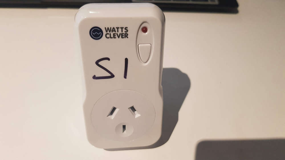
      The Switch
      0_1558261451143_switch.jpg

      The Hub
      0_1558261488775_node.jpg

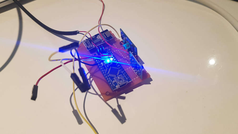
      Please excuse all the extra wires on the Nano; it stopped being recognised by all my computers so I had to program it using an FTDI adaptor.

      Here is the sketch. I am certain that it could be tidied up a lot.

      // Enable debug prints to serial monitor
      //#define MY_DEBUG
      
      // Enable and select radio type attached
      #define MY_RADIO_NRF24
      //#define MY_RADIO_RFM69
      
      // Enable repeater functionality for this node
      #define MY_REPEATER_FEATURE
      
      #include <SPI.h>
      #include <MySensors.h>
      #include <RCSwitch.h>
      
      #define MY_NODE_ID AUTO
      
      #define NUMBER_OF_PLUGS 6 // Total number of attached plugs
      
      #define SHORTPULSE 316
      #define LONGPULSE 818
      
      #define CODE_1On 4072574
      #define CODE_1Off 4072566
      #define CODE_2On 4072572
      #define CODE_2Off 4072564
      #define CODE_3On 4072570
      #define CODE_3Off 4072562
      #define CODE_4On 1386894
      #define CODE_4Off 1386886
      #define CODE_5On 1386892
      #define CODE_5Off 1386884
      #define CODE_6On 1386890
      #define CODE_6Off 1386882


      RCSwitch mySwitch = RCSwitch();
      
      void setup() {
        mySwitch.enableTransmit(4);
        mySwitch.setRepeatTransmit(15);
      }
      
      void presentation()
      {
        // Send the sketch version information to the gateway and Controller
        sendSketchInfo("433mhz HUB", "2.0");
      
        for (int sensor = 1 ; sensor <= NUMBER_OF_PLUGS; sensor++) {
          // Register all sensors to gw (they will be created as child devices)
          present(sensor, S_LIGHT);
        }
      }
      
      
      void loop()
      {
      
      }
      
      void receive(const MyMessage &message) {
        // We only expect one type of message from controller. But we better check anyway.
        if (message.type == V_LIGHT) {
          int incomingLightState =  message.getBool();
          int incomingOutlet = message.sensor;
      
          Serial.print("Outlet #: ");
          Serial.println(message.sensor);
          Serial.print("Command: ");
          Serial.println(message.getBool());
      
          if (incomingOutlet == 1) {
            if (incomingLightState == 1) {
              // Turn on  socket 1
              Serial.println("Turn on Socket 1");
              mySwitch.send(CODE_1On, 24); // These codes are unique to each outlet
              delay(50);
            }
            if (incomingLightState == 0)  {
              // Turn off socket 1
              Serial.println("Turn off Socket 1");
              mySwitch.send(CODE_1Off, 24);
              delay(50);
            }
          }
          if (incomingOutlet == 2) {
            if (incomingLightState == 1) {
              // Turn on  socket 2
              Serial.println("Turn on Socket 2");
              mySwitch.send(CODE_2On, 24);
              delay(50);
            }
            if (incomingLightState == 0)  {
              // Turn off socket 2
              Serial.println("Turn off Socket 2");
              mySwitch.send(CODE_2Off, 24);
              delay(50);
            }
          }
          if (incomingOutlet == 3) {
            if (incomingLightState == 1) {
              // Turn on  socket 3
              Serial.println("Turn on Socket 3");
              mySwitch.send(CODE_3On, 24);
              delay(50);
            }
            if (incomingLightState == 0)  {
              // Turn off socket 3
              Serial.println("Turn off Socket 3");
              mySwitch.send(CODE_3Off, 24);
              delay(50);
            }
          }
          if (incomingOutlet == 4) {
            if (incomingLightState == 1) {
              // Turn on  socket 4
              Serial.println("Turn on Socket 4");
              mySwitch.send(CODE_4On, 24);
              delay(50);
            }
            if (incomingLightState == 0)  {
              // Turn off socket 4
              Serial.println("Turn off Socket 4");
              mySwitch.send(CODE_4Off, 24);
              delay(50);
            }
          }
          if (incomingOutlet == 5) {
            if (incomingLightState == 1) {
              // Turn on  socket 5
              Serial.println("Turn on Socket 5");
              mySwitch.send(CODE_5On, 24);
              delay(50);
            }
            if (incomingLightState == 0)  {
              // Turn off socket 5
              Serial.println("Turn off Socket 5");
              mySwitch.send(CODE_5Off, 24);
              delay(50);
            }
          }
          if (incomingOutlet == 6) {
            if (incomingLightState == 1) {
              // Turn on  socket 6
              Serial.println("Turn on Socket 6");
              mySwitch.send(CODE_6On, 24);
              delay(50);
            }
            if (incomingLightState == 0)  {
              // Turn off socket 6
              Serial.println("Turn off Socket 6");
              mySwitch.send(CODE_6Off, 24);
              delay(50);
            }
          }
        }
        delay(50);
      }```
      
      I would like to give my sincere thanks to everyone here. I may not post all that much, but I enjoy reading what others are doing and trying to learn from it, although much of it is still way over my head! To @hek I still remember how excited I was when I found MySensors all those years ago, and I thank you and your crew for keeping this great community going!
      
      I am also certain that most of you won't get very much from this technical-wise; I just needed to share this for myself. Thank you all.
      posted in My Project
      Homer
      Homer
    • RE: rboard - Cheap relay/radio/arduino board ~$10

      Ok, looks like I am slowly getting there 🙂

      fyi I tried playing around with the above sketch, but it's a no go as Codebender tells me <Bounce2.h> is missing.

      posted in Hardware
      Homer
      Homer
    • RE: AI: What is the future of Wikis and Forums?

      I have just been using Chat GPT and it has been very careful. Just remember to be nice to it, so that when it takes over it will remember you as being nice and will hopefully give you an easier job when we all are enslaved by it hahaha

      posted in General Discussion
      Homer
      Homer
    • RE: DHT and DOOR sensor

      I can't believe I spotted am error in the code! I guess I'm starting to get a bit better at this! 😁😁

      posted in My Project
      Homer
      Homer
    • RE: rboard - Cheap relay/radio/arduino board ~$10

      @mfalkvidd said in rboard - Cheap relay/radio/arduino board ~$10:

      @homer that sketch was made for MySensors 1.x and needs to be converted to work for MySensors 2.x.
      Followthe guide at https://forum.mysensors.org/topic/4276/converting-a-sketch-from-1-5-x-to-2-0-x to convert it.

      Alternatively, remove MySensors 2 and install MySensors 1 instead.

      Thanks mate! I was thinking something like that might be the case, but I didn't know for sure.

      Thank you so much for pointing me in the right direction!!

      posted in Hardware
      Homer
      Homer
    • RE: Possible problem with sketch?

      Thank you for everyone's replies!

      posted in Troubleshooting
      Homer
      Homer
    • RE: Ethernet gateway

      @terence-faul I'm only new to this myself, so I can't help with anything specific, but I did a search and found another thread where someone was having issues with a similar setup to you. Maybe you might find some info there that helps you. The thread is here :
      https://forum.mysensors.org/topic/5059/ethernet-gateway-with-w5100

      posted in My Project
      Homer
      Homer
    • RE: rboard - Cheap relay/radio/arduino board ~$10

      I just wanted to say that I managed to upload a sketch and I have it working!

      I attempted to change the code so it was compatible but I gave that up and decided to merge two sketches. It was good fun, and I enjoyed learning!

      posted in Hardware
      Homer
      Homer
    • RE: Old user returning to Vera/MySensors

      Thank you for your responses! Exactly what I was after!

      posted in Vera
      Homer
      Homer
    • RE: Node not working

      I'm still keen to know if there is a way to call up any logs to check why things don't work, but at this stage I've been able to get the node to work again as it should. All I needed to do was give it more power.

      posted in Troubleshooting
      Homer
      Homer
    • RE: rboard - Cheap relay/radio/arduino board ~$10

      @alowhum said in rboard - Cheap relay/radio/arduino board ~$10:

      Could you share the sketch? Perhaps others will learn from it too?

      Great idea! ☺

      Here it is

      // Enable debug prints to serial monitor
      #define MY_DEBUG
      
      // Enable and select radio type attached
      #define MY_RADIO_NRF24
      //#define MY_RADIO_RFM69
      
      #include <SPI.h>
      #include <MySensors.h>
      #include <DallasTemperature.h>
      #include <OneWire.h>
      
      // Setup Relay bits
      #define RELAY_PIN 4  // Arduino Digital I/O pin number for first relay (second on pin+1 etc)
      #define NUMBER_OF_RELAYS 1 // Total number of attached relays
      #define RELAY_ON 1  // GPIO value to write to turn on attached relay
      #define RELAY_OFF 0 // GPIO value to write to turn off attached relay
      
      // Setup Temperature bits
      #define COMPARE_TEMP 1 // Send temperature only if changed? 1 = Yes 0 = No
      #define ONE_WIRE_BUS 14 // Pin where dallase sensor is connected 
      #define MAX_ATTACHED_DS18B20 16
      unsigned long SLEEP_TIME = 30000; // Sleep time between reads (in milliseconds)
      OneWire oneWire(ONE_WIRE_BUS); // Setup a oneWire instance to communicate with any OneWire devices (not just Maxim/Dallas temperature ICs)
      DallasTemperature sensors(&oneWire); // Pass the oneWire reference to Dallas Temperature.
      float lastTemperature[MAX_ATTACHED_DS18B20];
      int numSensors = 0;
      bool receivedConfig = false;
      bool metric = true;
      // Initialize temperature message
      MyMessage tempMsg(0, V_TEMP);
      
      void before()
      {
        for (int sensor = 1, pin = RELAY_PIN; sensor <= NUMBER_OF_RELAYS; sensor++, pin++) {
          // Then set relay pins in output mode
          pinMode(pin, OUTPUT);
          // Set relay to last known state (using eeprom storage)
          digitalWrite(pin, loadState(sensor) ? RELAY_ON : RELAY_OFF);
        }
      
        // Startup up the OneWire library
        sensors.begin();
      }
      
      void setup()
      {
        // requestTemperatures() will not block current thread
        sensors.setWaitForConversion(false);
      }
      
      void presentation()
      {
        // Send the sketch version information to the gateway and Controller
        sendSketchInfo("Temp and Relay", "1.0");
      
        // Fetch the number of attached temperature sensors
        numSensors = sensors.getDeviceCount();
      
        // Present all sensors to controller
        for (int i = 0; i < numSensors && i < MAX_ATTACHED_DS18B20; i++) {
          present(i, S_TEMP);
      
          for (int sensor = 1, pin = RELAY_PIN; sensor <= NUMBER_OF_RELAYS; sensor++, pin++) {
            // Register all sensors to gw (they will be created as child devices)
            present(sensor, S_BINARY);
      
          }
        }
      }
      
      void loop()
      {
        // Fetch temperatures from Dallas sensors
        sensors.requestTemperatures();
      
        // query conversion time and sleep until conversion completed
        int16_t conversionTime = sensors.millisToWaitForConversion(sensors.getResolution());
        // sleep() call can be replaced by wait() call if node need to process incoming messages (or if node is repeater)
        wait(conversionTime);
      
        // Read temperatures and send them to controller
        for (int i = 0; i < numSensors && i < MAX_ATTACHED_DS18B20; i++) {
      
          // Fetch and round temperature to one decimal
          float temperature = static_cast<float>(static_cast<int>((getControllerConfig().isMetric ? sensors.getTempCByIndex(i) : sensors.getTempFByIndex(i)) * 10.)) / 10.;
      
          // Only send data if temperature has changed and no error
      #if COMPARE_TEMP == 1
          if (lastTemperature[i] != temperature && temperature != -127.00 && temperature != 85.00) {
      #else
          if (temperature != -127.00 && temperature != 85.00) {
      #endif
      
            // Send in the new temperature
            send(tempMsg.setSensor(i).set(temperature, 1));
            // Save new temperatures for next compare
            lastTemperature[i] = temperature;
          }
        }
        wait(SLEEP_TIME);
      }
      
      void receive(const MyMessage &message)
      {
        // We only expect one type of message from controller. But we better check anyway.
        if (message.type == V_STATUS) {
          // Change relay state
          digitalWrite(message.sensor - 1 + RELAY_PIN, message.getBool() ? RELAY_ON : RELAY_OFF);
          // Store state in eeprom
          saveState(message.sensor, message.getBool());
          // Write some debug info
          Serial.print("Incoming change for sensor:");
          Serial.print(message.sensor);
          Serial.print(", New status: ");
          Serial.println(message.getBool());
        }
      }
      
      posted in Hardware
      Homer
      Homer
    • RE: Example sketch not updated to new Mysensors version

      UPDATE

      Once I added the suggested modified libraries, it compiles.

      I did find a spelling mistake that @hek might be interested in: In the EXAMPLE section it states "DTH" when it should be "DHT".

      posted in Troubleshooting
      Homer
      Homer
    • RE: LED Dimmer not working as it should

      0_1557905956962_20190515_171044.jpg

      0_1557905980738_20190515_171052.jpg

      posted in Troubleshooting
      Homer
      Homer
    • RE: Recommendations for soldering temperature

      Thanks!

      I went and bought a new tip today. The one I had was pointy and I was struggling to heat the circuit board while heating the leg of the Arduino. So I went and bought one that has a flat spot which I saw on a YouTube video. Now I can heat both the board and the leg at the same time and do it properly so the solder flows into the hole. My soldering looks better already, and I'm soldering at a little over 350 degrees C now.

      posted in Troubleshooting
      Homer
      Homer
    • RE: Adding sensor to controller when it's part of gateway

      @skywatch said in Adding sensor to controller when it's part of gateway:

      @Homer I am no expert in this but I have thought of something that you could try.

      If I understand correctly you have added one RF433 transmitter to the GW node? This then sends data (On/Off) to the 6 RF433 sockets.

      If so then the gateway only has one child, the RF433 transmitter, the sockets are not 'attached' to the GW.

      So instead of presenting all 6 sockets, just present the one RF433 transmitter and see if that helps? All the code for the actions is in the receive section anyway.

      This is how I did it with IR blaster and it works fine, changing IR for RF should not make a difference in the structure.

      Hold on - I think I got it.....!!!!

      You are using S_LIGHT in presentation - that is no longer supported.

      Change S_LIGHT to S_BINARY.

      Another thing is that although you are presenting your child(s), you do not define the type. I would expect a MyMessage in there somewhere at the start.

      So add MyMessage msgyourmessage (child_id, V_STATUS);

      And finally change V_LIGHT to V_STATUS in the receive function.

      Thanks! Yes, you got it lol!!

      The thing that is weird is that all I did was add the rf433 controlled devices from a working sketch to the gateway sketch, so why does it work when it's separate but not when it's part of the gateway sketch? If S_LIGHT is no longer supported, why does it work on a standalone sensor?

      posted in Troubleshooting
      Homer
      Homer
    • Sensors are sporadically showing up

      Unfortunately when I started playing around with Mysensors a week or so ago, life was a little quieter than what it is right now. After playing around with my Gateway I have to readd all my sensors to it, and I was silly today and have tried to combine two sensors that I have had running flawlessly, into one sensor. Big mistake.... I've had a couple issues happen in my family and now I've stuffed up my garage door operation... I have been working on the sketch now for a couple hours and I just can't seem to work out the problem.

      I have built a sensor which will operate 2 relays, and will also report the state of my two garage doors. My controller is Vera 3. What is happening is something weird; the repeater part always shows up after inclusion, but sometimes it shows the 2 door sensors, then other times it shows the 2 relays. So my guess is that the issue is around Presentation, but it all looks fine to me, and when the relay and the door sensor sketches are uploaded individually, each sensor shows up as they should. I have even tried different power supplies in case it was a power issue, but the issue is still there.

      Here is my sketch:

      // Enable debug prints to serial monitor
      #define MY_DEBUG
      
      // Enable repeater functionality for this node
      #define MY_REPEATER_FEATURE
      
      // Enable and select radio type attached
      #define MY_RADIO_NRF24
      //#define MY_RADIO_RFM69
      #define MY_RF24_PA_LEVEL RF24_PA_HIGH
      
      
      #include <SPI.h>
      #include <MySensors.h>
      #include <Bounce2.h>
      
      #define RELAY_PIN 4  // Arduino Digital I/O pin number for first relay (second on pin+1 etc)
      #define NUMBER_OF_RELAYS 2 // Total number of attached relays
      #define RELAY_ON 1  // GPIO value to write to turn on attached relay
      #define RELAY_OFF 0 // GPIO value to write to turn off attached relay
      
      #define SSR_A_ID 1   // Id of the sensor child
      #define SSR_B_ID 2   // Id of the sensor child
      
      const int buttonPinA = 6;
      const int buttonPinB = 7;
      
      int oldValueA = 0;
      int oldValueB = 0;
      
      bool stateA = false;
      bool stateB = false;
      
      Bounce debouncerA = Bounce();
      Bounce debouncerB = Bounce();
      
      // Change to V_LIGHT if you use S_LIGHT in presentation below
      MyMessage msgA(SSR_A_ID, V_TRIPPED);
      MyMessage msgB(SSR_B_ID, V_TRIPPED);
      
      void before()
      {
        for (int sensor = 1, pin = RELAY_PIN; sensor <= NUMBER_OF_RELAYS; sensor++, pin++) {
          // Then set relay pins in output mode
          pinMode(pin, OUTPUT);
          // Set relay to last known state (using eeprom storage)
          digitalWrite(pin, loadState(sensor) ? RELAY_ON : RELAY_OFF);
        }
      }
      
      void setup()
      {
        // Setup the button
        pinMode(buttonPinA, INPUT_PULLUP); // Setup the button Activate internal pull-up
        pinMode(buttonPinB, INPUT_PULLUP); // Setup the button Activate internal pull-up
      
      
        // After setting up the buttons, setup debouncer
        debouncerA.attach(buttonPinA);
        debouncerA.interval(5);
        debouncerB.attach(buttonPinB);
        debouncerB.interval(5);
      
      }
      
      void presentation()
      {
        // Send the sketch version information to the gateway and Controller
        sendSketchInfo("Garage door Operate/State", "1.0");
      
        // Register binary input sensor to gw (they will be created as child devices)
        // You can use S_DOOR, S_MOTION or S_LIGHT here depending on your usage.
        // If S_LIGHT is used, remember to update variable type you send in. See "msg" above.
        present(SSR_A_ID, S_DOOR);
        present(SSR_B_ID, S_DOOR);
      
        for (int sensor = 1, pin = RELAY_PIN; sensor <= NUMBER_OF_RELAYS; sensor++, pin++) {
          // Register all sensors to gw (they will be created as child devices)
          present(sensor, S_BINARY);
        }
      }


      //  Check if digital input has changed and send in new value
      void loop()
      {
        debouncerA.update();
        // Get the update value
        int valueA = debouncerA.read();
      
        if (valueA != oldValueA) {
          // Send in the new value
          send(msgA.set(valueA == HIGH ? 0 : 1));
          oldValueA = valueA;
      
        }
      
        debouncerB.update();
        // Get the update value
        int valueB = debouncerB.read();
      
        if (valueB != oldValueB) {
          // Send in the new value
          send(msgB.set(valueB == HIGH ? 0 : 1));
          oldValueB = valueB;
        }
      }
      
      void receive(const MyMessage &message)
      {
        // We only expect one type of message from controller. But we better check anyway.
        if (message.type == V_STATUS) {
          // Change relay state
          digitalWrite(message.sensor - 1 + RELAY_PIN, message.getBool() ? RELAY_ON : RELAY_OFF);
          // Store state in eeprom
          saveState(message.sensor, message.getBool());
          // Write some debug info
          Serial.print("Incoming change for sensor:");
          Serial.print(message.sensor);
          Serial.print(", New status: ");
          Serial.println(message.getBool());
        }
      }
      

      I am sorry to be asking yet again for help. I really have tried for so long today to get this to work on my own, but I can't see the issue. I do have the flu, so maybe that isn't helping!

      posted in Troubleshooting
      Homer
      Homer
    • RE: Have I blown the MOSFETS?

      I found a YouTube video that explained how to test them, but my multimeter must not be up to the job. So I created a single led dimmer sensor and hooked it up to the three MOSFETS one at a time to test, and they seem to work as they should. So my issue must be with the sketch.

      Mods, you can delete this thread if you like.

      posted in Troubleshooting
      Homer
      Homer