Why are you using a usb to serial adapter to connect the arduino to the raspberry? The raspberry has an onboard uart at /dev/ttyAMA0. I am using the internal uart and cannot reproduce this kind of error.
Best posts made by Jan Gatzke
-
RE: Serial Gateway connection to Openhab
-
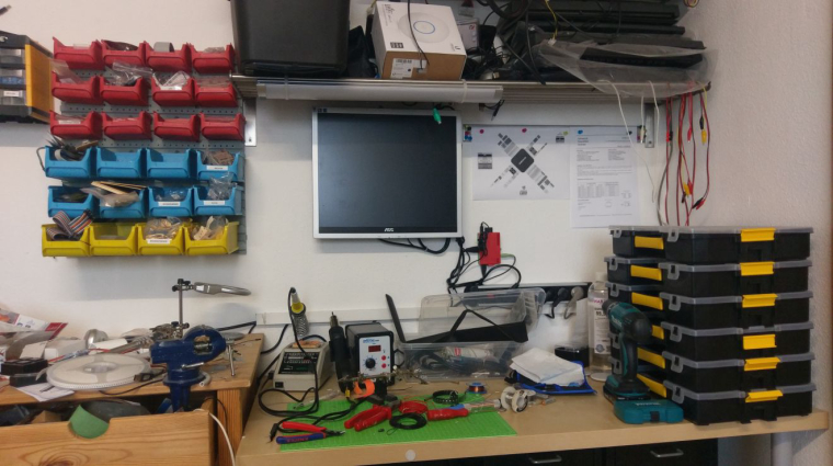
RE: Your workshop :)
I am especially proud of my 20 years old analog soldering station.
-
MySensors controlled heating
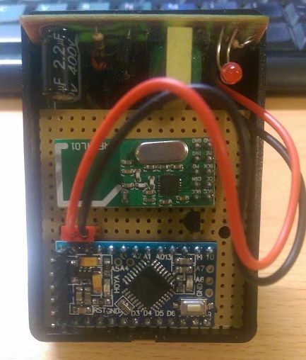
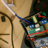
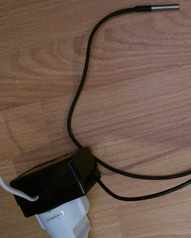
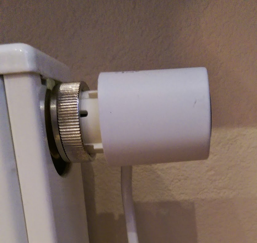
I have made a node which measures the temperature using a DS18b20 and controls an electric heating valve (http://www.ebay.de/itm/350991304709?_trksid=p2057872.m2749.l2649&ssPageName=STRK%3AMEBIDX%3AIT) using a MOC3023 optocoupler with triac output (little white chip, works like a solid state relay. Only for small currents, but very cheap). The power supply is the pcb of a usb power supply.
Pictures:
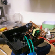
The code is a simple combination of the ds18b20 and the relay actuator examples.
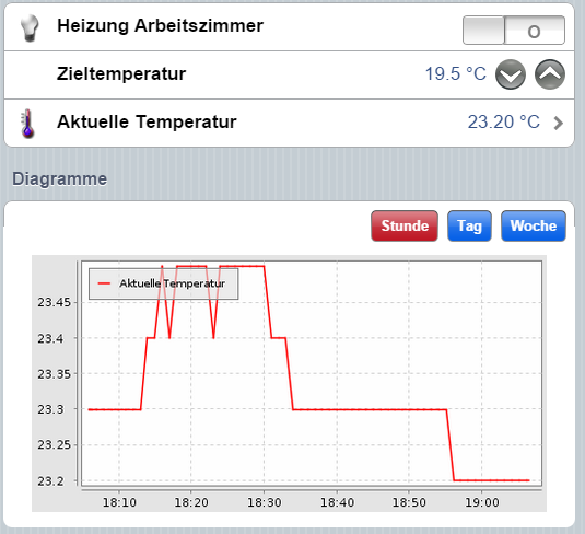
Using openHAB I can set a target temperature. When the temperature is below the target temperature the valve is opened. Else the valve is closed. Since I am using a NC (normally closed) valve, the valve opens when connected to power.
-
RE: [Tutorial] openHAB with serial gateway
Nice tutorial. I discarded my own incoming rules and am now using this solution. I have extended the rule by a few additional sub types:
if (subType == V_LIGHT_LEVEL){ postUpdate(sensorToItemsMap.get( nodeId + ";" + childId + ";"), msg) println ("Light item: " + sensorToItemsMap.get( nodeId + ";" + childId + ";") + " light: " + msg ) } if (subType == V_VOLTAGE){ postUpdate(sensorToItemsMap.get( nodeId + ";" + childId + ";"), msg) println ("Voltage item: " + sensorToItemsMap.get( nodeId + ";" + childId + ";") + " voltage: " + msg ) } if (subType == V_LOCK_STATUS){ var String lockstatus="OPEN" if (msg=="1"){ lockstatus="CLOSED" } postUpdate(sensorToItemsMap.get( nodeId + ";" + childId + ";"), lockstatus) println ("Door/Window item: " + sensorToItemsMap.get( nodeId + ";" + childId + ";") + " Status: " + lockstatus ) } if (subType == V_TRIPPED){ var String tripped="OFF" if (msg=="1"){ tripped="ON" } postUpdate(sensorToItemsMap.get( nodeId + ";" + childId + ";"), tripped) println ("Button/Contact item: " + sensorToItemsMap.get( nodeId + ";" + childId + ";") + " Status: " + tripped ) } if (subType == V_LIGHT){ var String light="OFF" if (msg=="1"){ light="ON" } postUpdat(sensorToItemsMap.get( nodeId + ";" + childId + ";"), light) println ("Light item: " + sensorToItemsMap.get( nodeId + ";" + childId + ";") + " Light: " + light ) }
-
RE: Newbie - Do not succeed to start
I think the generic board does not work because the default settings are not sufficient for ms. Be sure the settings match your actual esp8266 module.
Did you pull down gpio0 when you powered on the module? This activates the programming mode.
If you want to go the easy way just get a node mcu compatible board like wemos d1 mini. It has an onboard USB port and you don't have to manually put it in programming mode.
Mqtt adds complexity. If you don't need it you should choose plain ms. -
RE: Sketch works on Uno, but not pro mini
This could be a power problem. The UNO has a much better voltage regulator circuit. Did you connect a capacitor to the nrf24?
-
RE: Minding the robot
And how do you know where your wife is and whether she got stuck?
-
RE: Serial Gateway connection to Openhab
@jemish This is to basic to earn an answer. I suggest you start reading at http://www.mysensors.org .
-
RE: Radio FAIL after ~3 weeks [SOLVED]
@Reza
Which NRF Modules do you use? 50 meter with a wall in between wont function properly with the cheap ones. You need something like this for the Job: -
RE: Connect raspberry and arduino nano with USB
The USB connection between the RPi and the Nano is known to make problems. Just use the Pi's UART. Connect RX of the Pi with TX of the Arduino and vice versa. See https://github.com/openhab/openhab/wiki/Serial-Binding for using the Pi's UART with openHAB. Rock stable and easy.
-
RE: [Tutorial] openHAB with serial gateway
I don't understand why everybody is using an USB connection for the serial gateway when openHAB is running on a raspberry pi. The pi has a rock stable uart with 3.3V logic. There is no need to convert the arduinos uart to USB. Just connect RX to TX and TX to RX. Connect ground to ground and VCC of the arduino to the 3.3V pin of the pi and you are done. The official openHAB wiki contains instructions on how to use the onboard uart of the pi: https://github.com/openhab/openhab/wiki/Serial-Binding
-
RE: Radio FAIL after ~3 weeks [SOLVED]
Great analysis. I will surely send you my code for review next time.
-
RE: Need working example battery powered sensor
@Jan-Gatzke said:
I have never done this before. But basically you need the c code of the bootloader for your Arduino. Then open it with a text editor and change the f_cpu value. Then compile and flash it using avrdude.
I googled and found this:
http://angryelectron.com/how-to-update-the-bootloader-on-arduino-pro-mini-328/I would use Atmel studio for these low level tasks if you are running in Windows.
Edit: Found already compiled bootloaders here: http://forum.arduino.cc/index.php?topic=160647.15
-
RE: Radio FAIL after ~3 weeks [SOLVED]
The Problem is most likely a problem with your hardware. Try to lower the distance and see if the problem still exists. If not you should replace your radios. Look for radios with pa / lna.
-
RE: How to best set up a bigger mysensors installation
There can be only one gateway in one network. Auto fallback does not exist afaik. You can have one network per floor. This means you have to choose another channel/frequency.
I have used one repeater in a similar scenario. Problems occur when the node occasionally can reach the gateway directly. I had to specify the parent node/repeater. Now it works well. -
New version of the MySensors adapter
I have just commited some changes to the iobroker MySensors Adapter on github. All set command are send with ack flag now and the states in iobroker get an ack on successful transmission, too. The new version is not being published via the iobroker admin, yet. You have to download it from github and copy it to your iobroker directory. Please test and report any problems you are facing.
-
RE: π¬ OH MySensors RGBW Controller
I got my v1.3 pcbs from Smart Prototyping. Quality is good. The controller works fine BUT the sketch version in your github repo is broken. Seems like the non linear fading part never got finished. I am now using linear fading and the sketch is working.
-
RE: light and relay turn on automatically !
He only wrote about a blinking led not about the whole node failing.
-
RE: π¬ OH MySensors RGBW Controller
As promised I had a look at the sketch. The node can now save and restore values for rgbw, dimming and status to/from the controller. I had a look at the non linear fading, too. I got it partially working and refreshed my math knowledge a lot.
In the end I removed the code for it because it made the sketch much more complicated and I didn't like the results. The formula from the original sketch was ok for fading a single LED from 0% to 100%. It didn't cover other starting values and the combination of the colors. IMHO only the dimming can be done non linear without problems. For this I would use a static table of PWM values and percent values. Doing the log calculations on the pro mini seems to be too slow for a smooth fading. I saw massive flickering.Here is the sketch:
/** Based on the MySensors Project: http://www.mysensors.org This sketch controls a (analog)RGBW strip by listening to new color values from a (domoticz) controller and then fading to the new color. Version 1.1 - Added save/restore of values to/from controller, removed non linear fading code Version 1.0 - Changed pins and gw definition Version 0.9 - Oliver Hilsky **/ #define MY_DEBUG #define SN "RGBW 01" #define SV "1.1" #define MY_RADIO_NRF24 // change the pins to free up the pwm pin for led control #define MY_RF24_CE_PIN 4 //<-- NOTE!!! changed, the default is 9 #define MY_RF24_CS_PIN 10 // default is 10 // Set LOW transmit power level as default, if you have an amplified NRF-module and // power your radio separately with a good regulator you can turn up PA level. #define MY_RF24_PA_LEVEL RF24_PA_LOW //Uncomment to enable repeater mode //#define MY_REPEATER_FEATURE //Uncomment to assign static node ID //#define MY_NODE_ID 9 // Load mysensors library #include <MySensors.h> // Load Serial Peripheral Interface library #include <SPI.h> // Arduino pin attached to driver pins #define RED_PIN 3 #define WHITE_PIN 9 #define GREEN_PIN 5 #define BLUE_PIN 6 #define NUM_CHANNELS 4 // how many channels, RGBW=4 RGB=3... #define CHILD_ID 1 // Smooth stepping between the values #define STEP 1 #define INTERVAL 10 MyMessage lastvalueMsg(CHILD_ID, V_VAR1); MyMessage lastisonMsg(CHILD_ID, V_VAR2); MyMessage lastdimmMsg(CHILD_ID, V_VAR3); // Stores the current color settings byte channels[4] = {RED_PIN, GREEN_PIN, BLUE_PIN, WHITE_PIN}; byte values[4] = {0, 0, 0, 0}; byte target_values[4] = {0, 0, 0, 0}; // stores dimming level byte dimming = 100; byte target_dimming = 100; // tracks if the strip should be on of off boolean isOn = false; // tracks if the strip's last status was off. This overrides isOn at startup boolean wasOff = true; //tracks if the old values have bben requested from the controller. This prevents the request from being send multipΓle times in the main loop. boolean valuesrequested = false; // time tracking for updates unsigned long lastupdate = millis(); void setup() { // Set all channels to output (pin number, type) for (int i = 0; i < NUM_CHANNELS; i++) { pinMode(channels[i], OUTPUT); } // debug if (isOn) { Serial.println("RGBW is running..."); } } void presentation() { // Send the sketch version information to the gateway and Controller sendSketchInfo(SN, SV); // Register this device as Waterflow sensor present(CHILD_ID, S_RGBW_LIGHT, SN, true); } void loop() { if (!valuesrequested) { // get old values if this is just a restart Serial.println("Requesting old values..."); //Request RGBW values request( CHILD_ID, V_VAR1 ); wait(200); //Request Status request( CHILD_ID, V_VAR2 ); wait(200); //Request dimm level request( CHILD_ID, V_VAR3 ); valuesrequested = true; } // set the new light colors if (millis() > lastupdate + INTERVAL) { updateLights(); lastupdate = millis(); } } // callback function for incoming messages void receive(const MyMessage &message) { Serial.print("Got a message - "); Serial.print("Messagetype is: "); Serial.println(message.type); // acknoledgment if (message.isAck()) { Serial.println("Got ack from gateway"); } // new dim level else if (message.type == V_DIMMER or message.type == V_VAR3) { Serial.println("Dimming to "); Serial.println(message.getString()); target_dimming = message.getByte(); send(lastdimmMsg.set(target_dimming)); if (!wasOff) { // a new dimmer value also means on, no seperate signal gets send (by domoticz) isOn = true; send(lastisonMsg.set(isOn)); } } // on / off message else if (message.type == V_STATUS or message.type == V_VAR2) { Serial.print("Turning light "); isOn = message.getInt(); if (isOn) { Serial.println("on"); wasOff = false; } else { Serial.println("off"); } send(lastisonMsg.set(isOn)); } // new color value else if (message.type == V_RGBW or message.type == V_VAR1) { const char * rgbvalues = message.getString(); send(lastvalueMsg.set(rgbvalues)); inputToRGBW(rgbvalues); if (!wasOff) { // a new color also means on, no seperate signal gets send (by domoticz); needed e.g. for groups isOn = true; send(lastisonMsg.set(isOn)); } } } // this gets called every INTERVAL milliseconds and updates the current pwm levels for all colors void updateLights() { // update pin values -debug //Serial.println(greenval); //Serial.println(redval); //Serial.println(blueval); //Serial.println(whiteval); //Serial.println(target_greenval); //Serial.println(target_redval); //Serial.println(target_blueval); //Serial.println(target_whiteval); //Serial.println("+++++++++++++++"); // for each color for (int v = 0; v < NUM_CHANNELS; v++) { if (values[v] < target_values[v]) { values[v] += STEP; if (values[v] > target_values[v]) { values[v] = target_values[v]; } } if (values[v] > target_values[v]) { values[v] -= STEP; if (values[v] < target_values[v]) { values[v] = target_values[v]; } } } // dimming if (dimming < target_dimming) { dimming += STEP; if (dimming > target_dimming) { dimming = target_dimming; } } if (dimming > target_dimming) { dimming -= STEP; if (dimming < target_dimming) { dimming = target_dimming; } } /* // debug - new values Serial.println(greenval); Serial.println(redval); Serial.println(blueval); Serial.println(whiteval); Serial.println(target_greenval); Serial.println(target_redval); Serial.println(target_blueval); Serial.println(target_whiteval); Serial.println("+++++++++++++++"); */ // set actual pin values for (int i = 0; i < NUM_CHANNELS; i++) { if (isOn) { // normal fading analogWrite(channels[i], dimming / 100.0 * values[i]); } else { analogWrite(channels[i], 0); } } } // converts incoming color string to actual (int) values // ATTENTION this currently does nearly no checks, so the format needs to be exactly like domoticz sends the strings void inputToRGBW(const char * input) { Serial.print("Got color value of length: "); Serial.println(strlen(input)); if (strlen(input) == 6) { Serial.println("new rgb value"); target_values[0] = fromhex (& input [0]); target_values[1] = fromhex (& input [2]); target_values[2] = fromhex (& input [4]); target_values[3] = 0; } else if (strlen(input) == 9) { Serial.println("new rgbw value"); target_values[0] = fromhex (& input [1]); // ignore # as first sign target_values[1] = fromhex (& input [3]); target_values[2] = fromhex (& input [5]); target_values[3] = fromhex (& input [7]); } else { Serial.println("Wrong length of input"); } Serial.print("New color values: "); Serial.println(input); for (int i = 0; i < NUM_CHANNELS; i++) { Serial.print(target_values[i]); Serial.print(", "); } Serial.println(""); Serial.print("Dimming: "); Serial.println(dimming); } // converts hex char to byte byte fromhex (const char * str) { char c = str [0] - '0'; if (c > 9) c -= 7; int result = c; c = str [1] - '0'; if (c > 9) c -= 7; return (result << 4) | c; }
-
Serial Gateway restarting
My serial Gateway (2.1.1) is restarting in some situations. I have already replaced the hardware. It is running on an 3.3V Arduino. I am using an uncostomized version of the serial gateway sketch. Only the baud rate is reduced because of the 8 Mhz Arduino. The recommended capacitor is in place. I am using the "Newbie PCB" with an dedicated voltage regulator.
After some testing it seems that the restarts always occur when the gateway fails to transmit a message to a node. I had one node that was temporary offline. This node is normaly activated via some lua scripts in domotics. While it was offline this always caused a gateway restart.2017-04-19 23:27:00.450 EventSystem: Event triggered: Heizung Arbeitszimmer_2 2017-04-19 23:27:00.600 MySensors: Gateway Ready... 2017-04-19 23:27:00.676 MySensors: Gateway Version: 2.1.1 2017-04-19 23:27:01.801 MySensors: Gateway Ready... 2017-04-19 23:27:01.877 MySensors: Gateway Version: 2.1.1
I have an LED actuator node which is only reliably reachable via a repeater. It seems like the gateway tries to reach it directly which sometimes fails. In these situations the switching is delayed by about 2 seconds and according to the logs the gateway restarts.
This does not occur with nodes near the gateway.
Is this a bug or expected behaviour? Or am I doing something completely wrong?
-
RE: π¬ Sonoff relay using MySensors ESP8266 wifi or mqtt gateway
This is not really a gateway. You can use the esp8266 gateway sketch, disable the nrf24 / rfm69 and directly attach sensors. So basically it's an relay actuator which is configured as a mysensors gateway.
-
RE: When powered from usb, nrf24I01 is ok, from external Power not
@mfalkvidd I bet the serial gateway. 2.1.1 is bugy. I solved this problem by upgrading to the 2.2 beta from github.
-
RE: π¬ Sonoff relay using MySensors ESP8266 wifi or mqtt gateway
Ok, I just wiped out (hopefully) all my passwords and IP information.
/** The MySensors Arduino library handles the wireless radio link and protocol between your home built sensors/actuators and HA controller of choice. The sensors forms a self healing radio network with optional repeaters. Each repeater and gateway builds a routing tables in EEPROM which keeps track of the network topology allowing messages to be routed to nodes. Created by Henrik Ekblad <henrik.ekblad@mysensors.org> Copyright (C) 2013-2015 Sensnology AB Full contributor list: https://github.com/mysensors/Arduino/graphs/contributors Documentation: http://www.mysensors.org Support Forum: http://forum.mysensors.org This program is free software; you can redistribute it and/or modify it under the terms of the GNU General Public License version 2 as published by the Free Software Foundation. ******************************* REVISION HISTORY Version 1.0 - Henrik EKblad Contribution by a-lurker and Anticimex, Contribution by Norbert Truchsess <norbert.truchsess@t-online.de> Contribution by Ivo Pullens (ESP8266 support) DESCRIPTION The EthernetGateway sends data received from sensors to the WiFi link. The gateway also accepts input on ethernet interface, which is then sent out to the radio network. VERA CONFIGURATION: Enter "ip-number:port" in the ip-field of the Arduino GW device. This will temporarily override any serial configuration for the Vera plugin. E.g. If you want to use the defualt values in this sketch enter: 192.168.178.66:5003 LED purposes: - To use the feature, uncomment WITH_LEDS_BLINKING in MyConfig.h - RX (green) - blink fast on radio message recieved. In inclusion mode will blink fast only on presentation recieved - TX (yellow) - blink fast on radio message transmitted. In inclusion mode will blink slowly - ERR (red) - fast blink on error during transmission error or recieve crc error See http://www.mysensors.org/build/esp8266_gateway for wiring instructions. nRF24L01+ ESP8266 VCC VCC CE GPIO4 CSN/CS GPIO15 SCK GPIO14 MISO GPIO12 MOSI GPIO13 GND GND Not all ESP8266 modules have all pins available on their external interface. This code has been tested on an ESP-12 module. The ESP8266 requires a certain pin configuration to download code, and another one to run code: - Connect REST (reset) via 10K pullup resistor to VCC, and via switch to GND ('reset switch') - Connect GPIO15 via 10K pulldown resistor to GND - Connect CH_PD via 10K resistor to VCC - Connect GPIO2 via 10K resistor to VCC - Connect GPIO0 via 10K resistor to VCC, and via switch to GND ('bootload switch') Inclusion mode button: - Connect GPIO5 via switch to GND ('inclusion switch') Hardware SHA204 signing is currently not supported! Make sure to fill in your ssid and WiFi password below for ssid & pass. */ #include <SPI.h> // Enable debug prints to serial monitor #define MY_DEBUG // Use a bit lower baudrate for serial prints on ESP8266 than default in MyConfig.h #define MY_BAUD_RATE 9600 // Enables and select radio type (if attached) //#define MY_RADIO_NRF24 //#define MY_RADIO_RFM69 #define MY_GATEWAY_ESP8266 #define MY_ESP8266_SSID "MySSID" #define MY_ESP8266_PASSWORD "MyPSK" // Enable UDP communication //#define MY_USE_UDP // Set the hostname for the WiFi Client. This is the hostname // it will pass to the DHCP server if not static. // #define MY_ESP8266_HOSTNAME "sensor-gateway" // Enable MY_IP_ADDRESS here if you want a static ip address (no DHCP) #define MY_IP_ADDRESS 192,168,1,200 // If using static ip you need to define Gateway and Subnet address as well #define MY_IP_GATEWAY_ADDRESS 192,168,1,254 #define MY_IP_SUBNET_ADDRESS 255,255,255,0 // The port to keep open on node server mode #define MY_PORT 5003 // How many clients should be able to connect to this gateway (default 1) #define MY_GATEWAY_MAX_CLIENTS 2 // Controller ip address. Enables client mode (default is "server" mode). // Also enable this if MY_USE_UDP is used and you want sensor data sent somewhere. //#define MY_CONTROLLER_IP_ADDRESS 192, 168, 178, 68 // Enable inclusion mode //#define MY_INCLUSION_MODE_FEATURE // Enable Inclusion mode button on gateway // #define MY_INCLUSION_BUTTON_FEATURE // Set inclusion mode duration (in seconds) //#define MY_INCLUSION_MODE_DURATION 60 // Digital pin used for inclusion mode button //#define MY_INCLUSION_MODE_BUTTON_PIN 3 // Flash leds on rx/tx/err // #define MY_LEDS_BLINKING_FEATURE // Set blinking period // #define MY_DEFAULT_LED_BLINK_PERIOD 300 // Led pins used if blinking feature is enabled above //#define MY_DEFAULT_ERR_LED_PIN 16 // Error led pin //#define MY_DEFAULT_RX_LED_PIN 16 // Receive led pin //#define MY_DEFAULT_TX_LED_PIN 16 // the PCB, on board LED #if defined(MY_USE_UDP) #include <WiFiUDP.h> #else #include <ESP8266WiFi.h> #endif #include <WiFiClient.h> #include <ESP8266WebServer.h> #include <ESP8266mDNS.h> #include <ESP8266HTTPUpdateServer.h> #include <MySensors.h> #define RELAY_1_Pin 12 #define LED_1_Pin 13 #define TOUCH_1_Pin 0 #define RELAY_1 1 #define TOUCH_1 3 #define TOUCH_2 4 boolean relayon = false; int activescene = 1; volatile unsigned long LastChange = 0; volatile boolean RelayToggleRequired = false; volatile boolean SceneSwitchRequired = false; volatile boolean SceneSwitchTriggeredByTimeout = false; volatile boolean SceneSwitchTriggeredByTimeout2 = false; MyMessage msg(RELAY_1, V_LIGHT); MyMessage msg1(TOUCH_1, V_SCENE_ON); MyMessage msg2(TOUCH_2, V_LIGHT); ESP8266WebServer httpServer(80); ESP8266HTTPUpdateServer httpUpdater; const char* host = "sonofftouch1"; const char* location = "Couch"; char* update_username = "admin"; //Benutzername zum login fΓΌr die OTA-Programmierung char* update_password = "MyPassword"; //Passwort String webPage = ""; unsigned long lastheartbeat = 0; void buttonChangeCallback() { if (digitalRead(TOUCH_1_Pin) == 1) { //LED off for feedback digitalWrite(LED_1_Pin, 1); //Button has been released, trigger one of the two possible options. if (millis() - LastChange > 500) { //Long Press if (!SceneSwitchTriggeredByTimeout) { SceneSwitchRequired = true; } } else if (millis() - LastChange > 50) { //Short press at least 50 ms for debounce RelayToggleRequired = true; } else { //Too short to register as a press } } else { //LED on for feedback digitalWrite(LED_1_Pin, 0); //Just been pressed - do nothing until released. } LastChange = millis(); SceneSwitchTriggeredByTimeout = false; SceneSwitchTriggeredByTimeout2 = false; } void setup() { webPage += "<h1>ESP8266 Web Server</h1>"; webPage += "<br><h1>"; webPage += host; webPage += "</h1>"; webPage += "<br><h1>"; webPage += location; webPage += "</h1>"; webPage += "<br><a href=/update>Click here to update</a>"; pinMode(TOUCH_1_Pin, INPUT_PULLUP); // sets the digital pin as output pinMode(RELAY_1_Pin, OUTPUT); pinMode(LED_1_Pin, OUTPUT); //LED off digitalWrite(LED_1_Pin, 1); MDNS.begin(host); httpUpdater.setup(&httpServer, "/update", update_username, update_password); httpServer.begin(); MDNS.addService("http", "tcp", 80); httpServer.on("/", []() { httpServer.send(200, "text/html", webPage); }); Serial.println("Enabling touch switch interrupt"); attachInterrupt(digitalPinToInterrupt(TOUCH_1_Pin), buttonChangeCallback, CHANGE); } void presentation() { // Send the sketch version information to the gateway and Controller sendSketchInfo("Sonoff Touch Mysensors", "1.0"); present(RELAY_1, S_LIGHT, "single click/onboard relay"); present(TOUCH_1, S_SCENE_CONTROLLER, "double click/scene controller"); present(TOUCH_2, S_LIGHT, "long press virtuel switch"); } void loop() { httpServer.handleClient(); if (millis() - lastheartbeat > 30000) { //sendHeartbeat(); sendBatteryLevel(90); lastheartbeat = millis(); } if (RelayToggleRequired) { ToggleRelay(); RelayToggleRequired = false; } if (SceneSwitchRequired) { SwitchScene(); SceneSwitchRequired = false; } if (millis() - LastChange > 600) { if (digitalRead(TOUCH_1_Pin) == 0) { if (SceneSwitchTriggeredByTimeout == false) { SceneSwitchTriggeredByTimeout = true; SwitchScene(); } } } if (millis() - LastChange > 3000) { if (digitalRead(TOUCH_1_Pin) == 0) { if (SceneSwitchTriggeredByTimeout2 == false) { SceneSwitchTriggeredByTimeout2 = true; SwitchSceneOff(); } } } } void receive(const MyMessage &message) { // We only expect one type of message from controller. But we better check anyway. if (message.type == V_LIGHT) { // Change relay state if (message.sensor == RELAY_1) { digitalWrite(RELAY_1_Pin, message.getBool() ? 1 : 0); relayon = message.getBool() ? 1 : 0; } // Write some debug info Serial.print("Incoming change for sensor:"); Serial.print(message.sensor); Serial.print(", New status: "); Serial.println(message.getBool()); } } void ToggleRelay() { Serial.println("Single Click"); if (relayon) { digitalWrite(RELAY_1_Pin, 0); relayon = false; } else { digitalWrite(RELAY_1_Pin, 1); relayon = true; } send(msg.set(relayon ? 1 : 0)); } void SwitchScene() { //Domoticz does not like 1 as scene. So we start with scene 2. Serial.println("Long press"); activescene += 1; if (activescene > 6) { activescene = 2; } Serial.print("Activating Scene "); Serial.println(activescene); send(msg1.set(activescene)); } void SwitchSceneOff() { Serial.println("3sec Long Press"); send(msg1.set(7)); }