Navigation

    • Register
    • Login
    • OpenHardware.io
    • Categories
    • Recent
    • Tags
    • Popular
    1. Home
    2. Kokosnoot
    3. Best
    • Profile
    • Following
    • Followers
    • Topics
    • Posts
    • Best
    • Groups

    Best posts made by Kokosnoot

    • Wireless bike pumps and computer game using MySensors

      Hi,

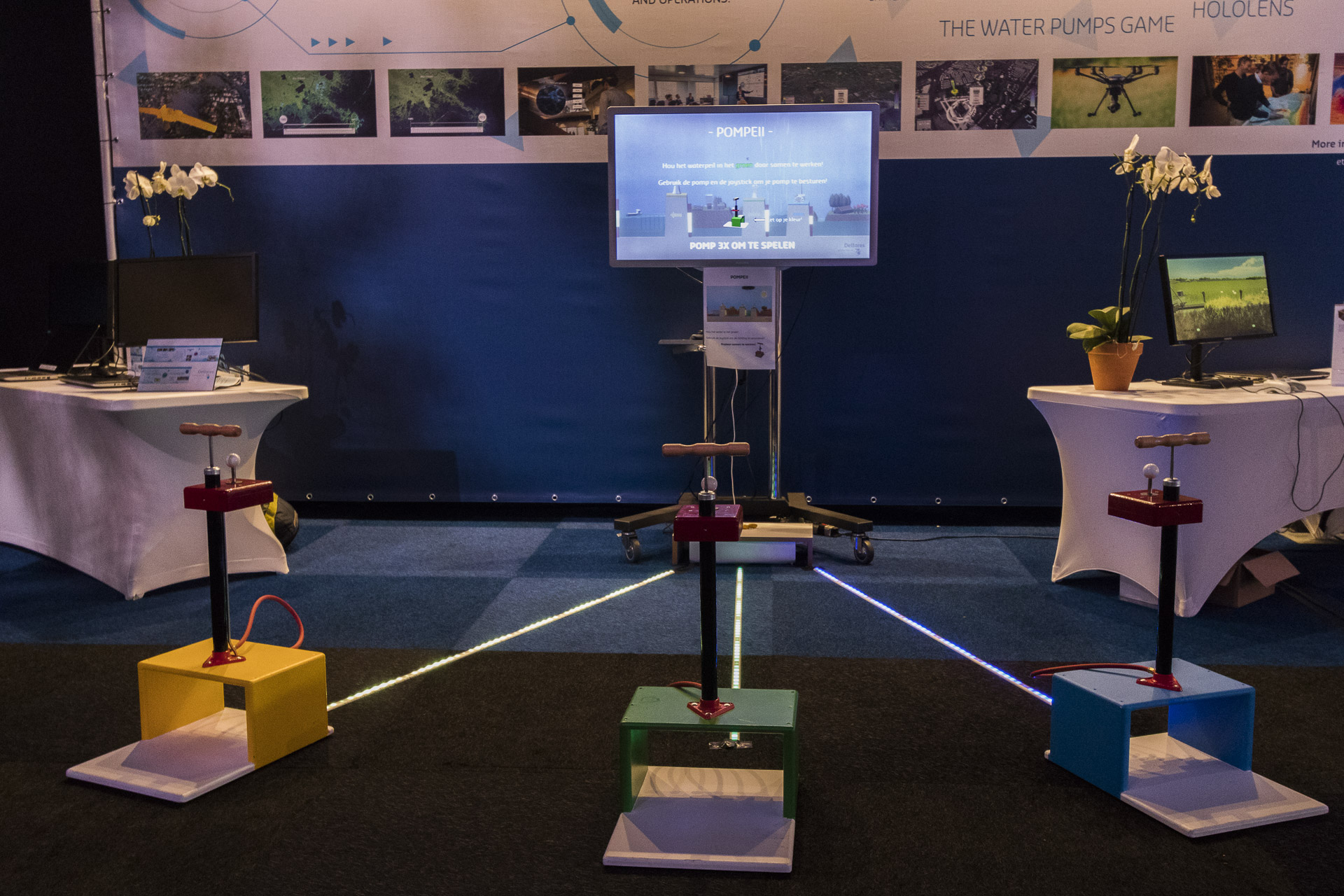
      I run a couple of sensors using MySensors in my household which send temperatures, airpressure, humidities of various rooms as well as automatic watering some plants with peristaltic pumps when a threshold has been exceeded. However, for an "open day" event at my employer I suggested to make a game involving bike pumps which will control water levels. Children (and also adults 😉) have to physically pump on the the pumps. To make everything wireless, I used the MySensors library to see if I could use it for this game. Just wanted to share this project with you and some background as it might inspire someone else to make something fun!

      alt text

      So how does it work?

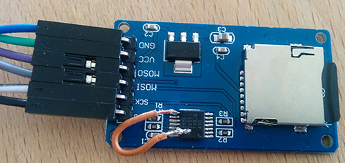
      An Arduino Pro Mini (3.3v) , NRF24l01, a joystick (configured to be two-directional), a 18650 battery holder+regulator for 3.3v, and microphone (MAX9814) are inside each pump. The bike pump's tube is actually going inside the box with the microphone. Using Arduino code the microphone is looking for certain threshold (peak) volume for a et amount of time... When the bike pump goes "psssh" 😄 this threshold is exceeded and some custom data is send to the gateway.

      Data send can be anything, but for me it was just: PlayerId|PumpDirection|Strength. Also, these "player nodes" are all wireless and you could put them anywhere 😎 . In the end the green node was closer to the TV as it started to have some connection issues for whatever reasons (could be very well my soldering and all the massive vibrations from the children being really though on these devices!!)

      Gateway is an ESP8266 (as "serial gateway") also with NRF24L01 attached and three programmable LED strips. Every time when data is received; the receive() function will dissect the input data so the appropriate LED strip can be triggered... Pumping would generate a "wave" effect in the LED strips. The direction of the pumping would also change whether the wave would go from the player or to the player.

      The ESP8266 is connected with only USB to a laptop. The game engine Unity is just processing the incoming packets directly on the serial port, and splitting the incoming data, etc:

      3;0;1;0;23;1|0|123

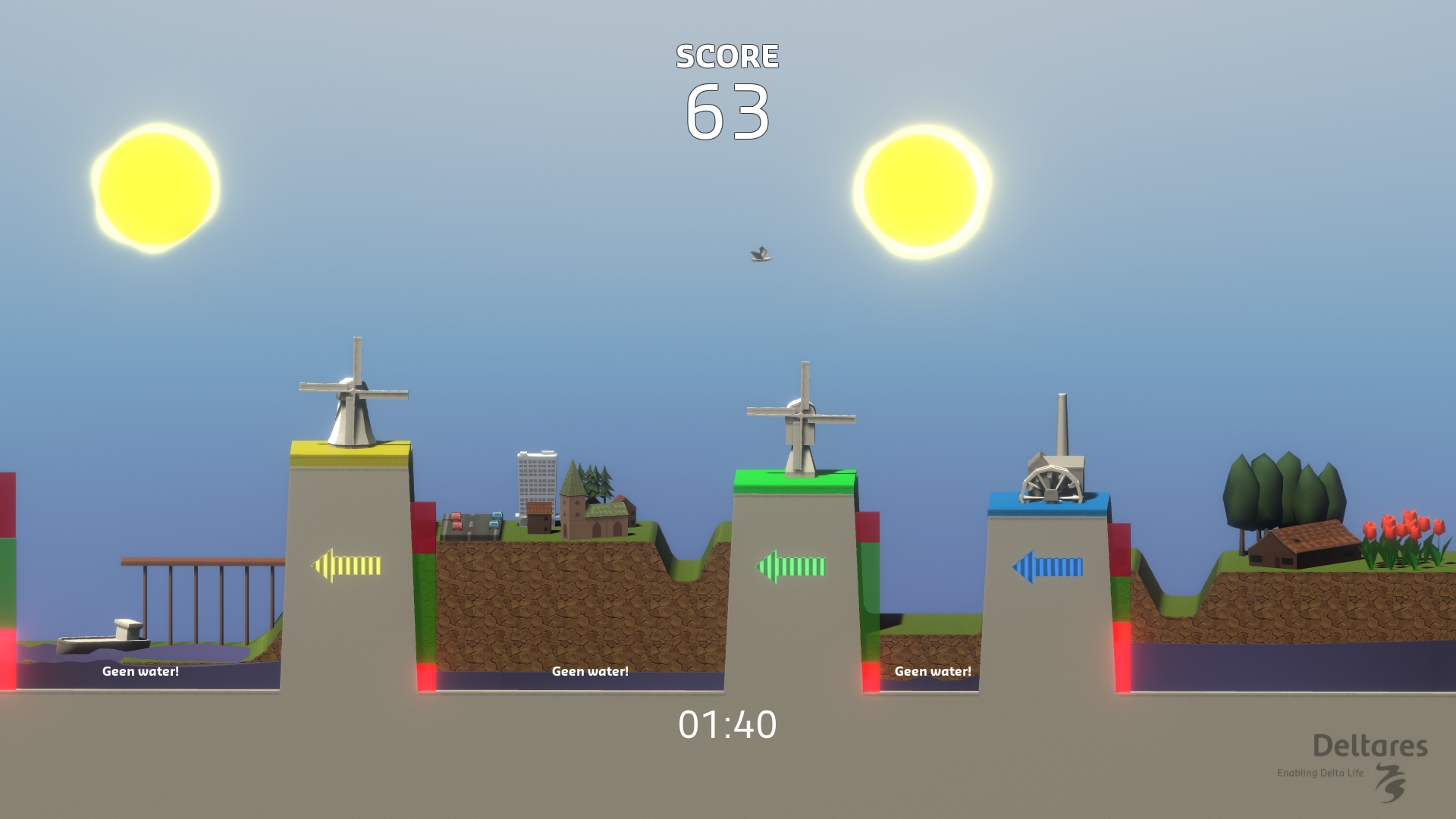
      which would be: Player 1, Direction 0, Strength 123. It would even ignore the rest of the standard MySensors information as I really didn't care and only would allow packets which would result in three values anyway. So that would trigger the "pump" in the game... either one of the two windmills or the steam pump.

      alt text

      Now, I can guarantee that the result was a lot of excited children - and adults - that were... pumped 💪 to get going! I noticed one of the holes on top of the bike pump got quite a bit larger! However I do not really feel like putting photos online these days with people (especially children) I do not know.

      In total 153 games of 2 minutes were played in 6.5h time! 😃

      posted in My Project
      Kokosnoot
      Kokosnoot
    • Powering ESP8266 / NRF24L01 repeater through USB (improvement)

      Hi,

      Here some information that might help some people. I have been using MySensors for many years now, and often struggled with some connectivity issues: Mostly due to concrete, and I also think due to the P1 port updates take a moment to upload online (even with a custom gateway which keeps the HTTP connection open, etc.)

      Recently my "old" NodeMCU gateway just failed, apparently a bit too much pressure on the USB cable and after 1.5 years of service in a new spot, it just broke the connector (obviously during a long weekend away ☺)

      As it was the last one of that type (LoLin NodeMCU 1.0), I decided to use some other equipment. Also, I wanted to make a simple "MySensors doctor" which just sends packets and gets something back - so much less functionality than the version described here: https://forum.mysensors.org/topic/9178/nrf24doctor

      So while testing the new gateway, I also noticed that my ESP8266 Wemos/NodeMCU repeater was just behaving poorly. Tried various power supplies and multiple NRF24 modules.

      After reading mixed opinions about powering through USB and the 3v3 pins of the NodeMCU, I decided just to try and build a very simple separate "power supply" using the following parts:

      USB to DIP connector (https://www.google.com/search?q=usb+to+dip&client=firefox-b-d&source=lnms&tbm=isch these with 4 pins)
      a big capacitor (my one is 670uF?) and smaller capacitor (10 uF)
      a 3.3v step down module (something which can handle 5v and bring it to 3.3v). I used: https://www.aliexpress.com/item/1005002610674227.html?spm=a2g0o.order_list.0.0.21ef1802d20uHi

      alt text

      I put these together as shown in the image in an very experimental setup... and now power the radio module from the 3v3 from the regulator, and the ESP8266 from the "stabilized" 5v supply (through the vIn pin). The change in performance has been absolutely phenomenal. Nodes Instantly connect to the repeater (quite some concrete away) and also my "mySensors doctor" suddenly reports way better connectoins: a lot of the radio modules which I considered non functional (fakes) seem to work instantly. No additional PAR requests - just instantly!

      Now, sample size is just one here.. but for me this conversion really paid of and now also considering to make similar adaptions to the gateway (which is now a ESP32, experimenting with double threading for P1 from electricity meter and gateway separate, to have less interference from the P1 every second... already wrote that code, just need to connect again some wires at the power meter.) - and more important: running on the USB port of the firewall 🙂.

      Hope it's not too much rambling. For me it really paid of, and has been such a simple yet great improvement that I would recommend others that have issues to try it too.

      posted in My Project
      Kokosnoot
      Kokosnoot
    • RE: Trying to design MySensors PCB / Fritzing

      @sundberg84 said in Trying to design MySensors PCB / Fritzing:

      @kokosnoot MySensors kicad library: https://github.com/mysensors-kicad

      I managed to install that one with a bit of effort last weekend. 👌 😃

      However, inspired by bgunnarb I am already trying again for 40minutes to get a DHT11 footprint properly working, but failing thus far. There seems to be some in: https://github.com/KiCad/kicad-footprints/tree/master/Sensor.pretty but KiCad does not appreciate that as a library, (the default is to work from github.com/kicad/Capacitors_SMD.pretty for example, but those are all archived pages)

      I manually tried adding https://github.com/KiCad/kicad-footprints/tree/master/Sensor.pretty - similar as the other libraries (type Github, etc) but just get a "ZIP error"... Maybe I should try a nightly build instead of the stable 5.0.2.

      Edit: Just got it to work by downloading the entire 5.1.0 footprint library locally, and pointing to the [..]\footprints\Sensor.pretty file. Inspired by someone else with the same issue: https://forum.kicad.info/t/personal-footprints-via-on-demand-github-plugin-error-reading-zip-local-header/11777 😃. Hopefully this info might help someone else at some point!

      posted in Hardware
      Kokosnoot
      Kokosnoot
    • RE: [SOLVED] NodeMCU ESP8266 and SPI with NRF24L01 + SD card module - sanity errors?

      Re: NodeMCU ESP8266 and SPI with NRF24L01 + SD card module - sanity errors?

      Separate reply just for searching purposes:

      It worked :-)! Now it's working perfect without changing a single line of code or changing wires. I took the risk of destroying the module, but otherwise it's useless anyway for my project. I managed to use a knife to take a few mm's of pin 13 up and then to solder a wire to pin 8 and pin 13. As described in the linked topic.

      0_1493305335364_sdcardfix.jpg

      My SD backup system one step closer! 😄

      posted in Troubleshooting
      Kokosnoot
      Kokosnoot
    • Some sensors permanently fail after one/two years

      Hi,

      I have noticed that some of my sensors are permanently "dead" after a while. I use the Easy MySensors PCB with two AAs. At some point they stop sending. Then, trying new 100% fresh AAs - of different brands - still will only give one moment a red light on the Arduino Pro Mini module (the usual "connecting to gateway" moment) and then nothing will happen.

      This happened with the sensors underneath the house (worst place of all to do debugging ;). Hence I do not have any logs yet) and also coincidentally a sensor in a friends house (~200km way) also failed permanently yesterday.

      I tried to search the forum, and found one similar situation here: https://forum.mysensors.org/topic/11949/sudden-dead-node-and-consequent-tsm-fpar-no-reply/4

      I will go underneath the house coming weekend (again) to try different nrf24l01 modules and probably also some Arduinos with the same firmware. The boards are heavily wired up to sensors, so prefer not to disconnect all the wires.

      But, I was wondering if there have been more of these cases? Is it really caused by cloned Arduino/radio modules? 🙂. I have already a pending order for a couple of (supposedly) authentic modules, curious to try those when they arrive.

      (Apologies for not having any debug logs yet, but it is not really desirable to bring a laptop below the house with very limited crawling space and lots of dust)

      posted in Troubleshooting
      Kokosnoot
      Kokosnoot