Skip to content
  • MySensors
  • OpenHardware.io
  • Categories
  • Recent
  • Tags
  • Popular
Skins
  • Light
  • Brite
  • Cerulean
  • Cosmo
  • Flatly
  • Journal
  • Litera
  • Lumen
  • Lux
  • Materia
  • Minty
  • Morph
  • Pulse
  • Sandstone
  • Simplex
  • Sketchy
  • Spacelab
  • United
  • Yeti
  • Zephyr
  • Dark
  • Cyborg
  • Darkly
  • Quartz
  • Slate
  • Solar
  • Superhero
  • Vapor

  • Default (No Skin)
  • No Skin
Collapse
Brand Logo
liningerL

lininger

@lininger
About
Posts
27
Topics
5
Shares
0
Groups
0
Followers
0
Following
0

Posts

Recent Best Controversial

  • Battery Powered Motion Sensor
    liningerL lininger

    @bjornhallberg said:

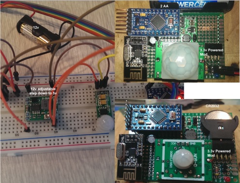
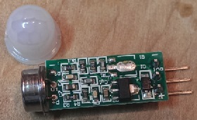
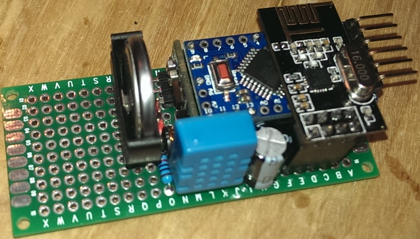
    I have no step-up in the circuit, just 2xAA that powers the NRF24 directly and then the HC-SR501 is powered from the Arduino Pro Mini, not grounded next to the RAW pin but it seems to work anyway. No idea at what voltage the HC-SR501 will start to experience problems but I guess we'll find out as the battery level drops.

    Are the 2xAA that power the NRF24 also powering the Pro Mini or are you using another power source?
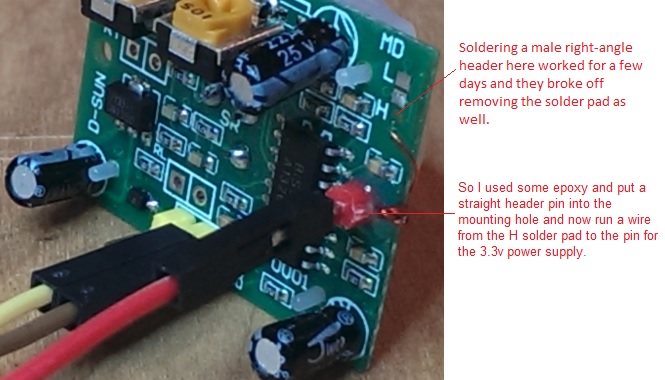
    Are you running the HC-SR501 in its 4.5v mode or the 3.3v modification?

    I believe it was the step up converter in my case as it has been 3 days, working fine, and the 2-AA's still report 3.3v when not connected to the sensor.

    Thanks

    Hardware

  • Logic Analyzer - oscilloscope
    liningerL lininger

    I ordered and received the following parts to build my own oscilloscope using an Arduino.

    http://www.instructables.com/id/Make-an-Oscilloscope-Using-the-SainSmart-Mega2560-/?ALLSTEPS

    I have never used one before so I am learning, and I can always use the arduino and touch screen for other projects like the
    Scene Controller [Preview] here.

    http://forum.mysensors.org/topic/446/scene-controller-preview

    Hardware

  • Battery Powered Motion Sensor
    liningerL lininger

    @bjornhallberg said:

    Can you check if the sensor is actually sleeping reliably between interrupts/timers

    Yep it is sleeping correctly. I output the trigger event to the console when testing locally and it only triggers on motion detect (1) and motion timeout (0) and when I exit sleep with a (0) I send the battery level back to the gateway when I exit sleep mode.

    I just replaced the DC/DC Input 0.8-3V, Output 3.3V. Step Up Power Converter - it was outputting 5v. The last batch of 5 DC/DC Input 0.8-3V, Output 3.3V I ordered 3 had 5v output and 2 had 3.3v output. I am surprised it did not fry the pro mini as I bypass the regulator. Maybe this will fix my battery drain issue.

    Be sure to check the components you get from china to make what you get is what you ordered.

    Hardware

  • Battery Powered Motion Sensor
    liningerL lininger

    @bjornhallberg said:

    And you're not getting a ton of false positives from the sensor either I take it? Can you check if the sensor is actually sleeping reliably between interrupts/timers (even if it isn't detecting motion / HIGH)?

    3.3v modification of the HC-SR501. No floating, just make sure you run the HC-GND to the Arduino-GND close to the RAW Pin (I read about this somewhere on this board I believe). If I placed the HC-GND at any other point (including the Arduino-GND next to pin 2) the HC-OUT would float all over the place. Also allow a few seconds for the sensor to settle after applying power.

    Hardware

  • Battery Powered Motion Sensor
    liningerL lininger

    @bjornhallberg

    I am using the following sleep time

    unsigned long SLEEP_TIME = 1800000; // Sleep time between wakeup and voltage reporting (in milliseconds)

    // Sleep until interrupt comes in on motion sensor. Send update every thirty minutes
    gw.sleep(INTERRUPT,CHANGE,SLEEP_TIME);

    Hardware

  • Battery Powered Motion Sensor
    liningerL lininger

    Has anyone successfully assembled a battery motion sensor that lasts for more than a few days, before the batteries are drained?

    If so could you please provide a list of components you used.

    Components I have tried in may combinations:

    Arduino Pro Mini 3.3V http://www.ebay.com/itm/200914924969
    LED and regulator removed

    NRF24L01+ http://www.ebay.com/itm/170819069271
    with CAP

    DC/DC Input 0.8-3V, Output 3.3V. Step Up Power Converter http://www.ebay.com/itm/231083181020
    LED removed

    HC-SR501 PIR Motion Sensor Module http://www.ebay.com/itm/310574919531
    5v and 3.3v power mod

    Mini PIR Motion Sensor Module http://www.ebay.com/itm/221073558145
    5v

    DC/DC Input 1-5V, Output 5V. Step Up Power Converter http://www.ebay.com/itm/400528583414
    LED removed

    Supper mini 3A DC-DC Converter Step Down buck adjustable http://www.ebay.com/itm/201073184133?ssPageName=STRK:MEWNX:IT&_trksid=p3984.m1497.l2649

    Power Sources:
    23AE battery powered
    CR2032 battery powered
    2-AA batteries powered

    motion.jpg

    Hardware

  • TIP: Remove instead of cut the track for the power LED and Regulator
    liningerL lininger

    I logged into to ask to ask this very question. The batch of mini pros I just received are also wired differently, trashed a sensor as well. On the second one I removed the LED and it still worked, but was scared to remove the regulator, without asking first. Will give it a try tonight.

    thanks for the info

    Hardware

  • DIY 1" Blind Tilting Sketch
    liningerL lininger

    @thumper

    I am not sure about LiPo and Solar or battery power in general. I had to use two separate 5v power supplies, one for the Arduino and one for the servo. Otherwise the pro mini would reset once the servo kicked in to open/close the blinds. My sketch never sleeps it always listens for commands sent from the Vera, either manually or PLEG commands at dawn and dusk.

    Hardware List
    1 - Arduino Mini Pro v3.3
    1 - 220uF Capacitor (NRF24 across 3v and GND 16v+ rating)
    1 - 470uF Capacitor Optional (Servo across 5v and GND 16v+ rating)
    1 - Servo (Micro 25.0 oz-in [1.80 kg-cm] minimum) for selectblinds.com 1" Faux Wood Blinds 43"x38"
    1 - NRF24L01 Wireless Transceiver Module (flat or antenna version) Beaware of power limitations when using the NRF24L01 antenna with LNA+PA
    1 - Kimbrough Internal Rotary Drive Control System 500 NIB - connects servo to blind rod (may differ for you blind type and servo used) http://www.ebay.com/itm/291084936296?ssPageName=STRK:MEWAX:IT&_trksid=p3984.m1423.l2649
    1 - DC power supply you may need to step-up or step-down for the servo 5v and 3.3v for the NRF depending on the Arduino board you use
    http://www.ebay.com/itm/321408108698?ssPageName=STRK:MEWNX:IT&_trksid=p3984.m1439.l2649 is the one I used to power Arduino and servo separately.

    If you are successful with LiPo and Solar combination, let us know, as it would be nice no to have the power wires hanging.

    Thanks

    My Project tilt 1.4b1 blinds

  • DIY 1" Blind Tilting Sketch
    liningerL lininger

    @naveen
    The first blind I put together I used a tinkerkit micro servo along with a Kimbrough Internal Rotary Drive Control System kit. The coupler fit perfect with the servo gear head.

    http://www.mouser.com/ProductDetail/Arduino/T010050/?qs=gMoqXxk//5Y%252bHGmjFFrUpg==

    http://www.ebay.com/itm/291084936296?_trksid=p2060778.m1438.l2649&ssPageName=STRK%3AMEBIDX%3AIT

    The second blind I put together I used a TowerPro SG90 9G micro servo and had to do some DIY modifications using epoxy to attached the coupler to one of the servo arms as the Kimbrough kit did not mesh with the SG90 teeth.

    TinkerServo.jpg

    My Project tilt 1.4b1 blinds

  • DIY 1" Blind Tilting Sketch
    liningerL lininger

    Yes I use a VeraLite and a mySensors Ethernet Gateway. I also use the Program Logic Event Generator and Day or Night plugins for Vera to control when the blinds open and close. Attached is a snapshot of the PLEG inputs, conditions and actions I have setup for controlling the blinds.
    blinds.jpg

    My Project tilt 1.4b1 blinds

  • Relaying node
    liningerL lininger

    Is this 20 communication misses still valid in the 1.4 framework? If it is could this could value be variable controlled via a #define variable in future releases? I move my sensors around and to always wait for 20 communication failures on sensor that poll once an hour is painful.

    Thanks

    Troubleshooting

  • 1.4 Beta
    liningerL lininger

    @hek Any tips on upgrading the June 1.4b1 to the August 1.4b1. I just attempted it with disastrous results. :)

    I started off.

    1. Uploading the Vera files
    2. Re-compiled the new gateway (after changing the my IP Address and such)
    3. Re-complied the Repeaters

    Just to get going. Both repeaters failed at startup with the standard FAIL in the debug logs. Wiping the Eeprom and trying again did not work. Dropping the repeaters for vera and re-including did not work? Finally went back to the June build and restored the vera from last night and then two other units failed to come back online. Had to replace the antennas on those two units to get them back on-line – BIZARRE.

    1. Do all the sensors have to be updated at once?
    2. Will existing sensors under the June 1.4b1 build co-exist with the August 1.4b1 Gateway build?
    3. Can we just recompile our existing June sketches under the new mySensors library as long as no compile errors show?

    Thanks

    Announcements 1.4beta help

  • Frustration ??
    liningerL lininger

    No I had not seen them before, Just ordered a couple. Thanks for the link.

    Enclosures / 3D Printing

  • Frustration ??
    liningerL lininger

    Cases that take into account a NRF2401+ are non existent.

    I finally moved my ethernet gateway from breadboard to a case. After looking for months for a case I finally settled on this one.

    http://www.crispconcept.com/product-p/ar-uno-e-tr.htm

    No glue or screws required it snaps together and can be easily taken apart. I ordered the one that holds the UNU R3, and Wiznet Ethernet Shield. The a NRF2401+ LNA & PA Antenna version also fit nicely into the box, but did have to drill a hole for the antenna.

    Gateway-8.jpg Gateway-7.jpg Gateway-6.jpg Gateway-5.jpg Gateway-4.jpg Gateway-3.jpg Gateway-2.jpg Gateway-1.jpg

    Enclosures / 3D Printing

  • HC-SR501 motion sensor
    liningerL lininger

    @Bandra said:

    Does anybody who has bypassed the onboard regulator on the HC-SR501 be able to post up a photo of where you soldered?

    Here is how id modified the sensor.

    Motion 3v modify.jpg

    Does anyone know if the Mini version also has such a place as the SR501?

    Motion Mini.jpg

    Hardware

  • Power conservation with battery powered sensors
    liningerL lininger

    It has been about 2 weeks since I put two temperature sensors in an attic placement, with 2AA Alkaline and they are both reporting 100% battery life – so I am hopeful they will last a while.

    I just put together a DHT11 Sensor with a CR2023 v3.3 Lithium battery. Anybody using this type of battery or have any experience with how long they might last, with a wake up once per hour? Regulator trace was cut and the led removed from the 3.3v pro mini.

    Thanks
    CoinBattery.jpg

    Hardware battery

  • DIY case idea
    liningerL lininger

    @Yveaux It's the Temp Sensor. All I had were the waterproof ones.

    Enclosures / 3D Printing pvc case

  • DIY case idea
    liningerL lininger

    Trying to find a case for my battery temperature sensor, I noticed my Netatmo sitting on the shelf. Found some 1.25” PVC piping laying around. The 3cm x 7cm green PCB boards fit perfectly inside as does the double battery case. Spray it with some stainless steel (or any color) paint.

    Still need to find some end caps. Something like http://www.amazon.com/FORMUFIT-1-1-PVC-Internal-Domed/dp/B003VLB0J0/ref=sr_sp-atf_title_4_65?ie=UTF8&qid=1406504800&sr=8-65&keywords=FORMUFIT

    case idea.jpg

    Enclosures / 3D Printing pvc case

  • DIY 1" Blind Tilting Sketch
    liningerL lininger

    I have finally finished the automation of two blinds to tilt open at sunrise and tilt closed at sunset. I have updated an earlier sketch so it now works with the latest mySensors 1.4b1 beta library. Once the power related issues were worked out (See discussion in http://forum.mysensors.org/topic/182/standard-versus-lna-pa-radio-modules) they have been operating flawlessly for the last several weeks using the 1.4b1 library. Kudos to the MySensors team, you guys have done a great job!

    I have attached the sketch, if anyone is interested in it. It’s not perfect and can always be improved, but it was a great learning project and might help someone just starting out with mySensors. The sketch is heavily commented with lots of debug printing, so you see how the processes interact. Be sure to comment out this line #define PDEBUG 1 for a final build. I also attached a snapshot of the process I followed while working on the project.

    Have Fun
    Blinds_Sensor _Design_Steps.jpg
    myBlinds40.ino

    My Project tilt 1.4b1 blinds

  • Power conservation with battery powered sensors
    liningerL lininger

    Those were the correct traces to cut for the Deek-Robot 3.3v Pro Mini.

    No power light
    No regulator (note: you will only be able to upload your sketches when only using the the FTDI adapter with the pro mini, since any radio and senors will receive no power - attach your battery power for these to receive power and be able to debug the sketch).

    Set the sketch up to sleep for 60 seconds and received temperature readings just fine. Bumped it up to 3600 seconds once per hour (as this is the target interval I am after) to see how long the battery will last.

    Hardware battery
  • Login

  • Don't have an account? Register

  • Login or register to search.
  • First post
    Last post
0
  • MySensors
  • OpenHardware.io
  • Categories
  • Recent
  • Tags
  • Popular