Skip to content
  • MySensors
  • OpenHardware.io
  • Categories
  • Recent
  • Tags
  • Popular
Skins
  • Light
  • Brite
  • Cerulean
  • Cosmo
  • Flatly
  • Journal
  • Litera
  • Lumen
  • Lux
  • Materia
  • Minty
  • Morph
  • Pulse
  • Sandstone
  • Simplex
  • Sketchy
  • Spacelab
  • United
  • Yeti
  • Zephyr
  • Dark
  • Cyborg
  • Darkly
  • Quartz
  • Slate
  • Solar
  • Superhero
  • Vapor

  • Default (No Skin)
  • No Skin
Collapse
Brand Logo
micahM

micah

@micah
About
Posts
63
Topics
8
Shares
0
Groups
0
Followers
0
Following
2

Posts

Recent Best Controversial

  • 💬 Smart Alarm Clock
    micahM micah

    Another thing that I've thought of is removing the RTC module completely since we can query the time from the server periodically.

    This would save components and pins, but it would limit the clock to only working with the controller, whereas the current design allows it to run independently

    OpenHardware.io alarm led ring light speaker domoticz mysensors clock

  • 💬 Smart Alarm Clock
    micahM micah

    The method Check_KeyPad (Line 300) handles the buttons.
    Currently my buttons do the following

    • show/program alarm
    • hour
    • minute
    • turn alarm on and off
    • turn on or off nightlight
    OpenHardware.io alarm led ring light speaker domoticz mysensors clock

  • 💬 Smart Alarm Clock
    micahM micah

    @dbemowsk
    To use a 24 hour clock switch the following bool

    bool Screen_HourFormat24 = false;
    

    I think I used the colon to signify that an alarm was set, I think I flashed it on and off. in the Update_Screen method

       if ((Alarm1_Enabled) && (!Keys_ShowAlarmOnScreen)){
          if(Screen_ClockPoint)ledScreen.point(POINT_ON);
          else ledScreen.point(POINT_OFF);
        } else
          ledScreen.point(POINT_ON);
    
    OpenHardware.io alarm led ring light speaker domoticz mysensors clock

  • 💬 Smart Alarm Clock
    micahM micah

    I often wish our fancy mysensor nRF chips only used 1 arduino wire :(

    OpenHardware.io alarm led ring light speaker domoticz mysensors clock

  • 💬 Smart Alarm Clock
    micahM micah

    I found a library online.... #include <AnalogMatrixKeypad.h>

    I made some modifications (although I can't quite remember what they were), I think about the number of buttons, or combinations, or target values.

    But generally the library provided the 1 wire, resistor ladder and debouncing functionality I needed

    OpenHardware.io alarm led ring light speaker domoticz mysensors clock

  • 💬 Smart Alarm Clock
    micahM micah

    @Nca78
    exactly correct.

    I originally went with the same resistor value so that it was easy. But then when I thought about how many button combinations I wanted (thinking about a real clock where you hold down the alarm set button then press the hour button) I went with different values.

    My implementation still isn't perfect, since I'm a bloody amateur... lol. I think 1 or 2 of the combinations I never got working.

    But for the most part it accomplished what I wanted... provided many buttons and combinations on a single input pin, since I was quickly running out of them

    OpenHardware.io alarm led ring light speaker domoticz mysensors clock

  • What did you build today (Pictures) ?
    micahM micah

    Here is a project I finished this weekend.... 5m LED strip controller (the cover is off for the photo)
    0_1508764628331_IMG_20170317_175657100.jpg

    I think you can say I've come quite far since my first ever arduino build... lol
    0_1508764679200_2016-02-09-21h05m49-[DSC_0001].jpg

    General Discussion

  • RGB LED strip
    micahM micah

    Here is a photo of my actual device with the cover off

    0_1508763006582_IMG_20170317_175657100.jpg

    My Project

  • RGB LED strip
    micahM micah

    @maghac Great project.

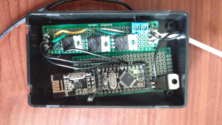
    I've made something similar, Arduino Pro Mini 5v, 5m LED strip (non-addressable), nrf24L01+ and MOSTFETs

    I know it took me awhile to find code examples, so I figured I would share my code incase it helps anyone else.

    I use Domoticz as a controller. This code talks to:

    • Switch - to control turning my color cycle fade effect on
    • Dimmer - to control the speed of the color cycle fade effect
    • RGB switch - to control having only a single color turned on and the brightness of the string.

    Much of my code is standard stuff, using FastLED analogue, but I'm particularly proud of the brightness part, since I bashed my head against the keyboard several times trying to figure it out

    //## INCLUDES ##
    #define MY_DEBUG
    #define MY_RADIO_NRF24
    #define MY_NODE_ID 20
    
    #include <MySensors.h>
    #include <SPI.h>
    #include <FastLED.h>
    
    #define cID_RGB_SELECTOR 0
    #define cID_CYCLE_EFFECT 1
    #define cID_CYCLE_EFFECT_SPEED 2
    
    #define PIN_RED   5
    #define PIN_GREEN 6
    #define PIN_BLUE  3
    
    //## VARIABLES ##
    // MySensors
    #define MySensors_SketchName      "RGB LED Strip"
    #define MySensors_SketchVersion   "v0.3"
    MyMessage MySensors_MSG_Last_Color(cID_RGB_SELECTOR,V_VAR1);
    MyMessage MySensors_MSG_RGB_Selector(cID_RGB_SELECTOR, V_LIGHT);
    MyMessage MySeonsors_MSG_CYCLE_EFFECT(cID_CYCLE_EFFECT, V_LIGHT);
    MyMessage MySensors_MSG_CYCLE_EFFECT_SPEED(cID_CYCLE_EFFECT_SPEED, V_DIMMER);
    bool MySensors_RequestACK = false;
    // Single color
    int Solid_RGB_Active=0;
    char Solid_RGB_Color[] = "000000";
    uint16_t Solid_RGB_Brightness = 0xFF;
    // Cycle effect
    int Cycle_Effect_Active=0;
    unsigned long Cycle_Effect_pMillis = 0;
    long Cycle_Effect_Speed = 20;
    static uint8_t Cycle_Effect_Current_Hue;
    // Supporting
    bool Status_Change = false;
    bool Print_Debug = false;
    
    // ## Primary flow control
    void setup() {
      Serial.begin(115200);
      while (!Serial) ;
      Serial.print("compiled: ");Serial.print(__DATE__);Serial.println(__TIME__);
    
      pinMode(PIN_RED,   OUTPUT);
      pinMode(PIN_GREEN, OUTPUT);
      pinMode(PIN_BLUE,  OUTPUT);
    
      Event_ColorTestBars();
    
      request(cID_RGB_SELECTOR, V_VAR1);
      request(cID_RGB_SELECTOR, V_LIGHT);
      request(cID_CYCLE_EFFECT, V_LIGHT);
      request(cID_CYCLE_EFFECT_SPEED, V_DIMMER);
    }
    void loop() {
      if (Cycle_Effect_Active == 1){
        unsigned long currentMillis = millis();
        Event_RunCycleEffect(currentMillis);
      } else if (Status_Change){
        Status_Change = false;
          #ifdef MY_DEBUG
            if (Print_Debug) {Serial.println("STATUS CHANGE");}
          #endif
        if (Solid_RGB_Active == 0){
          Event_SetLEDColors( CRGB::Black );
        }else if (Solid_RGB_Active == 1){
          CHSV colorHSV = rgb2hsv_approximate(str2CRGB(Solid_RGB_Color));
          Event_SetLEDColors(CHSV(colorHSV.h, colorHSV.s, Solid_RGB_Brightness));
        }
      }
    }
    // ## MySensors Methods
    void presentation()  {
      sendSketchInfo(MySensors_SketchName, MySensors_SketchVersion);
    
      present(cID_RGB_SELECTOR, S_RGB_LIGHT, "RGB Color Selector", MySensors_RequestACK);
      present(cID_CYCLE_EFFECT, S_LIGHT, "RGB Cycle Effect", MySensors_RequestACK);
      present(cID_CYCLE_EFFECT_SPEED, S_DIMMER, "RGB Cycle Effect Speed", MySensors_RequestACK);
    }
    void receive(const MyMessage &message){
      #ifdef MY_DEBUG
        if (message.isAck()){
          Serial.println("Got ack from gateway");
        }
      #endif
      if (message.type == V_LIGHT){
        #ifdef MY_DEBUG
          if (Print_Debug) {Serial.println("message v_light");}
        #endif
        int current_Light_State = message.getString()[0] == '1';// Incoming on/off command sent from controller ("1" or "0")
        if (message.sensor==cID_CYCLE_EFFECT){// is Cycle Message
          if (current_Light_State==1){//turn cycle on
            Event_LightCycle(true, true, false);
            Event_SolidColor(false, false, true);
          } else {//turn cycle off
            Event_LightCycle(false, true, false);
            Event_SolidColor(false, false, true);
          }
        } else if (message.sensor==cID_RGB_SELECTOR){// is RGB Message
          if (current_Light_State==1){//turn RGB on
            Event_SolidColor(true, true, false);
            Event_LightCycle(false, false, true);
          } else {//turn RGB off
            Event_SolidColor(false, true, false);
            Event_LightCycle(false, false, true);
          }
        } else {
          #ifdef MY_DEBUG
            Serial.print("UNKNOWN Light - Message:");
            Serial.print(message.getString());
            Serial.print(" - Sensor:");
            Serial.println(message.sensor);
          #endif
        }
      } else if (message.type == V_RGB){
        #ifdef MY_DEBUG
          if (Print_Debug) {Serial.println("message v_rgb");}
        #endif
        String szMessage=message.getString();
        strcpy(Solid_RGB_Color, getValue(szMessage,'&',0).c_str());
        Solid_RGB_Active = 1;
      }else if (message.type == V_DIMMER) {// if DIMMER type, adjust brightness
        #ifdef MY_DEBUG
          if (Print_Debug) {Serial.println("message v_dimmer");}
        #endif
        if (message.sensor==cID_RGB_SELECTOR){// is single Message
          if (Solid_RGB_Active==1){//turn RGB on
            Event_SolidColor(true, true, false);
            Event_LightCycle(false, false, true);
          } else {//turn RGB off
            Event_SolidColor(false, true, false);
            Event_LightCycle(false, false, true);
          }
          Solid_RGB_Brightness = map(message.getLong(), 0, 100, 0, 255);
          CRGB colorRGB = str2CRGB(Solid_RGB_Color);
          CHSV colorHSV = rgb2hsv_approximate(colorRGB);
          colorHSV = CHSV(colorHSV.h, colorHSV.s, Solid_RGB_Brightness);
          Event_SetLEDColors(colorHSV);
          #ifdef MY_DEBUG
            if (Print_Debug) {
              Serial.print("colorHSV.h:");
              Serial.println(colorHSV.h);
              Serial.print("colorHSV.s:");
              Serial.println(colorHSV.s);
              Serial.print("colorHSV.v:");
              Serial.println(colorHSV.v);
            }
          #endif
          Event_SendLastColor();
        } else if (message.sensor==cID_CYCLE_EFFECT_SPEED){// is Speed dimmer Message
          Cycle_Effect_Speed = map(message.getLong(), 0, 100, 1, 202);
          #ifdef MY_DEBUG
            if (Print_Debug) {
              Serial.print("Cycle_Effect_Speed: ");
              Serial.println(Cycle_Effect_Speed);
            }
          #endif
        }
      }else if (message.type == V_STATUS) {           // if on/off type, toggle brightness
        #ifdef MY_DEBUG
          if (Print_Debug) {Serial.println("message v_status");}
        #endif
        Solid_RGB_Active = message.getInt();
        Cycle_Effect_Active = 0;
        if (Solid_RGB_Active == 0){
          if (Print_Debug) {Serial.println("Strip OFF");}
          Event_SetLEDColors( CRGB::Black );
        }else{
          if (Print_Debug) {Serial.println("Strip ON");}
          Event_SetLEDColors(strtol(Solid_RGB_Color, NULL, 16));
        }
        //Event_SendLastColor();
      }else if (message.type==V_VAR1) {            // color status
        String szMessage=message.getString();
        #ifdef MY_DEBUG
          if (Print_Debug) {
            Serial.println("message v_var1");
            Serial.println(szMessage);
          }
        #endif
        strcpy(Solid_RGB_Color, getValue(szMessage,'&',0).c_str());
        Solid_RGB_Active = 1;
        Cycle_Effect_Active = 0;
      }
      Status_Change = true;
    }
    // ## Events
    void Event_LightCycle(bool t, bool s, bool u) {
      Cycle_Effect_Active = (t) ? 1 : 0;
      if (u){
        send(MySeonsors_MSG_CYCLE_EFFECT.set(Cycle_Effect_Active),MySensors_RequestACK);
      }
    }
    void Event_SolidColor(bool t, bool s, bool u) {
      Solid_RGB_Active = (t) ? 1 : 0;
      if (u){
        send(MySensors_MSG_RGB_Selector.set(Solid_RGB_Active),MySensors_RequestACK);
      }
    }
    void Event_SetLEDColors( const CRGB& rgb){
      analogWrite(PIN_RED,   rgb.r );
      analogWrite(PIN_GREEN, rgb.g );
      analogWrite(PIN_BLUE,  rgb.b );
    }
    void Event_SendLastColor(){
      String current_status=Solid_RGB_Color+String("&")+String(Solid_RGB_Brightness)+String("&")+String(Solid_RGB_Active);
      send(MySensors_MSG_Last_Color.set(current_status.c_str()),MySensors_RequestACK);
    }
    void Event_RunCycleEffect(unsigned long theMills){
      if (theMills - Cycle_Effect_pMillis >= Cycle_Effect_Speed){
        Cycle_Effect_pMillis = theMills;
        Cycle_Effect_Current_Hue = Cycle_Effect_Current_Hue + 1;
        Event_SetLEDColors( CHSV( Cycle_Effect_Current_Hue, 255, 255) );
      }
    }
    void Event_ColorTestBars(){// Event_ColorTestBars: flashes Red, then Green, then Blue, then Black. Helpful for diagnosing if you've mis-wired which is which.
      Event_SetLEDColors( CRGB::Red );   delay(500);
      Event_SetLEDColors( CRGB::Green ); delay(500);
      Event_SetLEDColors( CRGB::Blue );  delay(500);
      Event_SetLEDColors( CRGB::Black ); delay(500);
    }
    // ## Helper Functions
    String getValue(String data, char separator, int index){
     int found = 0;
      int strIndex[] = {0, -1};
      int maxIndex = data.length()-1;
      for(int i=0; i<=maxIndex && found<=index; i++){
        if(data.charAt(i)==separator || i==maxIndex){
          found++;
          strIndex[0] = strIndex[1]+1;
          strIndex[1] = (i == maxIndex) ? i+1 : i;
        }
      }
      return found>index ? data.substring(strIndex[0], strIndex[1]) : "";
    }
    int x2i(char *s) {
      int x = 0;
      for(;;) {
        char c = *s;
        if (c >= '0' && c <= '9') {
          x *= 16;
          x += c - '0';
        }else if (c >= 'A' && c <= 'F') {
          x *= 16;
          x += (c - 'A') + 10;
        }else {
          break;
        }
        s++;
      }
      return x;
    }
    char* str2char(String command){
        if(command.length()!=0){
            char *p = const_cast<char*>(command.c_str());
            return p;
        }
    }
    CRGB str2CRGB(String s){
      String r = str2char(s.substring(0,2));
      String g = str2char(s.substring(2,4));
      String b = str2char(s.substring(4,6));
      uint8_t red = x2i(r.c_str());
      uint8_t green = x2i(g.c_str());
      uint8_t blue = x2i(b.c_str());
      #ifdef MY_DEBUG
        if (Print_Debug) {
          Serial.print("r:");
          Serial.println(r);
          Serial.print("g:");
          Serial.println(g);
          Serial.print("b:");
          Serial.println(b);
          Serial.print("red:");
          Serial.println(red);
          Serial.print("green:");
          Serial.println(green);
          Serial.print("blue:");
          Serial.println(blue);
        }
      #endif
      CRGB colorRGB = CRGB(red, green, blue);
      return colorRGB;
    }
    

    Hopefully this proves useful to someone :)

    My Project

  • 💬 Smart Alarm Clock
    micahM micah

    Hey everyone.

    Sorry, had a computer crash and file loss issue a few months ago.

    I can't find my final code file, but I did find an older version (incomplete) called ClockRebuild.ino and I uploaded it to the project.

    Hopefully that helps

    One day I'll come back and truly finish this project, life just keeps getting in the way

    OpenHardware.io alarm led ring light speaker domoticz mysensors clock

  • RGB LED strip controller with FastLED
    micahM micah

    @gohan maybe, I don't know, I only pretend to be an electrical engineer in my spare time... Lol

    My Project

  • RGB LED strip controller with FastLED
    micahM micah

    Yeah I usually use some 78xx variant

    My Project

  • Hacking a remote control Hunter ceiling fan controller
    micahM micah

    I'm actually working on something similar right now. I also ripped apart my remote control.

    Originally I was planning on getting a radio transceiver set to read and then mimic the remote codes, but I couldn't get it working.

    So instead I'm in the process of connecting the remote board Frankenstein style to an arduino with transistors and stuff.

    The remote board has contact patches for all the buttons, and if you connect them to ground it triggers that specific button.

    So my final build will have the remote control board, a pro mini, nrf and other parts all cobbled together and stuck in a box on my nightstand. From there I can use my phone domoticz app to control anything.

    I'm also adding a temperature sensor so I can automatically control the fan based on room temperature.

    My Project

  • Converting a wifi outlet to an nRF24 MySensors device
    micahM micah

    It may have been this project I forked, I can't remember https://github.com/Danimal4326/homebridge-ecoplug

    My Project

  • Converting a wifi outlet to an nRF24 MySensors device
    micahM micah

    I have the same plugs (Eco Plug I think)

    I use domoticz on a raspberry pi for my mysensors and other stuff.

    I didn't hack mine, I just forked a homebridge plugin (it was either python or node based, I can't remember) and got it working on my domoticz

    My Project

  • RGB LED strip controller with FastLED
    micahM micah

    @pansen I've burned out a couple nano's and pro mini's by supplying what was supposedly 12v from a wall wart.

    So I would advise using a linear voltage regulator

    My Project

  • My basement flooding alarm
    micahM micah

    Nice build, and great idea using the ultra sonic sensor.

    This sort of thing was the exact reason I got into arduino and eventually mysensors. I had a concern about a damp basement and went looking for a water leak detection alarm but the prices were so high at the time... eventually I stumbled upon arduino and the obsession went from there.

    The first node I ever made was a water leak detection system that used the 4cm thing mentioned above... then I realized I had all these left over pins ;) so I filled them up with a gas, flame, temperature, humidity and light sensor.

    Forget nest protect and commercial water leak detection systems... I now have an all in one DIY solution that probably only cost $30

    My Project

  • Fire pit RGB striplight controller
    micahM micah

    @Boots33

    I've fried a couple pro mini's and a nano running 12v to the vin/raw... actually in one case it might have been up to 15v .... oops.

    But I've since learned my lesson.... I now use a Linear Voltage Regulator between the source and the arduino for all my builds that have a higher voltage power source (i.e.: builds that run lights). Typically a L7805CV or L7809CV or L7810CV (or other) depending on the voltage of my source and what I want to send to the arduino.

    Here is an example L7809CV from AliExpress

    My Project

  • 💬 Smart Alarm Clock
    micahM micah

    I've finally settled on an enclosure design for my first (of 3) clock. This one is for my 10 year old son, I think he's going to love it.

    I originally found this on pintrest....

    fake bomb clock
    Fake bomb clock

    I'm going to use the bomb idea but modify it to fit all my existing design elements.

    I'm currently awaiting some parts from aliexpress and I'm still trying to find materials for the dynamite sticks. Hopefully I'll have everything I need soon so I can start to build it

    OpenHardware.io alarm led ring light speaker domoticz mysensors clock

  • Pro mini
    micahM micah

    @Oitzu said:

    The RAW pin runs into the oboard voltage regulator and can be feed 3.3V - 12V (Be aware that most china clones don't withstand the full 12V)

    I can attest to this fact, since in the last few weeks I fried 3 clones building my 12v led controller before realizing they just can't handle 12v on the raw/vcc pin.

    Hardware
  • Login

  • Don't have an account? Register

  • Login or register to search.
  • First post
    Last post
0
  • MySensors
  • OpenHardware.io
  • Categories
  • Recent
  • Tags
  • Popular