Navigation

    • Register
    • Login
    • OpenHardware.io
    • Categories
    • Recent
    • Tags
    • Popular
    1. Home
    2. MikeF
    3. Best
    • Profile
    • Following
    • Followers
    • Topics
    • Posts
    • Best
    • Groups

    Best posts made by MikeF

    • Temperature / humidity node with OLED display

      I've just built this temperature / humidity node, with a 1.3" OLED display:

      TempHumDisp_1.jpg
      TempHumDisp_2.jpg

      The OLED is a 128x64 I2C version, driven by an SSD1306 chip, and will display 8 lines of text - but as I'm short-sighted 😄 , I've used double-height text, showing time (from Domoticz), temperature, humidity and battery voltage.

      The node uses a Ceech board, and is powered by a Samsung phone battery with a micro-USB connector (top left) to charge it. There is an HTU21D temperature / humidity sensor bottom left. Connectors have been judiciously bent (!), so that the base will fit on the box.

      The sketch is based on Ceech's example sketch for the board, with the inclusion of a cut-down, text-only library for the SSD1306 (to save space).

      posted in My Project
      MikeF
      MikeF
    • Multisensor node using Ceech board

      Here are some pics of my multisensor node, using the Ceech board with lithium battery charger. The stripboard houses - from left to right - a BMP180, HTU21D and BH1750FVI. As you can see, I've soldered radio and connections directly to the board, to reduce height in order to fit the box.

      IMG_1957 copy.jpg
      IMG_1958 copy.jpg
      IMG_1959 copy.jpg
      IMG_1960 copy.jpg

      The box is the same as the one shown here:
      (http://www.ebay.com/itm/85x58x33mm-Waterproof-Cover-Clear-Plastic-Electronic-Project-Box-Enclosure-CASE-/281390875149?hash=item418434020d)

      (but purchased from UK eBay website).

      I had to shave the board down by about 1-2mm on one edge, to fit the box - sorry, Ceech!

      posted in My Project
      MikeF
      MikeF
    • RGBW Controller kit

      I've been looking around for a hardware solution for an RGBW LED strip controller, and came across this from The CustomGeek. It's a full kit of parts, and is based on an ATMEGA328P with an Arduino bootloader and sketch already loaded. The board uses 4 MOSFETs for the different LED channels, and has some interesting features:

      • onboard RGB and white LEDs, which enable you to monitor the colours and levels of the LED strips
      • serial interface, with TTL and RS232 level options, giving the ability to send serial commands (such as red50, to set red to 50%)
      • an IR interface, using the Adafruit Mini Remote Controller (not included in the kit)
      • an FTDI interface, to enable the Arduino to be reprogrammed (new sketches uploaded)
      • unused analogue and digital pins brought out to a header, for easy external connection.

      As such, I thought it should be possible to 'MySensorise' this, and add an NRF24L01+ radio.

      I ordered the kit from the US (took about 2 weeks to arrive). I discovered that the board uses digital outputs 3, 9, 10 & 11, where the radio requires 9, 10 & 11. I got round this by swapping 5 & 11 on the board (cutting tracks, adding links), and changing CE & CS to 6 & 7 in the sketch. I've tried several of the RGB(W) sketches published on this site, and all work well! (I'm using Domoticz as controller.)

      I made a few other minor mods to the board:

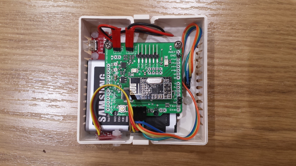
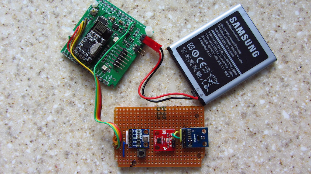
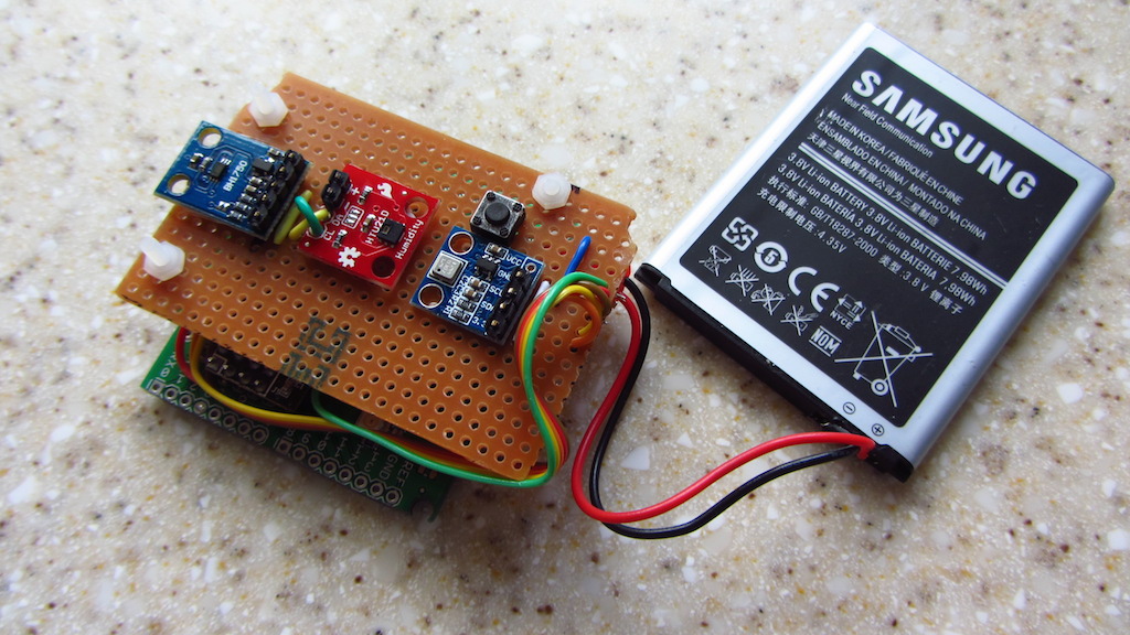
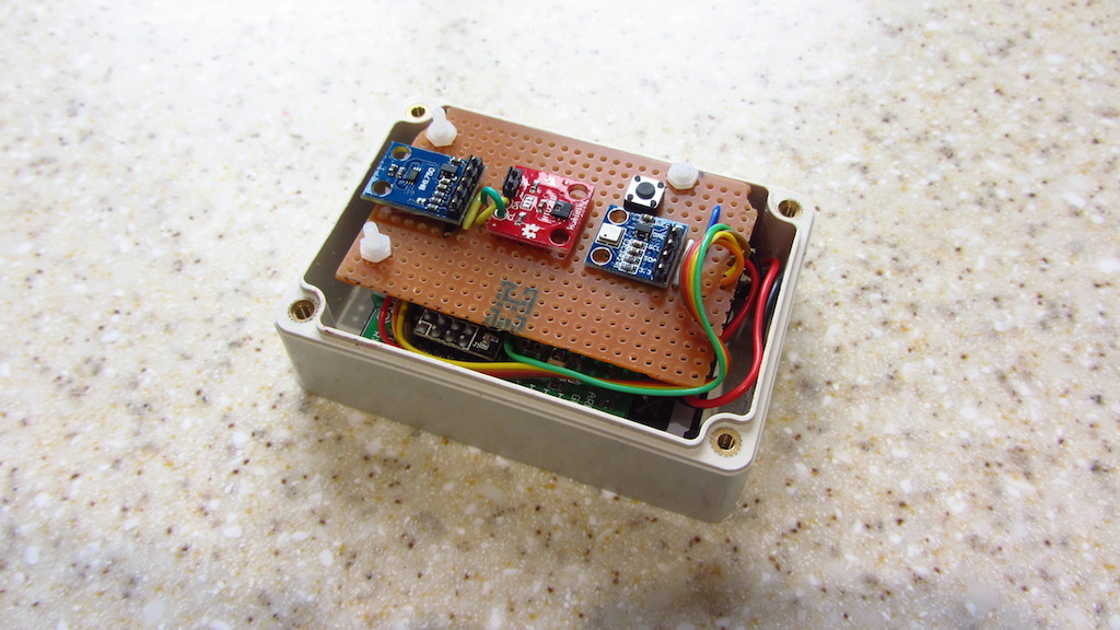
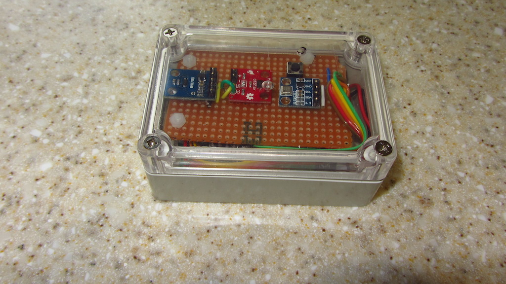
      • I built a small 'daughterboard' consisting of the radio and AMS1117 (to provide 3.3V), and used different headers to enable this to be plugged in horizontally (see pics)
      • I mounted the IR receiver on a header, so that I could use this externally from the board
      • I changed the values of the resistors driving the onboard LEDs, as the latter were too bright.

      I've included some pics below:


      I've also developed a sketch, which I'll upload in another post.

      posted in My Project
      MikeF
      MikeF
    • RE: PWM frequencies on pin 9,10,11

      I've found that adding this to setup() can cure flickering:

        //Increase Timer frequency to prevent flicker in Pins 5,6 PWM
        TCCR0A = _BV(COM0A1) | _BV(COM0B1) | _BV(WGM00); 
      
      posted in Hardware
      MikeF
      MikeF
    • RE: EU flag development board

      @ceech, could you make a version for the UK - without the flag? 😄

      posted in My Project
      MikeF
      MikeF
    • RE: RGBW Strip WireLess Shield V1.0

      What's the current capacity - and therefore max. no. of LEDs - per channel? (I guess I was expecting to see some chunky TO-220 MOSFETs!)

      posted in OpenHardware.io
      MikeF
      MikeF
    • RE: Control leds with a mosfet

      For an N-channel MOSFET such as IRLML2502, source should go to GND and drain to 12V via the LED strip, as in your diagram (I'm assuming you're using common-cathode LED strips?).

      Can you check the pinout of the MOSFET? The datasheet shows different pin numbers: IRLML2502

      posted in Hardware
      MikeF
      MikeF
    • RE: Domoticz now supports the MySensors MQTT Gateway

      Got this working OK. I built a MQTT / W5100 gateway as per the instructions in the MySensors Build section, and changed the topic prefixes and controller IP address in the example sketch.

      Initially this failed, as I had connected Vcc on the W5100 to 5V instead of 3.3V, and I had the prefixes the wrong way round (i.e., /out instead of /in).

      (BTW: I'm using MySensors 2.1.0 and Domoticz 3.6371 - latest / recent beta.)

      posted in Domoticz
      MikeF
      MikeF
    • RE: Domoticz as controller **and** a gateway for MySensor nodes running on a Raspberry Pi 2

      Hello @GertSanders, for the time being I've got the gateway working with CE connected to pin 15, having carried out some 'surgery' to the board!

      I've found this code in PiGatewaySerial.cpp (line 198 onwards):

      /* create MySensors Gateway object */
      #ifdef __PI_BPLUS
      gw = new MyGateway(RPI_BPLUS_GPIO_J8_15, RPI_BPLUS_GPIO_J8_24, BCM2835_SPI_SPEED_8MHZ, 1);
      #else
      gw = new MyGateway(RPI_V2_GPIO_P1_22, BCM2835_SPI_CS0, BCM2835_SPI_SPEED_8MHZ, 1);
      #endif

      Is this the 'offending' code?

      posted in My Project
      MikeF
      MikeF
    • RE: PCB Boards for MySensors

      Is there a 'local' source of PCBs for MySensors (i.e., UK / Europe)?

      I've just (14 November) received 3 of @sundberg84's Low Power Node PTH v2 (atmega328p and NRF24L01+) boards from OSH Park in the US, which I ordered on 24 October - panelisation and fabrication was actually quick, and they were finished and posted on 2 November. Elapsed time was 3 weeks, but I understand it can be up to twice this for boards from China (e.g., dirtypcb's).

      It would be good if there was a more local source, with shorter elapsed times.

      posted in Hardware
      MikeF
      MikeF
    • RE: RGBW Controller kit

      OK, I'm starting to understand HSV better - and I've been reading this thread. I understand that Domoticz currently (although gizmocuz states this is due to change) only allows you to change Hue and Brightness (V), but not Saturation. Is there any other way of changing all 3 values, and sending them to a MySensors RGB node (*) - e.g., using V_TEXT (with suitable conversion from HSV to RGB)?

      (* I'm currently looking at RGB, not RGBW, as I'm using a separate white strip - I've set up a simple sketch with V_RGB, and V_DIMMER for white.)

      posted in My Project
      MikeF
      MikeF
    • RE: What options are there for wireless wifi power-plugs with energy-monitoring?

      I'm using one of these : http://uk.tp-link.com/products/details/cat-5258_HS110.html

      I've written a Python script to read this in Domoticz (not MySensors though).

      posted in Hardware
      MikeF
      MikeF
    • RE: Mini Weather Station

      ... and here's mine - in white:
      alt text
      alt text
      (now managed to upload pics in portrait!)

      I'm using a BME280 instead of a BMP180 and DHT22.

      posted in My Project
      MikeF
      MikeF