Control leds with a mosfet
-
I have a forum post here where I created my own controller for analog led strips. I had some issues where my controlling pro mini died, so I tried to directly connect the 3.3V to the gate of a transistor while the led strip was connected. What happened was that the AMS1117 (where the 3.3V comes from, converted from the 12V) got very hot very fast. It seems like there is some kind of error as also the leds don't light up.
Do I need some kind of resistor between 3.3V and gate? I also tried to connect 3.3V to the gate via a small resistor (55-100 Ohms) and nothing happened at all (the ASM did not get warm either).
This is very strange as I was using big irfz44n mosfets instead of the IRML2502 that I now use before and it worked just well.
What did I do wrong? -
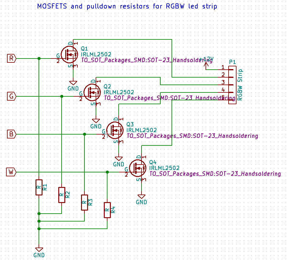
PS I just found this where I think they switched source and drain compared to my solution. This is mine:
I read that the leds have to be connected to the drain though...
-
For an N-channel MOSFET such as IRLML2502, source should go to GND and drain to 12V via the LED strip, as in your diagram (I'm assuming you're using common-cathode LED strips?).
Can you check the pinout of the MOSFET? The datasheet shows different pin numbers: IRLML2502
-
For an N-channel MOSFET such as IRLML2502, source should go to GND and drain to 12V via the LED strip, as in your diagram (I'm assuming you're using common-cathode LED strips?).
Can you check the pinout of the MOSFET? The datasheet shows different pin numbers: IRLML2502
@MikeF Thank you for your help! Yes they are commo-cathode, and yes it looks like the pins are wrong for the IRLML. I chose the standard SOT23 package in KiCad and it seems like I used the wrong pin number (wrong component in the schematics). Thats really annoying but at least I can now test it with the right pins.
-
By the way. What is the correct wiring?
The example on mysensors page shows no resistors. While the scematics on the internet state clearly that resistors are recommended.. Pic on the right...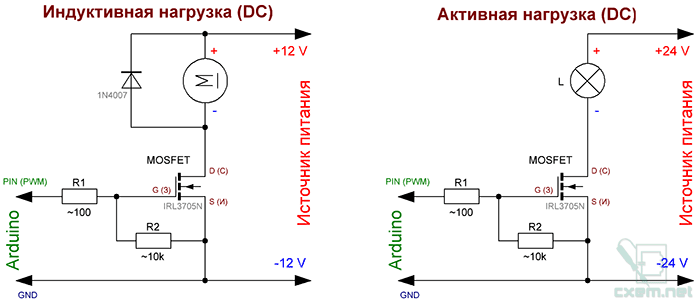
-
To protect a pin of the mcu driving the gate of a mosfet, it is good practice to put a 150 Ohm resistor between the pin and the gate.
As the pin can have floating output (on reset or startup), a pull down resistor is also added. That is what is shown in the diagrams on the internet. So they are in fact a better solution.
-
Thanks for your help guys. Got it up and running now :)
I used the pulldown resistors but did not use the current limiting resistors at the gates. Afaik you don't really have to but I will add them in my next version.@Admin I think it would be a great idea to update the build part for the leds to also use these resistors and perhaps add some text for RGB(W) leds as there is support for them now.
Hello! It looks like you're interested in this conversation, but you don't have an account yet.
Getting fed up of having to scroll through the same posts each visit? When you register for an account, you'll always come back to exactly where you were before, and choose to be notified of new replies (either via email, or push notification). You'll also be able to save bookmarks and upvote posts to show your appreciation to other community members.
With your input, this post could be even better 💗
Register Login