Very cool project :-)
Mister_ik
Posts
-
Old school phone as doorbell and domoitcs interface! -
💬 Easy/Newbie PCB for MySensors@sundberg84 ooh that is not very long ..i hoped for a couple of months....but then I should consider this board as depreciated and build a new one and use this for development. Thanks for your reaction.
-
💬 Easy/Newbie PCB for MySensors@sundberg84 yes i thought so, but i want to make sure. I have some Rev 10 boards and i was working on a node for my bathroom with a DHT11 sensor. I had some problems with it, therefore watching your video. But it looks like the step up booster was not working correctly. Unfortunately removing the booster i damaged the board because with a new booster the arduino won't get power any more. So this board only works without the booster (and reg jumper connected). Any idea how long this setup (with removed led on arduino) will last on batteries?
-
💬 Easy/Newbie PCB for MySensorsHello @sundberg84. I watched your video 9+ 'MySensors Battery Node 2xAA - EasyPCB (Nrf24l01+)and Temp Sensor' . I have two questions about this video:
- I noticed you connected the tempsensor to the extra prototype part of the board, but i could not see in the video how you connected signal pin of the sensor to the arduino.
- you added a resistor to D5 Temp/Hum, but you did not add the sensor to the mysX2.4 part of the board. Why is that?
-
Mysensors gateway (v2.2.0) keeps rebooting@mfalkvidd I never thought of that, but that could indeed be the case. In domoticz there is no data timeout configured. So still cant explain why domoticz is reconnecting.
@electrik i am not using MQTT with the gateway. I use still the 2.3.0 board.
-
Mysensors gateway (v2.2.0) keeps rebootingRecently I updated my MySensors gateway (ESP8266) to version 2.2.0. Perhaps i didn't noticed it while i used the older version, but because i updated it I noticed that the gateway is rebooting regularly. Still my sensors are working fine. I am using Domoticz as controler (latest beta)
2018-06-09 12:26:03.657 MySensors: Gateway Ready...
2018-06-09 12:26:03.657 Status: MySensors: Node: 0, Sketch Name: Gateway beneden
2018-06-09 12:26:03.658 Status: MySensors: Node: 0, Sketch Version: 1.0
2018-06-09 12:26:04.659 MySensors: Gateway Version: 2.2.0
2018-06-09 12:31:05.692 MySensors: Gateway Ready...
2018-06-09 12:31:05.692 Status: MySensors: Node: 0, Sketch Name: Gateway beneden
2018-06-09 12:31:05.693 Status: MySensors: Node: 0, Sketch Version: 1.0
2018-06-09 12:31:06.693 MySensors: Gateway Version: 2.2.0
Any ideas to narrow down this issue? I already tried several different radio's, but i don't have spare ESP8266 boards lying around
-
💬 Easy/Newbie PCB for MySensors@sundberg84 I just finished my first battery sensor node based on the Easy PCB Rev 9. I have two questions i hope you can help me with:
The first is about the battery measurement. Because i didn't have a 0.1 uf lying around i used an 0.2 uf capacitor. I am using the following script to measure the battery.
//=========================
// BATTERY VOLTAGE DIVIDER SETUP
// 1M, 470K divider across battery and using internal ADC ref of 1.1V
// Sense point is bypassed with 0.1 uF cap to reduce noise at that point
// ((1e6+470e3)/470e3)*1.1 = Vmax = 3.44 Volts
// 3.44/1023 = Volts per bit = 0.003363075
#define VBAT_PER_BITS 0.003363075
#define VMIN 1.9                                  //  Vmin (radio Min Volt)=1.9V (564v)
#define VMAX 3.0                                  //  Vmax = (2xAA bat)=3.0V (892v)
int batteryPcnt = 0;                              // Calc value for battery %
int batLoop = 0;                                  // Loop to help calc average
int batArray[3];                                  // Array to store value for average calc.
int BATTERY_SENSE_PIN = A0;                       // select the input pin for the battery sense point
//=========================


   // Calculate the battery in %
   float Vbat  = sensorValue * VBAT_PER_BITS;
   int batteryPcnt = static_cast<int>(((Vbat-VMIN)/(VMAX-VMIN))*100.);
   Serial.print("Battery percent: "); Serial.print(batteryPcnt); Serial.println(" %");
Do i need to change anything in the formula? Because i getting reading around the 130%
Requesting temperature...DONE
Temperatuur : 26.62 Degrees C
11935 TSF:MSG:SEND,25-25-0-0,s=5,c=1,t=0,pt=7,l=5,sg=0,ft=0,st=OK:26.6
Battery percent: 131 %
Battery Voltage: 3.35 V
Sleep...
12945 MCO:SLP:MS=900000,SMS=0,I1=0,M1=1,I2=254,M2=1
12955 TSF:TDI:TSL
If i use the following method:
//----
   // 1M, 470K divider across battery and using internal ADC ref of 1.1V
   // Sense point is bypassed with 0.1 uF cap to reduce noise at that point
   // ((1e6+470e3)/470e3)*1.1 = Vmax = 3.44 Volts
   // 3.44/1023 = Volts per bit = 0.003363075
   float batteryV  = sensorValue * 0.003363075;
   int batteryPcntNEW = sensorValue / 10;

   Serial.print("Battery percent: ");
   Serial.print(batteryPcntNEW);
   Serial.println(" %");
//----
I am getting: (this is expected, because batteries are new)
Battery percent: 99 %
Sleep...
12945 MCO:SLP:MS=900000,SMS=0,I1=0,M1=1,I2=254,M2=1
12955 TSF:TDI:TSL
My second question is about casing: any tips on which case to use which fit your board and a battery pack? and is as small as possible? Do you perhaps have links of your favourite (Chinese) sellers?
-
Problems with expanding my MySensors network@mfalkvidd Yes...it was indeed that simple. It works!! So thanks.
-
Problems with expanding my MySensors networkIs it so simple?
You only have to add : #define MY_RF24_CHANNEL 86 (before the MySensors.h) in both the sensor sketch as the gateway sketch?
-
Problems with expanding my MySensors networkI have a couple of sensor nodes in my house on the ground floor. Now i would like to expand the network in my house so i am trying to get my first sensors up an running on the first floor, but with no luck. It seems that the radio (NRF24) cant get trough my concrete floor (the floor is solid concrete and around 40 cm thick with a lot of iron for reinforcement). I don't have problems with walls, not even when signal has to travel to multiple rooms before reaching the gateway.
My first thought were "ooh lets build another ethernet/Esp8266 gateway and place this one on the first floor". But after i build this and trying to get this up and running i read that you can only have one gateway :-(
I already tried to extend the antenna of the radio, but with no luck. I don't have a power outlet near my stairs, for placing a repeater node. (and a long cable is not WAF proof)
So i was wondering anyone have a tip, for solving this problem. Thanks in advance!
-
Geeetech® Voice Recognition Module@ben999 said in Geeetech® Voice Recognition Module:
@dbemowsk Echo's family members only speak english and german so far...
That's my problem also...just English and German
-
Geeetech® Voice Recognition ModuleI was looking for new projects, so i was looking for new cool sensors and found the voice recognition module of Geeetech. Because of the price of the sensor, I was wondering anyone already played with this module and integrated it successfully in a home automation system? For me some basic commands would do for example Lamp on, lamp off, Dim lights. I know there are some nice products on the market as Google home, Amazon Echo but as long as you only can buy a US version i wont buy it.
I already found a page with setting up the sensor: http://www.instructables.com/id/How-to-use-a-Serial-Voice-Recognition-Module-Ardui/
So let me know your thought on this one.
-
PIR sensor and false positivesFinally i got some time this weekend to try out all of you tips. So thanks for those tips. Indeed the problem was solved when i moved the PIR away from the rest. But what i also noticed is that the PIR also have false positives (much less when it was near to radio, but still there where false positives) when it is close to the Arduino board and away from the radio. Therefore i decided to alter the setup and not to make the sensor a battery powered sensor, but use some ethernet cable to connect the sensors to the mainboard with the arduino and the radio. The cable is long enough to reach a wall outlet, so i can run the arduino and radio on normal power.
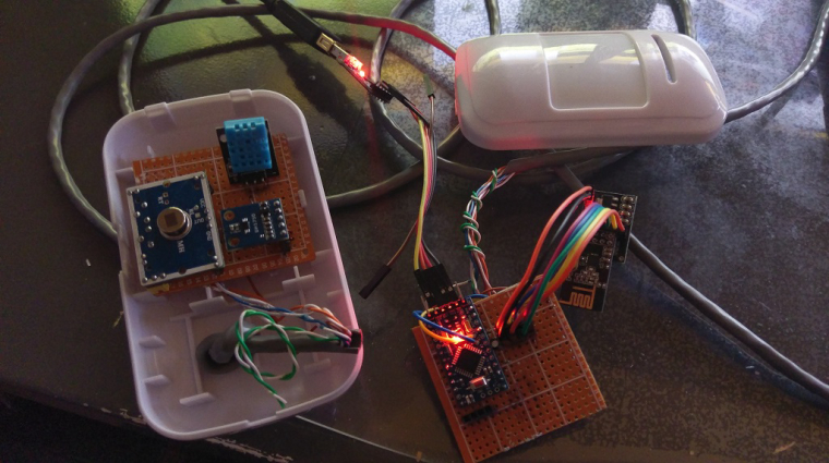
Because i had now all the space in the sensor module i added a DHT sensor. Now some new challenges arise. The sensor is working fine, but when the PIR is going off, it loops the sketch a lot of times (exactly 50 times) before it sleeps again. Perhaps someone can give me a hint which is causing this. My programming skills are not that good, so I have combined some different sample sketches. I am using currently the following sketch:/** * The MySensors Arduino library handles the wireless radio link and protocol * between your home built sensors/actuators and HA controller of choice. * The sensors forms a self healing radio network with optional repeaters. Each * repeater and gateway builds a routing tables in EEPROM which keeps track of the * network topology allowing messages to be routed to nodes. * * Created by Henrik Ekblad <henrik.ekblad@mysensors.org> * Copyright (C) 2013-2015 Sensnology AB * Full contributor list: https://github.com/mysensors/Arduino/graphs/contributors * * Documentation: http://www.mysensors.org * Support Forum: http://forum.mysensors.org * * This program is free software; you can redistribute it and/or * modify it under the terms of the GNU General Public License * version 2 as published by the Free Software Foundation. * ******************************* * * REVISION HISTORY * Version 1.0 - Henrik Ekblad * * DESCRIPTION * Motion Sensor example using HC-SR501 * http://www.mysensors.org/build/motion * */ // Enable debug prints #define MY_DEBUG // Enable and select radio type attached #define MY_RADIO_NRF24 #define MY_NODE_ID 130 #include <SPI.h> #include <MySensors.h> #include <BH1750.h> #include <wire.h> #include <DHT.h> #define CHILD_ID_MOTION 131 // Id of the motion sensor child #define CHILD_ID_LIGHT 133 // Id of the Light sensor child #define CHILD_ID_HUM 134 // Id of Hum sensor child #define CHILD_ID_TEMP 135 // Id of temp sensor child #define DIGITAL_INPUT_SENSOR 2 // The digital input you attached your motion sensor. (Only 2 and 3 generates interrupt!) #define INTERRUPT DIGITAL_INPUT_SENSOR-2 // Usually the interrupt = pin -2 (on uno/nano anyway) #define DHT_DATA_PIN 4 // The digital input you attached your DHT sensor. #define SENSOR_TEMP_OFFSET 0 // Set this offset if the sensor has a permanent small offset to the real temperatures // Sleep time between sensor updates (in milliseconds). Must be >1000ms for DHT22 and >2000ms for DHT11 static const uint64_t UPDATE_INTERVAL = 300000; //unsigned long SLEEP_TIME = 300000; // Sleep time between reports (in milliseconds) // Force sending an update of the temperature after n sensor reads, so a controller showing the // timestamp of the last update doesn't show something like 3 hours in the unlikely case, that // the value didn't change since; // i.e. the sensor would force sending an update every UPDATE_INTERVAL*FORCE_UPDATE_N_READS [ms] static const uint8_t FORCE_UPDATE_N_READS = 10; float lastTemp; float lastHum; float lasttripped; uint16_t lastlux; uint8_t nNoUpdatesTemp; uint8_t nNoUpdatesHum; uint16_t teller; bool metric = true; BH1750 lightSensor; DHT dht; // Initialize motion message MyMessage msgmotion(CHILD_ID_MOTION, V_TRIPPED); MyMessage msglux(CHILD_ID_LIGHT, V_LEVEL); MyMessage msgHum(CHILD_ID_HUM, V_HUM); MyMessage msgTemp(CHILD_ID_TEMP, V_TEMP); // -------------------------------------------------------------------------// // setup // -------------------------------------------------------------------------// void setup() { // setup of Lux sensor lightSensor.begin(); pinMode(DIGITAL_INPUT_SENSOR, INPUT); // sets the motion sensor digital pin as input // setup of DHT sensor dht.setup(DHT_DATA_PIN); // set data pin of DHT sensor if (UPDATE_INTERVAL <= dht.getMinimumSamplingPeriod()) { Serial.println("Warning: UPDATE_INTERVAL is smaller than supported by the sensor!"); } // Sleep for the time of the minimum sampling period to give the sensor time to power up // (otherwise, timeout errors might occure for the first reading) sleep(dht.getMinimumSamplingPeriod()); } // -------------------------------------------------------------------------// // presentation // -------------------------------------------------------------------------// void presentation() { // Send the sketch version information to the gateway and Controller sendSketchInfo("Motion + Lux + DHT", "1.0"); // Register all sensors to gw (they will be created as child devices) present(CHILD_ID_LIGHT, S_LIGHT_LEVEL); present(CHILD_ID_MOTION, S_MOTION); present(CHILD_ID_HUM, S_HUM); present(CHILD_ID_TEMP, S_TEMP); // Bepalen nodeID uint8_t getNodeId(); Serial.println(); Serial.print("NodeID : "); Serial.println(getNodeId()); Serial.println(); teller = 0; metric = getControllerConfig().isMetric; } // -------------------------------------------------------------------------// // loop // -------------------------------------------------------------------------// void loop() { //---------------------------------- // **** BH1750 Lux sensor //---------------------------------- Serial.println("------------------------------"); Serial.println("Requesting Light level..."); uint16_t lux = lightSensor.readLightLevel();// Get Lux value Serial.print("lux : "); Serial.println(lux); if (lux != lastlux) { send(msglux.set(lux)); lastlux = lux; } else { Serial.println("lux is nog hetzelfde : "); } //---------------------------------- // Read digital motion value //---------------------------------- Serial.println("------------------------------"); Serial.println("Requesting motion..."); bool tripped = digitalRead(DIGITAL_INPUT_SENSOR) == HIGH; Serial.print("Beweging sensor : "); Serial.println(tripped); if (tripped != lasttripped) { send(msgmotion.set(tripped?"1":"0")); // Send tripped value to gw lasttripped = tripped; } else { Serial.println("Motion is nog hetzelfde : "); } // Force reading sensor, so it works also after sleep() dht.readSensor(true); //delay(dht.getMinimumSamplingPeriod()); //---------------------------------- // Get temperature from DHT library //---------------------------------- Serial.println("------------------------------"); Serial.print("Requesting Temperature..."); float temperature = dht.getTemperature(); Serial.println("DONE"); if (isnan(temperature)) { Serial.println("Failed reading temperature from DHT!"); } else if (temperature != lastTemp) { #ifdef MY_DEBUG Serial.print("OLD Temperature : "); Serial.println(lastTemp); Serial.print("NEW Temperature : "); Serial.println(temperature); #endif // Only send temperature if it changed since the last measurement or if we didn't send an update for n times lastTemp = temperature; if (!metric) { temperature = dht.toFahrenheit(temperature); } send(msgTemp.set(temperature, 1)); } //---------------------------------- // Get humidity from DHT library //---------------------------------- Serial.println(); Serial.print("Requesting Humidity..."); float humidity = dht.getHumidity(); Serial.println("DONE"); if (isnan(humidity)) { Serial.println("Failed reading humidity from DHT"); } else if (humidity != lastHum ) { #ifdef MY_DEBUG Serial.print("OLD Humidity : "); Serial.println(lastHum); Serial.print("NEW Humidity : "); Serial.println(humidity); #endif // Only send humidity if it changed since the last measurement or if we didn't send an update for n times lastHum = humidity; send(msgHum.set(humidity, 0)); } //---------------------------------- // Sleep //---------------------------------- teller++; Serial.println("------------------------------"); // Sleep for a while to save energys Serial.print("teller...: "); Serial.println(teller) ; sleep(INTERRUPT, CHANGE, UPDATE_INTERVAL); Serial.println(); } // -------------------------------------------------------------------------// // END : einde script // -------------------------------------------------------------------------// -
PIR sensor and false positives@NeverDie @mfalkvidd I am also curious how you have done that. I picture would be nice!
-
PIR sensor and false positivesAfter building my first combined sensor (not battery powered) i got enthusiastic about the MySensors project. This project as you can see was based on Arduino Nano and is working like a charm
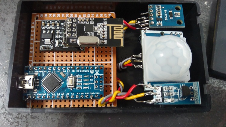
So i wanted to add more off these combined sensor nodes to my smart house. This time i wanted to try a battery powered sensor based on Pro Mini (5v version) and built the following sensor:
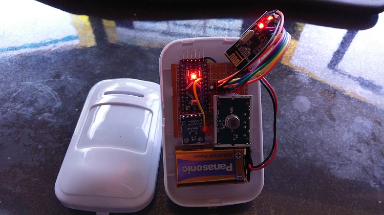
Both project use the same PIR & BH1750 sensor and are running the same sketch (the second without the temperature sensor), but the second project (even if project is not powered by the battery) gives a lot of (and i mean a lot of) false positives.
I already checked the following things:
-
tested the PIR also on breadboard with a Nano and there it is working fine
-
the project with only the lux sensor is working fine (only removed the PIR in the sketch)
Can anyone confirm if i can rule out the difference between the boards i used (Nano and Pro mini)? Or perhaps does anyone can point me in the right direction how i can solve this?
-
-
How To - Doorbell Automation Hack@petewill Thanks for pointing me in the right direction. I am not a programmer but i managed to get this working with your sketch and the example sketch of the relay
-
How To - Doorbell Automation HackThanks for this great project/hack.
I built this project and it is working great, but i have a question about this. My controller is Domoticz and in Domoticz i have the two switches (DOORBELL_CHILD_ID, SWITCH_CHILD_ID). I though with this project i could also use the ringer of my doorbell as a sort of alarm in other combinations, but if a use the doorbell-switch in Domoticz the doorbell won't ring. But if i use the normal doorbell at my front door, it will ring.
Is there something wrong in my sketch or am i missing something else?
Thanks in advance for your help!
-
Mysensor gateway node is not connecting to Domoticz@mfalkvidd Thank you.....if forgot to upload the gateway software. I thought flashing the NodeMCU was enough. And of-coarse i had to update in the gateway software also the router information. That was the step i forgot :-(
-
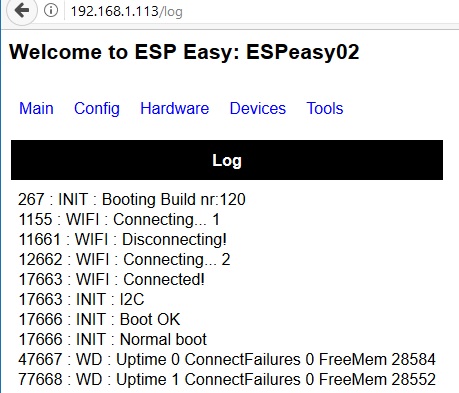
Mysensor gateway node is not connecting to DomoticzThis is what the log says: (i rebooted to show you a clear log, otherwise only the uptime messages are shown)
-
Mysensor gateway node is not connecting to DomoticzI changed to new router from my internet provider (Ziggo). After adding all my fixed IP-adresses i have problems with mySensors gateway. It will not connect to Domoticz. I am now lost i tried a lot of things...but i don't understand why it is not connecting.
My setup is:
- Domoticz v3.8394 on RPI
- Mysensor node : ESP Easy NodeMCU (uploaded with https://www.letscontrolit.com/wiki/index.php/Tutorial_ESPEasy_Firmware_Upload)
My log is saying:
2017-09-15 23:21:27.287 New sensors allowed for 5 minutes...
2017-09-15 23:21:28.954 TCP: Reconnecting...
2017-09-15 23:21:29.955 Error: MySensors: Can not connect to: 192.168.1.113:5003
2017-09-15 23:21:29.955 TCP: Connection problem (Unable to connect to specified IP/Port)
2017-09-15 23:21:29.955 TCP: Reconnecting in 30 seconds...
From pi RPI i can ping the mysensor IP
pi@raspberrypi:~$ ping 192.168.1.113
PING 192.168.1.113 (192.168.1.113) 56(84) bytes of data.
64 bytes from 192.168.1.113: icmp_seq=1 ttl=128 time=9.43 ms
64 bytes from 192.168.1.113: icmp_seq=2 ttl=128 time=9.56 ms
64 bytes from 192.168.1.113: icmp_seq=3 ttl=128 time=10.0 ms
64 bytes from 192.168.1.113: icmp_seq=4 ttl=128 time=10.6 ms
I can connect with browser to mysensor node:
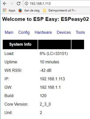
The following things i checked:
-
all components are on the same IP-range
-
in the settings page i set the 'local notwork'
-
I built a new node but this new node gives the same problem.
-
ect.
Anyone have a clue? Thanks in advance.
