Good idea, I'm on.
Living in Lund so Malmö is excellent.
Posts made by olaeke
-
RE: Meet in Malmö, Summer 2016?
-
RE: [contest] My Gateway
@Newzwaver All hardware except 433MHz antenna is from MySensors "Store". I found the antenna on ebay and the box for everything is bought here in Sweden (http://www.kjell.com/se/sortiment/el/elektronik/elektroniklador/ventilerad-inbyggnadslada-95x135-mm-p89012)
-
RE: [contest] My Gateway
@msebbe Now I didn't see your replay
About your edit2. I also had som problem in the begining due to weak power supply. I now use a >2A wall plug and that works great. -
RE: [contest] My Gateway
@msebbe I connected the antenna with the 433 sender with a short coax cable. If it is short distance I think you can use just a simple cable. Or maybe this was not what you where asking for...
-
RE: UI 7 Ethernet Gateway Problem
@jeylites Ethernet or serial gateway?
You can try this http://forum.mysensors.org/topic/838/windows-gui-controller-for-mysensors program it is excellent for troubleshooting, with this you can verify that your gateway and sensors work correct. -
RE: Newbie
I have a Vera Edge and that is running fine.
You need the latest Vera files from Github for updated UI. -
RE: Decoupler capacitor
You can say that for decoupling of the power supply it is better the bigger you have (within some reason) So 47µF is better than 4.7µF, I use 10µF on all my radios and that is Ok I think 4.7µF is a bit to small.
-
RE: Scene too fast for gateway?
@Zeph I dont't think it has to do with the powersupply. I have the same problem and I power my Gateway with 2A supply and on the radio I have 47uF. I have a coulple of scenes that turn on/off lamps and in my case it looks like there is a limit around 4 devices, if the scene contains more than 4 devices whith no delay then it often miss some of them. But when I added 1 sec delay between every third device then it works fine.
-
RE: Scene too fast for gateway?
@ferpando I have actually exact the same problem right now but I expect that the Vera Edge is the problem. I looks like some devices are present in the scene but they are still not present. I have created a scene with about 10 devices in and that looks ok in the scene but when I look on the "scene info" on each device then some of them doesn't says that i exist in that scene. I have also made a quick check on the serial debug and it looks like the Vera doesn't send command for all devices. Right now I'm recreatcing my scene to verify that all devices actually are included.
I'll be back....
-
RE: Dummy Camera - Temp/Hum/Motion housing
Smart idea! I will se if I can find similar.
-
RE: [contest] My Gateway
@Dan-S. Yes that is also my theory but my powersupply is on 2A so quit powerfull. I haven't calculated on the total power need, maybe I should do that...
-
RE: [contest] My Gateway
@axillent No actually I have a separat sensor node (MCU + NRF24) for the 433MHz. I did some experiments with combining my actuator in the gateway but I was never succeded to get proper and stable function so I gave it up.
I allways get envious on your builds, it is really a good work!
-
RE: [contest] My Gateway
@epierre Any brand, because I "listen" with my "poor man oscilloscope" to the existing datastream and then I hardcode this protocol in My433Node.h
-
[contest] My Gateway
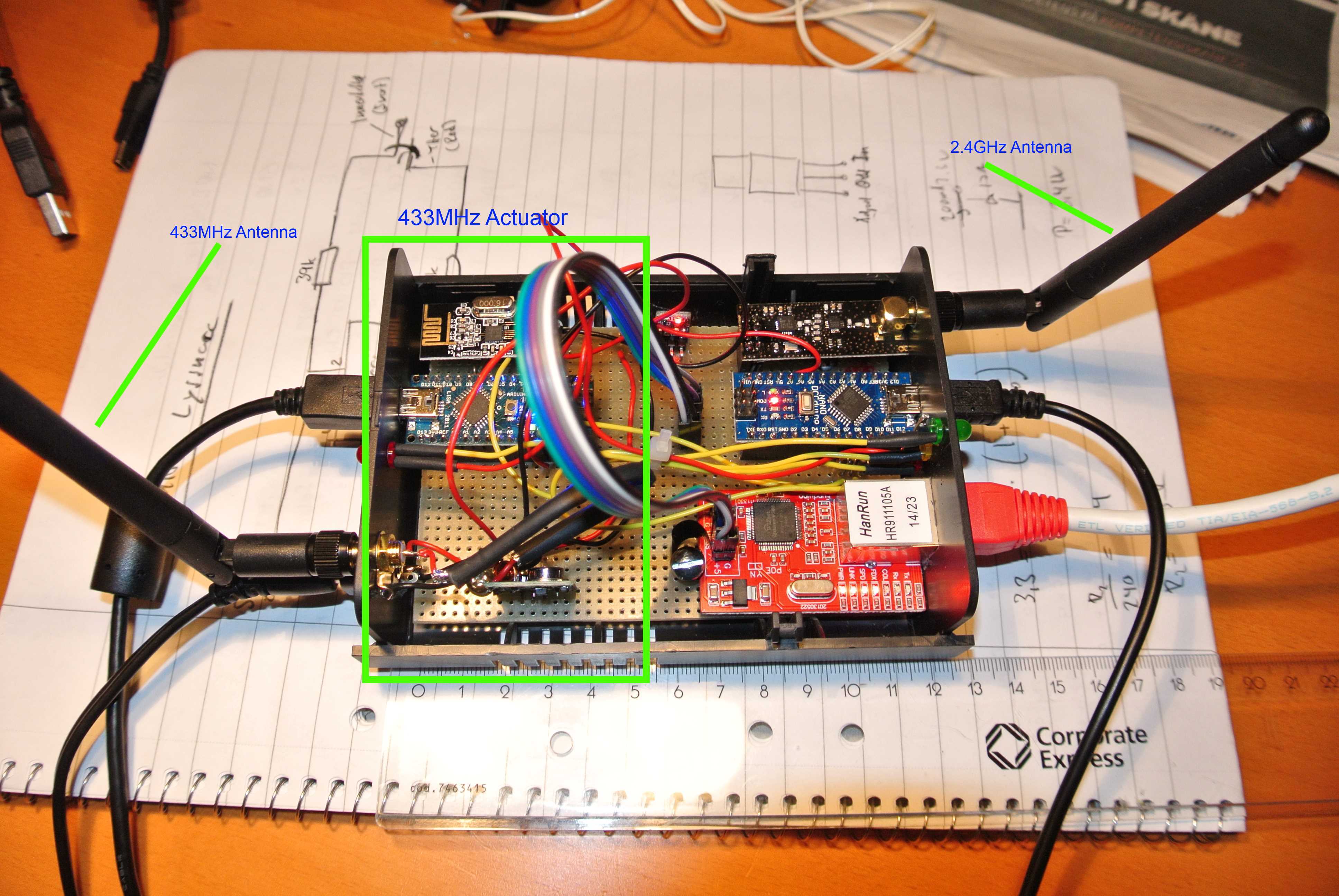
Historically my wife has filled our house with different brands of 433MHz switches. When I bought my Vera two months ago I realized that it will be too expensive to replace all those old switches with new nice Z-wave switches so then I started with MySensors stuff to create a actuator for controlling all this old stuff.
Since it is a lot of different brands (no Nexa stuff) I couldn't get them to work with those samples library that you can find around. Instead I have to build my RF listener and try to decode the signal. I can't find the link right now to the listener but you connect a 433MHz receiver to the mic input on your computer and then use the Audacity program to record the signal.
Then I created a lib and a sketch for my different switches and it worked on my breadboard. So finally I packed everything, a gateway and my 433MHz actuator, in a box.
It works fine, and the WAF is for the moment on top.
One problem is that that the gateway and Ethernet module sometimes just stops and need a restart, I will investigate this further on when I got some time.
Some pictures:
My generic 433MHz lib
My433Node.h
And a sample sketch
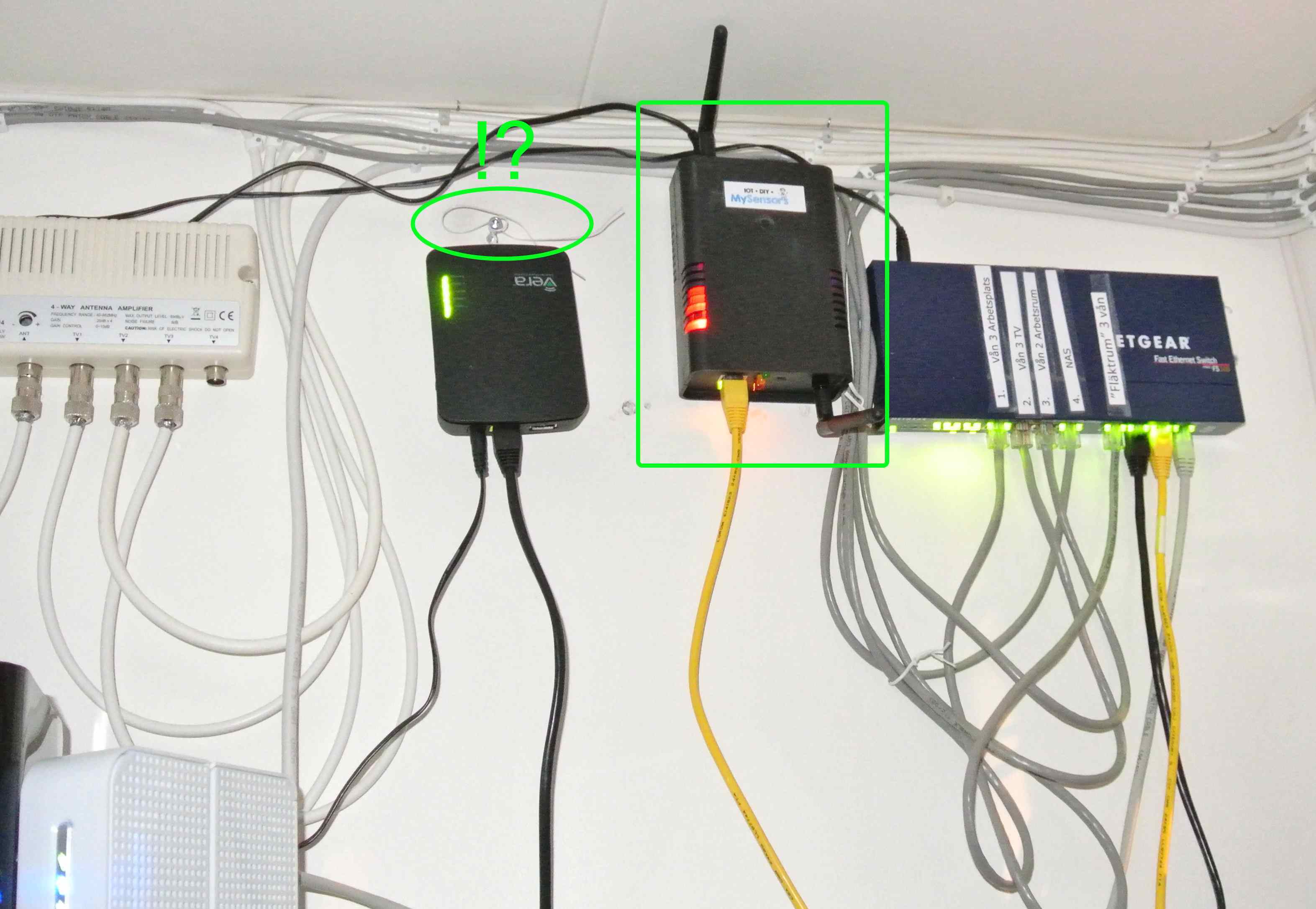
My433Node.inoNow it is mounted in the "engine" room, "branded" and all. On the left is the Vera, notice that I had to mount the Vera with a string because Micasa Verde has "forgot" to make wallmounting holes in the box!! (that is not the only thing they forgot on the Vera Edge..)
-
RE: UI7
@Dany You will get 1.41 on the download link http://www.mysensors.org/download/. I have no problem access my Gateway with Ethernet, I'm using W5100 module and the lib from the download link.
-
RE: UI7
@Dany Can you ping your gateway? Sometimes I have problem that my Ethernet just "die", but after reset on card and Arduino it works again.
-
RE: Soil Tensiometer Sensor Network
@aur I don't think Vera is the ultimate controller for your project, I would have take a look an all open source controllers listed on the Controller page
-
Gateway - Ethernet stops
I got a problem that the Ethernet card sometimes (actually very often) just turns "off", all the leds stops blinking so it looks like dead. If I unlug the networkcable and plug it in again then all leds start to blink again. However I can't ping the IP adress until I have done reset on the Arduino.
I use one 5v 2A powersupply for 2 Arduino, 2 Radio, 1 Ethernet module and one 433MHz transmitter. Could it be to little with 2A for this? Have
Anyone else experienced the same or similar problem? -
RE: Small wall outlet sensor node
@axillent Very nice! How do you make the circuit board and the soldering of surface mounted components is quit advanced.
-
RE: Approved in-wall switches and dimmers
@Session You are right about the downside of one-way communication. I use cheap 433Mhz on lamps that is not "critical" and then z-wave devices on more critical things, the z-wave is to expensive. I agree I wouldn't put homemade 230V things inside my walls.
-
RE: Approved in-wall switches and dimmers
@Session Buy 433MHz switches, you can find both as plugs and as wall in. Then build a MySensors actuator to Control them using the "Wireless Transmitter and Receiver Link Kit Module 433Mhz" on the http://www.mysensors.org/store/ page. You can find sample code in the sample folder (\MySensors\Arduino-master\libraries\NewRemoteSwitch) to Control many 433MHz devices or you can sniff the 433MHz signal and build your own sketch (as I did)
-
RE: Vera Arduino Plugin
- If you are running UI7 then I recommend that you download newer files from GitHub ([https://github.com/mysensors/Vera/tree/UI7](link url) )
- Install **all **files (mentioned in the instruction not all files from GitHub) to Vera under Apps/Develop apps/Luup files (in UI7)
- Create the device as the instruction says
- Connect your Gateway
- Now hopefully your gateway will turn up as a device and with the text "Connected to: 192.........."
-
RE: Leapmotion
And Mi Casa Verde has problem to get the USB port to work on Vera Edge
-
RE: Radio setup give: "check wires"
@slarti HaHa so in China they sell NRF24L01+. and you get NRF24L01 but in Finland they sell NRF24L01 and you get NRF24L01+.
-
RE: Radio setup give: "check wires"
@slarti You can test to set a static id on the sensor in the gw.begin like;
gw.begin(NULL, 25);
this sample set id fixed to 25 on this node. At least that was one of my problem with this radios, but my advice is to by new radios the cost is so smal compared to the effort. However it is the shiping that is the problem.
-
RE: Car present detector needed
I you plan to put a sensor in your car you should add proper protection on the power supply to protect against load dump. You can get peak voltage up to 100V for several of ms, that kill most unprotected Electronic.
-
RE: UI7
@hek Done, I have not used GitHub before (more used to MS Tools) and there was some steps to take to check in but I hope I managed to do it.
-
RE: RelayWithButtonActuator - another n00b question
@gadu You should be aware that the delay function stop the processing so it is a huge chance that you will miss incoming messages because 99% om the time the mainloop will hang waiting. Try use millis() function instead
-
RE: Radio setup give: "check wires"
@axillent Yes there is no + on those.
I have tried using them but without success. I couldn't get them to work at all on the gateway but if I replaced the gateway with + variant and non + on the node then it "almost" worked. I couldn't get the "Auto Id" function to work. I think it has something with Ack to do, i will remember that I have read somewhere that the hardware ack is only implemented in the + variant. -
RE: nRF24L01 + and 433MHz RF on the same Gateware
@jesper Sounds like a callenge! Everything is of course possible but i.e there is no hardware Ack on that 433MHz radio so except replace the radio there is also "some" logic in the radiolib to deal with. That radio receiver is also quit noicy so you need a good radio protocol and probably also some software filter.
-
RE: Radio setup give: "check wires"
@axillent And me! I started the thread so I have got 10 of the them, maybe something for the MySensors museum!
-
RE: UI7
@axillent Sure what do I need to place it in the source control? I have an account on GitHub
-
RE: UI7
I have now modified the json files (and some more) to make the UI better match the UI7. I have moved most of the information to the Settings tab to keep the dashboard clean and hopefully keep the space down. Now it turns out that the "brick" on the dashboard still is ridiculous big (70% whitspace) but i hope this is a bug in UI7 that "Vera Control" will fix (soon...).
Anyone interested to get the modified files ?
When I'm "online" i must complain on "Vera Control", what was they thinking on when designed this
new dashboard? I'm new to Vera so I have only 10 devices so far but I plan for 30-50 devices then
I think the dashboard (or even the total UI) will be totally useless, it is to much whitespace
which makes to much scrolling in the UI.Here is an example of the result:
-
RE: UI7
@axillent No so far it is only "look and feel", but I have only tested my Relay node
-
RE: UI7
@gregl Yes I have seen the dump on http://www.mysensors.org/controller/vera but how does the setting page looke like in UI5 ?
-
RE: Ethernet GW how know?
@ch3b7 Are you sure you have enabled SOFTSPI by uncomment #define SOFTSPI in RF24_config.h? It is easy to make the change in the wrong library file and not in the one that is acctually used by the IDE
-
UI7
Finally I have got my relay sensor to work with my Vera Edge (UI7) with Ehternet Gateway. The serial doesn't work because the serial port is not working on any Edge, quit amazing they can release a new hardware and "forget" to test the USB device.
Anyway the device looks a "bit" (understatement) different in UI7 compared to UI5. I'm trying to change the Json code för UI7 so my question is if anyone can provide me with screendumps on MySensors in UI5.
-
RE: No debug data from sensors or gateway. Bad radios?
@slarti Yea I know the feeling, I had planed for Home Automation stuff in the Christmas holiday then I got this shit from China a non working Vera so it was quite frustrating
-
RE: How does Vera display complex nodes
@daulagari In UI7 (Vera Edge) you get one device for the node and one device for each Child, named Adruion7:3, Adruion7:11... But then ofcourse you can cange name of them in Vera.
There is some minor cosmetic stuff with the presentation of the node in UI7.
-
RE: No debug data from sensors or gateway. Bad radios?
@slarti I think that the difference is that the ping pong test doesn't use acknowledge and my experience from NRF24L01 (no plus) chip it that it is the ack thing that differ and that cause the problem.
My recomendation: by new radios from the link on MySensors Store page.
-
RE: Radio setup give: "check wires"
@Squint That seem even more tricky that the have printed + on the chip and then it still is non plus.
I really don't remember now if I run the getstatus() on the sensor node or it was only on the gateway, but it sound strange that you get zeros on all information. The only thing I can think of is either is the radio broken or is there som more #define in the code you have to comment out the get the status info to print correctly.
I will also remember that I had to fix some more issue in the code to get the non plus to work, I think a made a hack in the process method in the MySensor class, and still the acknowledge didn't work. But I'm not totally shure, I have had a lot of problem with my sensors and my Vera Edge.
Yesterday I received my new radios (yes + variant) and my Ethernet shield. I have now replaced my radios, replaced the serial gateway with Ethernet (the serial port is not working on Vera Egde, good work Mi Casa Verde!) replaced all my hacked library code with fresh from MySensors.org and...
NOW IT WORKS!
I will take the old non plus radio and burn them in the garden tomorrow!
FYI as sonicblaze wrote is Alice breaking point to give them bad feedback then they contact you within a week and offer you refund,.
-
RE: Radio setup give: "check wires"
@Squint I have problem with Ack and I have assumed that it has to do with the non + . I have a + variant on my gateway but non puls on my sensor node.
-
RE: Sensor on gateway
You have to rewrite part of MyGateWay.cpp or create your own class. It is not that easy that it looks like at first glance. I did it but it didn't end up in that good functionality so I skipped it and made a separte sensor and keept the Gateway unchanged.
You have another answer in the same direction here: http://forum.mysensors.org/topic/722/is-it-possible-to-have-an-ethernet-gateway-also-act-as-a-node-single-arduino-setup/4
-
RE: Current Monitoring - How?
@Dean I don't know about this module but are you thinking of connect this one to the live 220V/110V/..V ? On the picture it looks like it have to small isolation distance for that.
-
RE: Vera Edge
@C.r.a.z.y. Did you manage to get some Contact between the gateway and Vera?
I only get the message "Lua Startup Failure Can't Detect Device" on the MySensors Plugin device and on top of the screen I get this two messages:
MySensors plugin : Choose the Serial Port
MySensors Plugin[5] : Running Lua Startup -
RE: Less Optimised Code for Beginners PLEASE?
@bluman
If it is the ? operator that is the fuzzy one then you can rewrite the statement like:if (message.getBool()) digitalWrite(message.sensor-1+RELAY_1, true); else digitalWrite(message.sensor-1+RELAY_1, false);
The ? operator act like: expression?truepart:falsepart
So if expression is true the it executes the truepart else it executes the falsepart -
RE: Serial terminal
@ch3b7 But this (excellent) program is the replacement for the controller (for test purpose). You will write a program that send data to the controller, so you will replace the gateway or what are you trying to achieve?
-
RE: Radio setup give: "check wires"
I can confirm that you can get non + variant to work on nodes but on the gateway you must have a + variant.
But it is not worth the effort, if you have got non + variant from the China, throw them away and by new one (and cross your fingers that you get correct next time)
-
RE: Radio setup give: "check wires"
@boozz and @sonicblaze
Did any one of you get the non + variant to work?
It does work with the PingPong test program (posted above) but as Gateway and/or Sensor I can't get them to work. -
RE: Radio setup give: "check wires"
I have modified the excelent "ping/pong test" program from maniacbug so it compiles with the RF24 lib. that comes with MySensors 1.4
With this program it is very easy to test your radio if it works or maybe if it works bad (many timeouts) and you also get this info printed if it is a + or non + chip.
- Download attached zip
- Build ino file
- Uppload on two nodes
- Connect serial monitor (115200 baud)
- Press T in serial monitor and then you should se "
Now sending 29788...ok...Got response 29788, round-trip delay: 23"
For the printout of chip details you need to comment out #define MINIMAL in RF24_config.h. I also recommend comment SERIAL_DEBUG so you get less debuginfo on serial.
MySensorsPingPongTst.zip -
RE: Radio setup give: "check wires"
@hek
Yes I have an ebay account, I can login with this and se all my prev. orders. If I click on this radio order I come to the detail page and I select "Contact Seller" and then I come to a page with 5 topic, but whatever i select I end up on that "...Contact PayPal..." page -
RE: Radio setup give: "check wires"
@sonicblaze and @hek:
I finally had some time to test this and yes my chip is also a "non +", the RF24::printDetails(); gives:
Model = nRF24L01I managaged to get RF24::printDetails(); to work in MySensor::begin after setupRadio(). There are some steps to take:
- In RF24_config.h you have to comment out #define MINIMAL (ln 27)
- Then in your sketch you have to define stdout like
include "printf.h"
void setup()
{
printf_begin();
I can't contact the seller, when I click "contact seller" (or return or whatever) in ebay I only get to this page:
"You purchased this item as a PayPal guest user and will need to contact PayPal directly by going through their Resolution Center."
I don't understand because I payed my order with MC as usual.
printf.h -
RE: Radio setup give: "check wires"
Just tried to find a way to concat "alice.." on ebay but whatever link I click on I end up on "You have to Contact seller trought paypal.."
Shit so then it ends up in a new order and another 3 weeks wait for new delivery! And I also don't get my Vera as I have order 5 weeks ago so it turns out to be kind of failure with my homeautomation christmas holiday.
No luck with Santa this year
-
RE: Radio setup give: "check wires"
@sonicblaze: Yes my radio as also without the + sign, but my antenna version is with the + sign, however I haven't have time to test this yet. I order them both at the same time from alice..... and I will also contact them now.
Is it the same pinout on the antenna version since there is not printing on that board?
-
RE: Radio setup give: "check wires"
Yes I bought my radios from MySensors link and I ordered them sometimes at the end of November. I will look at my chip tonight and come back.
-
RE: Radio setup give: "check wires"
@hek: The cap. is a electrolyt on 4.7uF so it should be Ok but i will try to remove it or decrease it to 1uF.
@tbowmo: Is far as I can se on all spec. pages it looks like the pinout for SCK (13), MOSI (11) and MISO (12) is the same on Mini and Nano. Chip enabled and Chip select is not so critical since it is configurable in MyConfig_h but I use the default 9 and 10 for this. For The IRQ line I use #2 (INT0). IRQ line is same in Mini and Nano.
-
RE: Radio setup give: "check wires"
Here is radio wiring
I don't think another sketch will help since i stop on:gw.begin(incomingMessage, AUTO, true);
And this calls setupRadio which look like this:
.....RF24::begin(); if (!RF24::isPVariant()) { debug(PSTR("check wires\n")); while(1); }
...
So it stops because it is not pVariant. BUT since I have bought the radio on MySenors link and it says on ebay that it is a NRF24L01+ i will strongly belive that it is a + variant. -
Radio setup give: "check wires"
I'm pretty tired on this now, I have spent 2 nights and half this day on this problem. I think I have read all threads on this forum and tested every tip but still only get "check wires" when i fire upp my sensor. I have no "reference" working copy of a sensor so I can't verify that my Nano and radio is ok but since I have tested 2 nano and 3 radios it should be ok.
Is there any other way to test the hardware? Or is there any tip how to proceed? If there is any mySensor user in Sweden then I can send a radio to you and you can verify that it is ok?
I'm out of ideas now.
I cant get my sensor to work. After reset I only get the message "check wires" on the serial monitor. And yes I have checked the radio Connection many times, I have attached an image with my wireing maybe someone with "new fresh" eyes can see anything. I have also connected decoupling capacitor.
- I'm runing Nano
- Latest download of MySensors library
- Radio modul bought from the link on MySensors shop.
- I run the radio from external 3.3 V (so red cabel on picture is not there anymore)
- I run the RelayActuator sketch from the samples without any modifications
- I have only one sensor, no gateway
- I have tested two different Nano and two different radio
-
RE: Is it possible to have an Ethernet Gateway also act as a node(Single Arduino setup)?
I you success so let us know, I think that we are some out here that are interested in this.
-
RE: Vera Edge
Great Hek I go for that one.
It seams that both Vera 3 and Light is hard to get here in Sweden now. -
Vera Edge
Hi
Do anyone has any information/progress on MySensors togheter with Vera Edge.I was finnaly ready to begin my homeautomation Project with Vera and MysSenors but when try to order Vera Lite my supplier says that it is not manufactured anymore and offer me a Edge instead.
-
RE: Combine Gateway and Sensor
Thanks but that thread ended on the difficult part:
"please, help to send the presentation string when inclusion mode has been triggered"
Anyone have a idea about this?It would be easier to include one more Arduino and a radio but the hardware and programming is one of the fun part with MySensors
Regards
-
Combine Gateway and Sensor
I just started do some playing around with MySensors and it looks great (still waiting for my Vera to arrive)
But my first question if it is possible to combine a Sensor in a GateWay. Where I will install my Gateway I also want to control 2 relays.I can see that there maybe will be a conflict in gw.begin(..), and the gateway should act on message that come from Vera and are adressed for the relay.