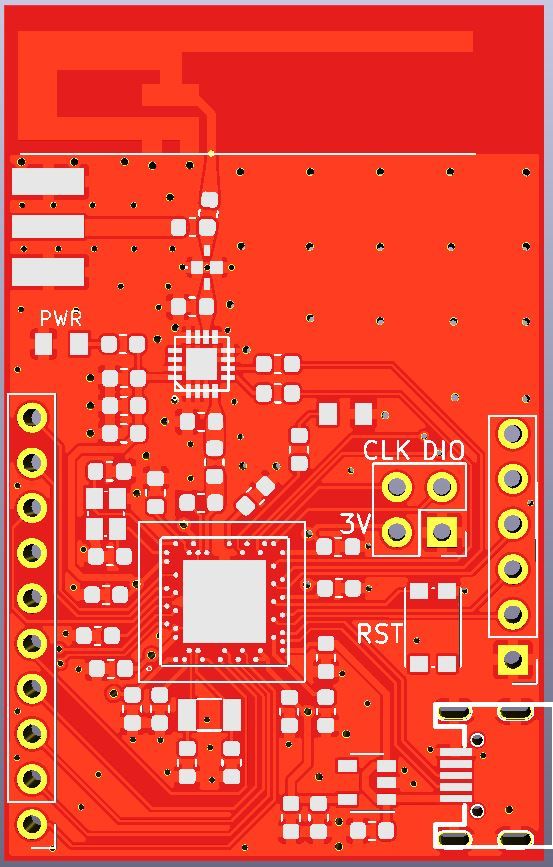
I just gave this design to pcb fab and cant wait to test it out. I made and tested a similar board using nrf52840 but soldering aQFN package is a nightmare and i needed to cancel quite abit of pins to increase the success chance.
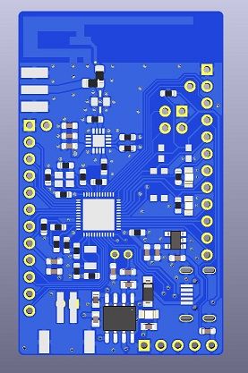
So this design is based on nrf52832with a normal QFN package which is easy to solder and that allowed me to breakout every single pin (except P0.07). Can be powered with a single cell lipo or USB port and managed to fit in a charger for it with a charging indicator led. It has a voltage divider to measure the battery but it can be desoldered if the pin is needed for another function.
Comes with PA and LNA just like my nrf52840 test and had to follow quite abit of design recommendations from the datasheet.
Some pins are compatible with adafruit 52832 circuit design just in case if i want to use their bootloader. Like reset, DFU, 2 different leds are connected to the same pins as in their board design. Also theres a selector 0 ohm resistor between pcb and external antenna.
I will report when i receive and test it!
orhanyor
Posts
-
nRF5 action! -
Anyone cleaning the flux off using an ultrasonic cleaner?@NeverDie the ethanol i bought from the pharmacy was very cheap 150ml bottle on the label it says it is for disinfection the skin like before penetration of needle etc its for medical use but what matters is its %90 the rest is clean water it says on the label.
theres absolutely no oily or stick residue otherwise i wouldnt have used it. I did like 10 boards 2-3 with IPA, ethanol, acetone and water based solution while testing.
I watched quite abit of videos in youtube most of the people dunk the pcb in clean deionised water as a final wash to eliminate any left residue. Unfortunately i dont have it but i will buy some soon and i will do the same but for now no residue at all.
wow! denatured alcohol is so cheap over there. i would have definitely tried it :) i mean if it works it works.. just need to test it with some scrap pcb but on the other hand you are right about the handling it. it might be toxic especially if theres methyl alcohol in it but the one i got supposed to be used on human skin so i believe its completely safe. Safest bet is probably IPA and with the plastic bag method you really minimize the evaporation and amount used so it should last for quite some time. its just good practice to put it back into its bottle(different one ofc). today i noticed a small leak in my plastic bag so its not a good place to store the IPA. -
Anyone cleaning the flux off using an ultrasonic cleaner?@NeverDie the one in the picture is actually just mechanic solder paste. the reason it looks so messy is when it dries up i mix up some extra flux to the solder paste container to make it shiny and spreadable and result looks horrible after the reflow otherwise when its fresh and new it looks awesome and i believe you can get away without any cleaning. as an extra flux im using nc559 asm but i think its not genuine but works really nice for rework.
the bag im using is this one https://www.ikea.com/ca/en/p/istad-resealable-bag-red-20339284/ no damage at all but i decided to dump the used IPA or Ethanol to a small PP bottle(they are very common) using a funnel to minimize the evaporation. so far my 150ml ethanol looks dirty but so far i used it 10 times and cleans awesome.
And for the record i did that test i mean i didnt use any heating and result was the same so i believe its not the heat but the ultrasonic action combining with the IPA or ethanol is the magic.
Like i said acetone is just too dangerous for us to work with. when i was dealing with acetone i had to take everything outside because i dont have a good ventilation inside and if you inhale even for a second your body tells you hey you need to know its dangerous :) wheras IPA or Ethanol is so easy to work with.edit: ikea says they are made of Polyethylene
@Nca78 i dont have a hot plate otherwise i would have tried it. i have soft and stiff bristle antistatic brushes i tried everything to make them look nice and clean but somehow it doesnt work, i was really frustrated. may be for bigger IC packages brusing with ipa might work but for smaller ICs like 0.50mm pin pitch brushing does absolutely nothing. I believe the gaps where needs to be cleaned are too small for a brush to do its job.
%90 ethanol is cheap can be bought from pharmacy :) ipa depends on the supplier it is cheap too but im absolutely %100 satisfied with the result. probably its a good idea to give them one final wash with a deionised water to remove any residue left from the dirty IPA or ethanol. let the boards sit for couple of days or bake them in the oven at 80-90C for half an hour and its done.
-
Anyone cleaning the flux off using an ultrasonic cleaner?I recently bought an ultrasonic cleaner and i was looking for a cleaner solution and i made some tests heres my experience;
ive tried everything from IPA to acetone with a stiff/soft brush and it just does not deliver that squeaky clean appearance. Then i tried water based pcb cleaner this one (https://termopasty.pl/en/produkty/water-pcb-cleaner)and it is acutally worse than ipa or acetone.
Then i bought an ultrasonic cleaner and started experimenting at 60C heated solution. My setup is just plain tap water to just below max liquid line and then i get a ziplock bag and put my cleaning solution inside around 100-150ml very small amount and then tossing a pcb inside the same bag. then i put the bag inside the ultrasonic cleaner. this way i can get away with very small amount of cleaning solution and save it for later in the same ziplock bag. So far it works i would say as good as a professional looking PCB but there are some caveats. I tried IPA, Acetone, Ethanol and water based PCB cleaner solution(the one i linked above) all in separate occasions to test them individually.
1- IPA(%99) and Ethanol(%90) works equally well final product is squeaky clean after 3 mins. which i could not get the same result with just a brush. its not even close, im not sure if it is the ultrasonic action or 60C heat but theres a day and night difference between brushing and ultrasonic method.
2-%100 Acetone, this one was an experience :) at 60C ziplock bag started to expand because acetone started to boil. this boiling action did not happen with IPA or ethanol. Final result was again squeaky clean and it did not melt anything it didnt even remove silk screen. my pcb has 0603 parts qfns and tqfp packages. didnt have plastic switches or connectors unless im out of IPA or Ethanol i would not use acetone not because its harmful for the pcb but it is scary to work with. I will probably gonna make one more try with room temp water and see the result of cleaning. Because that boiling and expansion was scary.
3-Water based PCB cleaner made a huge gummy mess it made it worse than before so i dont know i was so disappointed because its the most safe solution to work with but NO! simple as that.
4-Soapy water with purified water again it did not make any effect even after 6 mins it was the same.So bottom line in my experience IPA or Ethanol is the way to go. i only wonder if heat is the key thing here or the combination of ultrasonic +ipa. for that my next try will be the same setup but without heat to identify which has the key role in this awesome result.
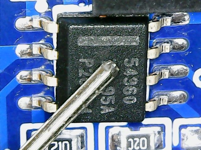
this image was taken after 5 minutes brush with IPA+acetone:
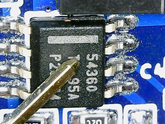
And this is the same board after only 3 minutes in ultrasonic cleaner in IPA:
-
Everything nRF52840@NeverDie i can speak for arduino side im not sure how it works for CircuitPython. virtual hard drive part is only true if there was a bootloader prior to update. im not sure how nordic ships their dongles but i think they dont install adafruit bootloader inside of them :) so you need a fresh bootloader install and it is easy but you need jlink for that. after connecting your jlink to nrf52 open the arduino from menu find jlink for adafruit nrf52 and then just simply click install bootloader and voila it works with arduino.
but then again that usb dongle wont work seamlessly with adafruit bootloader because im sure adafruit has different pin maps you just need to check their pins from variants file and match them on paper to the dongle so when you write your code you know which ones to use, unless theres a seperate variants file specifically made for this dongle. -
Everything nRF52840after abit of looking around and testing i think i made it work at least examples are quite responsive without a single disconnect. i had to add some header files and extra bit of code to every sketch so the knows how to use PA/LNA.
static void pa_lna_assist(uint32_t gpio_pa_pin, uint32_t gpio_lna_pin)
{
    ret_code_t err_code;

    static const uint32_t gpio_toggle_ch = 0;
    static const uint32_t ppi_set_ch = 0;
    static const uint32_t ppi_clr_ch = 1;

    // Configure SoftDevice PA/LNA assist
    ble_opt_t opt;
    memset(&opt, 0, sizeof(ble_opt_t));
    // Common PA/LNA config
    opt.common_opt.pa_lna.gpiote_ch_id  = gpio_toggle_ch;        // GPIOTE channel
    opt.common_opt.pa_lna.ppi_ch_id_clr = ppi_clr_ch;            // PPI channel for pin clearing
    opt.common_opt.pa_lna.ppi_ch_id_set = ppi_set_ch;            // PPI channel for pin setting
    // PA config
    opt.common_opt.pa_lna.pa_cfg.active_high = 1;                // Set the pin to be active high
    opt.common_opt.pa_lna.pa_cfg.enable      = 1;                // Enable toggling
    opt.common_opt.pa_lna.pa_cfg.gpio_pin    = gpio_pa_pin;      // The GPIO pin to toggle

    // LNA config
    opt.common_opt.pa_lna.lna_cfg.active_high  = 1;              // Set the pin to be active high
    opt.common_opt.pa_lna.lna_cfg.enable       = 1;              // Enable toggling
    opt.common_opt.pa_lna.lna_cfg.gpio_pin     = gpio_lna_pin;   // The GPIO pin to toggle

    err_code = sd_ble_opt_set(BLE_COMMON_OPT_PA_LNA, &opt);

}
in this form i like the ble, without pa not so much. theres just big down side which is nrf52840 definitely not hobbyist friendly. next time i may design a quick nrf52832 pa board (this one has regular QFN package) to test with the same setup and compare the results.
-
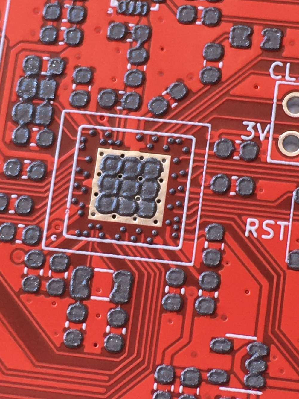
Everything nRF52840@NeverDie i had to use stencil because i cant inspect aQFN soc from outside. as you can see every pin is at the bottom of it and they are very tiny. to make sure theres correct amount theres no other way than using stencil. to be honest i was expecting problems but it was ok :)
-
Everything nRF52840hey guys, i finally assembled my nrf52840 pa board. it was sitting there for quite some time but i couldn't find some spare time to get on with it but here are some experiences i had.
i was worried about this aQFN footprint but it all went well, looks like everything is soldered correctly and i ordered my boards with cheapest HASL instead of ENIG.
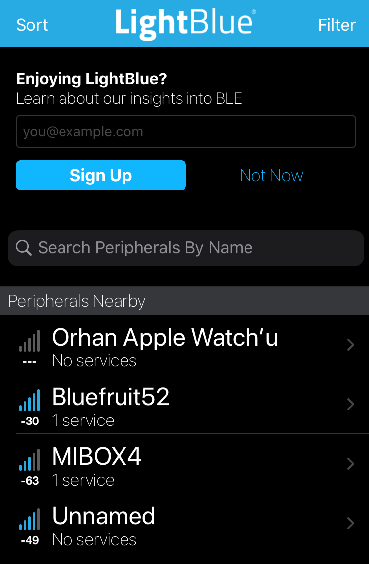
then i uploaded the adafruit feather bootloader to test the bluetooth and it all works ok. i used my iphone 6s as a central device and im not sure if my phone has LNA or PA module inside for bluetooth so it may or may not be better if i use another module like the one i did. this connection is from my module to my phone WITHOUT PA activated at tx power max(8):

and this is after i activate PA chip on board :
and this is with 3 solid walls in between at around 10 meters distance
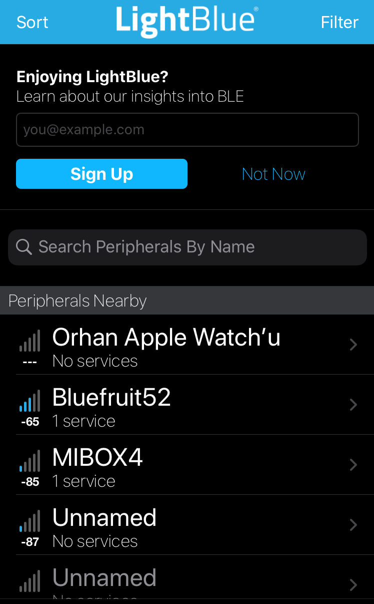
as you can see signal strength is massively different pa bumps up the signal from -87dbm to -30dbm which is probably day and night difference.
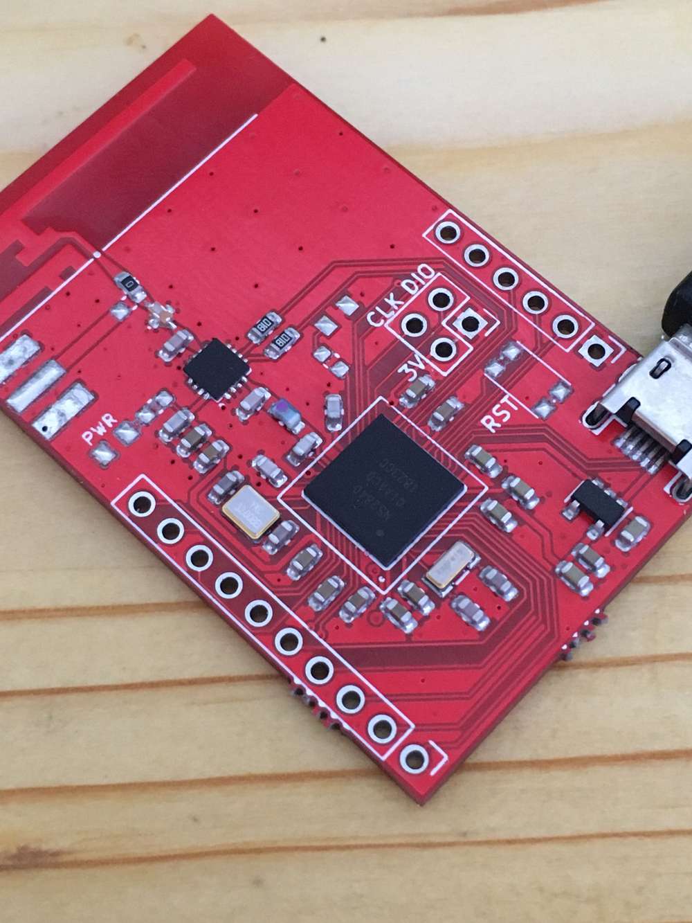
but with this setup you manually have to enable and disable rx and tx pins in order to keep the communication. well im not really good at coding but im going to try make the whole thing automatically because nordic already has this PA assist feature buried inside its BLE core, just gotta find a way to make it work.final board, forgot to add i opted to use pcb antenna but i could switch to external antenna as well i just have to reposition the 0 ohm resistor to use that SMA on the side and then results could get even better:
-
Everything nRF52840@scalz thanks for the input, ive seen they tune it by cutting a length from the longer end but in order to do that i need equipment which i dont have so its going to be a hit or miss :) if it doesnt work well i can use SMA antenna but i think thats the least of my worries with that pcb. I like to experiment and see for myself so even if its wasted its ok :)
-
Everything nRF52840@Mishka i was looking at that long range support of nrf52840 by lowering the data rate to 500kbps or 125 kbps you gain a significant amount of range like 4 fold but it requires a coded PHY which is not available in arduino environment at least not that i know of. adafruit marked it in their to do list but know knows when they gonna implement it probably thats why nrf24's make a significant difference in signal strength when you lower the data rate to 250kbps.
Yes that amplifier draws quite abit of current i think it was up to 350ma when tx is on but ofc it is not on all the time so but still its not for everyone.
i will look into that antenna you mentioned while im waiting for the pcbs thank you for the suggestion!
antenna that i used in the pcb is this one: i read its better than chip antennas but ofc at a much bigger footprint
http://www.ti.com/lit/an/swru120d/swru120d.pdf -
nRF5 action!usb connector is actually nested as far as i can see but it dips 1-2 mm only. weird but it works so its all good :)
-
Anyone cleaning the flux off using an ultrasonic cleaner?to reduce evaporation i saw a guy doing the following method. he fills the container with regular water up to middle mark and then gets some fridge ziplock bags fills them with cleaning solution or just IPA puts the pcbs in the bag locks them and tosses bag into the water filled ultrasonic cleaner. when it finished just takes out the pcbs and locks the bags again for later use until the solution or alcohol is not usable. sounds very practical but i dont have experience with it.
-
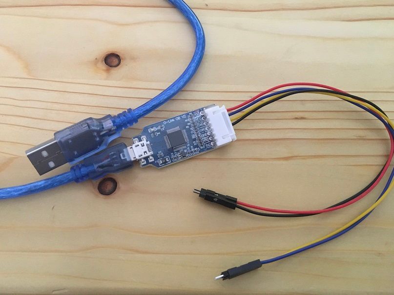
nRF5 action!i just received this little thing, tested it with atmel studio just to flash some M4 boards and it worked nicely. i wanted to update its firmware via jlink(playing with fire) but it didnt let me saying its up to date so its all ok i guess. it only has 4 pins 3v, gnd, swdio, swclk. for $2.50 in total with shipping its a steal :)
-
Everything nRF52840@Jon-Raymond exactly too much in the middle will raise it and bam you have a failed board :)
@Mishka its a wise choice to ask for assembly because of the reasons you mentioned. ENIG is kinda mentioned everywhere for this aQFN footprint otherwise surface might not be even for every single pin and it will result in failed soldering BUT i still went with HASL just to prove them wrong :))
capped via service is expensive so i just went through every single pin to examine and decide if i really need it or is it necessary for it to work and spaced them out as much as i can. i still got plenty, 3 analog pins, 9 high speed digital pins and rest is low frequency pins which are not recommended for high speed operations. it can interfere with the bluetooth signal. nordic specialist approved the design so if everything goes well it should work.
my only worry was the at the bottom side XC1 XC2 pins you can see they are really close to each other i think it was 5 mil but still it was in the capabilities so it went through. i ll see how it goes its gonna be interesting.
and yes i use stencil and a reflow oven.
how do you like the antenna performance of the nrf52840? sadly it doesnt meet my requirements so im trying this pa lna method to see if i can make it work. -
nRF5 action!@Calvin-Khung Well im actually surprised that it still works because people are reporting they might stop working after a firmware update so you might wanna hold back on that other than that it works surprisingly well. i bought another as my back up plan which im expecting it in these days. its abit different than the one i have. this one is much cheaper and looks like jlink edu mini rather than a normal j link with a black box.. i ll see if it works when i receive it, here it is.
https://www.aliexpress.com/item/32669702891.html?spm=a2g0s.9042311.0.0.27424c4d4Fx7g9 -
Everything nRF52840i just gave this pcb to a production, it has nrf52840 and pa/lna module, 3v3 LDO on it, practically a stand alone board with nrf52. i did not include a battery connector or charger because its for prototyping. i copied the front end part from my nrf24 modules so if i can solder it should work smoothly. tho this aQFN footprint looks very intimidating :) some of the tracks and gaps are at the manufacturers design capability tolerance limits so lets see if they gonna accept it.
-
nRF5 action!i use $10 replica Jlink from aliexpress works ok with the latest firmware without an issue. i use it just to flash bootloaders to cortex m0-m4 and nrf52's but it should work for any task that a genuine jlink can do.
-
Everything nRF52840@Jon-Raymond selling them was not my intention but i have around 8 bare pcbs and 2 built ones. i can fix you up with one of those if you want to or i can cook totally brand new one up to you.
-
Ebyte nRF24 module comparison (2020)@sola they can do the job depending on your environment. in my experience if theres an obstacle like if your module is in a box if modules are not in line of sight pa lna solves the signal issues. otherwise those without pa are ok too. one fatal mistake is to put some metal or lean the antenna back against a ground plane. oh man that totally kills the signal :) its a newbie mistake but its worth mentioning.
-
Everything nRF52840@NeverDie Well BT840X has built in FEM SKY66112 if im not mistaken, thats why you are getting good results but how did you make it work in the code. Because for TX and RX you need to tell the NRF when to listen and when to transmit so the FEM can flip switches inside and work its magic.
Tomorrow i will try a remote application where client transmits analog read data every 50ms and reports it to the peripheral device, i will put it in a plastic box and wrap my hand around it and see how many packets it will drop tho im really skeptical after today.