You need a Pin Vice (or vise if you're across the pond and want to butcher the Queen's King's English)...
Pete.
You need a Pin Vice (or vise if you're across the pond and want to butcher the Queen's King's English)...
Pete.
@skypn I have no idea how this fits-in with the MySensors forum - if at all.
I find it difficult to justify the time, cost and poor quality results of home milling PCBs compared to the results you get from the likes of JLCPCB
@zebmina Personally, I don't like the 433 Tx/Tx modules that use tuned coils, I prefer the ones with a crystal like these:
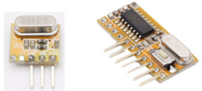
They are much less noisy in my experience.
Also, I'd power your circuit from a couple of 1.5v batteries if I were you, one less source of noise.
You don't appear to have an antenna connected to your Rx module, and that may make quite a difference.
This is the circuit that I used:
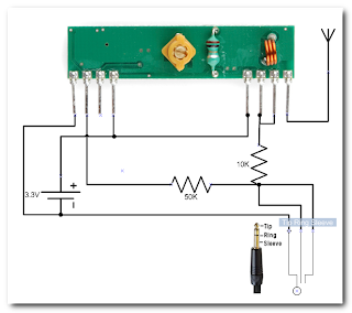
but you should note that the faint blue writing in the bottom left that says (left to right) "Tip/Ring/Sleeve" is incorrect. It should say "Sleeve/Tip/Ring" so that the leftmost connection (-ve on the battery) is the sleeve, and the Tip/Ring connections are both connected to the data pin on 433 module, via a 10K resistor. The other resistor is 50K in case you're having trouble reading the writing.
The other thing to look out for is that it's plugged into the correct socket on your PC (Aux) and that you have the correct input selected in Audacity and that your PC's sound source/mixer settings are correct.
Once I started capturing data I was fooled by the fact that my controller sent two different waveforms for some buttons, one when the button is pressed and another when it is released. It was the "pressed" waveform that needed to be decoded, then repeated 4 times for the blinds to respond to it.
More info here:
https://forum.mysensors.org/post/91706
Pete.
There was a similar discussion over on the Blynk forum a few years ago, which might be worth reading....
https://community.blynk.cc/t/gas-stove-safety/17331
Pete.
@Jasonkeel obviously one is rigid and the other is flexible!
Flexible PCBs are found in things like RGB LED strips, where components need to be mounted to a flexible substrate, whereas rigid single/multi layer PCBs are used for the majority of PCB designs because you want the substrate material to be rigid and easy to mount in enclosures.
Mounting discreet non-flexible components onto a flexible substrate has its issues, as the pads that connect to the components can tear if the pcb is bent through too tight a radius.
Pete.
@mmartins if you re-read what I wrote, you’ll see that the Raspi-Rollo software has an Arduino sketch to identity the codes. I ran this on a NodeMCU, so it should work on an ESP32.
If you need to use Audacity then the process is well documented in the links earlier in this topic.
I have three blinds and they all use independent remotes and each blind has its own codes.
I’m not sure how my codes will help with yours, but here are the codes for one of my blinds:
Up
1011101000110000111011101001000100010001
Stop
1011101000110000111011101001000101010101
Down
1011101000110000111011101001000100110011
If your blinds do actually use rolling codes the I don’t think you’ll be able to control them the same way that I do.
Pete.
@ssuckow what you’ve posted seems to be a good match for the original.
I’m wondering, based on your other comments, if your blinds need the message repeating several times (with my blinds it’s 4 times) or if the initial message is a sort of ‘stand by to receive a command’ instruction that needs to then be followed by the command message (maybe multiple times?).
Try quickly stabbing at the remote control button whilst recording in Audacity and look at the bigger picture. This might give you a bigger picture of the complete command set that the remote is sending when a button is pressed.
Pete.
I was watching something on TV the other day where someone was running a guest house in France and they had to have an audible alarm that sounds whenever someone falls in the pool. I guess it's intended for child safety.
The off-the shelf system that they added used an air pressure switch as the sensor and a key-pad to disarm the alarm. It re-arms after a certain time if there's been no activity.
Most washing machines (at least the front-loading variety) use an air pressure switch to sense water level and this acts as an interlock to prevent the door being opened when there's still water inside. These switches have a plastic tube and n internal diaphragm. When the end of the tube is below the water it creates a positive pressure in the tube, which distorts the diaphragm and operates a microswitch. Sounds a bit clunky, but they are very reliable. A switch of this type could be used to detect when the water level falls below a certain point.
The other thing is that most pools have an auto-fill system that operates like a toilet cistern. The problem with these is that if you have an undetected leak you can end-up with a large water bill before you know that anything is wrong. I'd add a flow-rate sensor on the inlet to the auto fill supply to see how much water is being used. It would keep the pool topped-up and record how much water has been used, and alert me if that exceeded certain limits - maybe with an electrically operated valve to shut-off the supply in those situations.
Pete.
@neverdie If you want easily removable and reusable moulds then go for silicone moulds. These can be either the type specifically sold for epoxy moulding, or silicone trays for baking (but don't let Mrs NeverDie catch you!).
The most economical way of using epoxy is to but the large containers of liquid and hardener. The epoxy adhesive (Araldite type of products) tend to be more viscous and harder to mix properly in large quantities.
Take a look on eBay at what's available.
There are also other potting compounds and rubberised paint products that are specifically designed for waterproofing electronics and may be a better option. Search for Plasti Dip or TRV Tropicalised Varnish.
Pete.
Hi guys,
I realise that this is quite an old thread, but i found it a useful source of info when looking for a solution for my 433MHz problem, so I thought I'd share some of my findings...
We have a holiday home in Spain and it has some external 'awnings' that extend over the windows to provide shade from the sun. In Spain these are called Toldos. They operate using tubular motors controlled using 433MHz remote controls – one remote for each awning, three in total. I'd tried all the regular methods to sniff the 433MHz protocol, but none of the standard Arduino libraries would even acknowledge that the remote was sending out any sort of signal. Other remotes, such as garage door openers, PIR detectors etc work fine with my sniffer, so the hardware/software I was using is good.
I eventually resorted to using my sound card and Audacity software to capture the transmissions from the remote controls and this work surprisingly well (I'd tried every digital approach you can imagine up to this point, including a logic analyser, and was reluctant to try the analogue approach but wish I’d trued it earlier).
What I discovered is that when I press either the UP or the Down buttons on the remote, it transmits a timing pulse followed by 40 bits of data. At first I thought that this sequence was repeated 8 times, but I eventually realised that one 40-bit code was used for the first 4 repetitions of the data, followed by a different code for the next 4 repetitions. I later realised that whenever one of these buttons is pressed, the initial 40 bit code is transmitted continuously then the other code is transmitted 4 times when the button is released. When the button is pressed quickly I just get the 'Pressed' code 4 times followed by the 'Released' code 4 times.
The Stop button works slightly differently - only one code is used and this is transmitted at least 4 times and will continue to be transmitted as long as the button is pressed. (in other words, the Stop button has a 'Pressed' code, but not a 'Released' code).
It's actually the 'Pressed' code for each button that controls the awnings. The 'Released' code doesn't seem to serve any function with my awnings.
These 'Released' codes really confused me to begin with, as I when I checked two different bursts of data from the same button using Audacity, I was getting different results. This was obviously because on one occasion I’d picked one of the ‘Pressed’ codes to analyse, but on the second occasion I’d inadvertently analysed a ‘Released’ code. At first I’d thought the analogue capture process was unreliable, but then I thought that maybe some sort of rolling code system was being used. I eventually realised what was going on, but not until I'd spent quite a bit of time cursing the remote control and the PC.
I was able to replicate the transmitted code fairly accuracy using a version of @peashooter's code (thanks!) and this worked well
I’m repeating the ‘Pressed’ code 4 times and it seems to work very reliably.
As well as being able to control the awnings using an Arduino/ESP8266 transmitter, I also wanted to be able to use the existing handheld remotes, so to be able to understand the current position of each awning I needed a way of receiving the commands from the remotes and using them to keep track of each individual awning. This bought me back to the original problem of not being able to find a way to listen to the 433MHz messages from the remotes using any of the current Arduino libraries.
In started delving into the idea of modifying the RC-Switch library, now that I knew the timing characteristics of the signals. At that point I stumbled across this small library:
https://github.com/bjwelker/Raspi-Rollo
It has an Arduino sketch that is written to identify the codes that are being transmitted by remote controllers for blinds, so that these codes can then be used to control the blinds using a Raspberry Pi.
When I ran the Arduino sketch it immediately produced results from my Awning remotes – If only I’d found this earlier!
The results it gives are in a “Quad Bit” format, but when I modified the code to print out the raw received codes they were identical to the results I’d obtained from Audacity.
I’m not interested in using a Pi to transmit the codes to the blinds, and this wasn’t needed anyway, as using @peashooter's code I already had a transmission solution. I’m now in the process of fine-tuning the code that tracks each blind’s position based on the commands that are sent from either the hand-held remotes or my transmitter. The position is simply based on time between the start and stop transmissions and the known time that it takes to fully extend each awning.
The primary reason for wanting to control the awnings is that when it gets windy, I want to be able to automatically retract them. I’m using data from a weather station to monitor the wind speed and if it meets the criteria (very strong winds for a short period, or not quite so strong winds for a slightly longer period, then the awnings will be retracted (assuming that they’re extended of course). I’m also automatically retracting them when it gets dark, as it’s easy to forget to do this and a bit cumbersome to walk around and do all three awnings using the separate hand-held remote controls.
Here’s some pictures of one of the remotes:
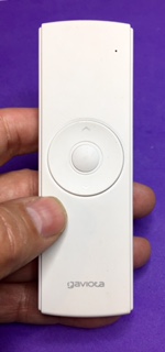
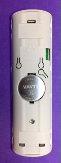
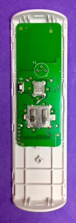
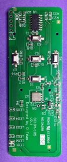
The brand name on the remote is Gaviota and the circuit board says “Designed by D Team” “DC104/105” “V2.1” and “No.DA288”.
Here are what the awnings look like:
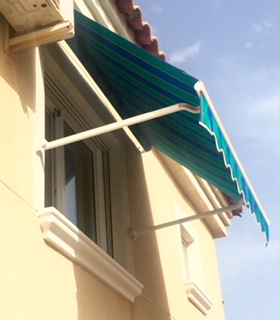
I have no idea what the brand name is on the tubular motors, as they’re hidden inside the mechanism.
Hopefully this saves someone at least some of the pain that I’ve been through to get to this point.
Pete.