@hek I am seeing a lot of st=fail on my nodes. I have added a 4.7uF capacitor between ground and VCC but that did not help. What should I try next? a bigger capacitor? I am using an iphone wall charger as power source.
Thanks!
@hek I am seeing a lot of st=fail on my nodes. I have added a 4.7uF capacitor between ground and VCC but that did not help. What should I try next? a bigger capacitor? I am using an iphone wall charger as power source.
Thanks!
YES!!! That was it! I got both relays powered from the external power supply now and everything seems to be working fine.
Thank you all very much!
@Nuubi
This is how I have my connections:
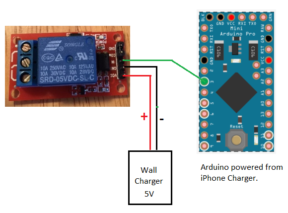
Is there anything wrong with it?
Thanks!
Thanks for the heads up. But I tried 9v and 12v and no luck! They only click when powered directly from the Arduino and they stop working after a few hours.
@ServiceXp
What kind of power supply do you use to power the relays? I've tried several different options (iPhone charger, iPad charger, and various other 5v power supplies) but no luck. The LEDs on the relay turn on, but it doesn't click. Would you have a picture of one of your relays so I can see your setup?
I also tried following the advice from @BulldogLowell and powered the relays from the VIN pin instead of the Arduino 5v output, but I had the same problem. The relay worked for a few hours, then stopped working.
FYI: I am using a relay with optocoupler just like the one posted in the link above. Maybe I just got a batch of bad Arduinos from China?
Thanks!
So my problem is definitely that the Arduino is not strong enough to power the relays. When the relays are not powered by the Arduino, my sensor communicates with the gateway just fine. It's been on for more than 24 hours now and still communicating fine.
I found this somewhere else, and I think it's exactly what was happening:
"if you draw too much power from the +5V, the thermal protection circuit on the voltage regulator will trip and the whole Arduino will shut down"
So I just need to find a way to power the relays from an external power source. Has anyone done that?
I've tried several different power sources, and with all of them the relay LEDs turn on but it won't click when turn it on/off. I even tried powering the relay from another Arduino just to make sure the voltage was right, but still no luck.
Thanks!
@sundberg84
Mine says SRD-05VDC-SL-C on top. Im pretty sure this is a 5v because it works fine when powered from the Arduino 5v output. I just wanted to connect it to an external power source because I have two relays connected to my Arduino now and that might bee too much for it to handle.
I tried the ipad charger and still no luck. I also tried another power supply with output 2.5A @5V and it didnt work. Now I'm just curious, if I need a bigger power supply to power the relay, how come the Arduino is able to power it from it's 5V output?
Thanks for the help!
@hek said:
Also try feeding the realys directly from the 5V input from the charger.
I tried doing that, but when I feed the relay with the external 5v supply they wont work. The power light turns on and looks good, but when I click on/off in the UI the relay wont switch. Do I need to do anything special to power the relays directly from the charger?
Thanks!
@BulldogLowell
That is a good idea. But if I do so, can I choose which relay I want to turn on/off from the UI? The water pressure here is not very strong, so I need to turn on only one irrigation channel at a time. But I will give that a try anyways!
Thanks!
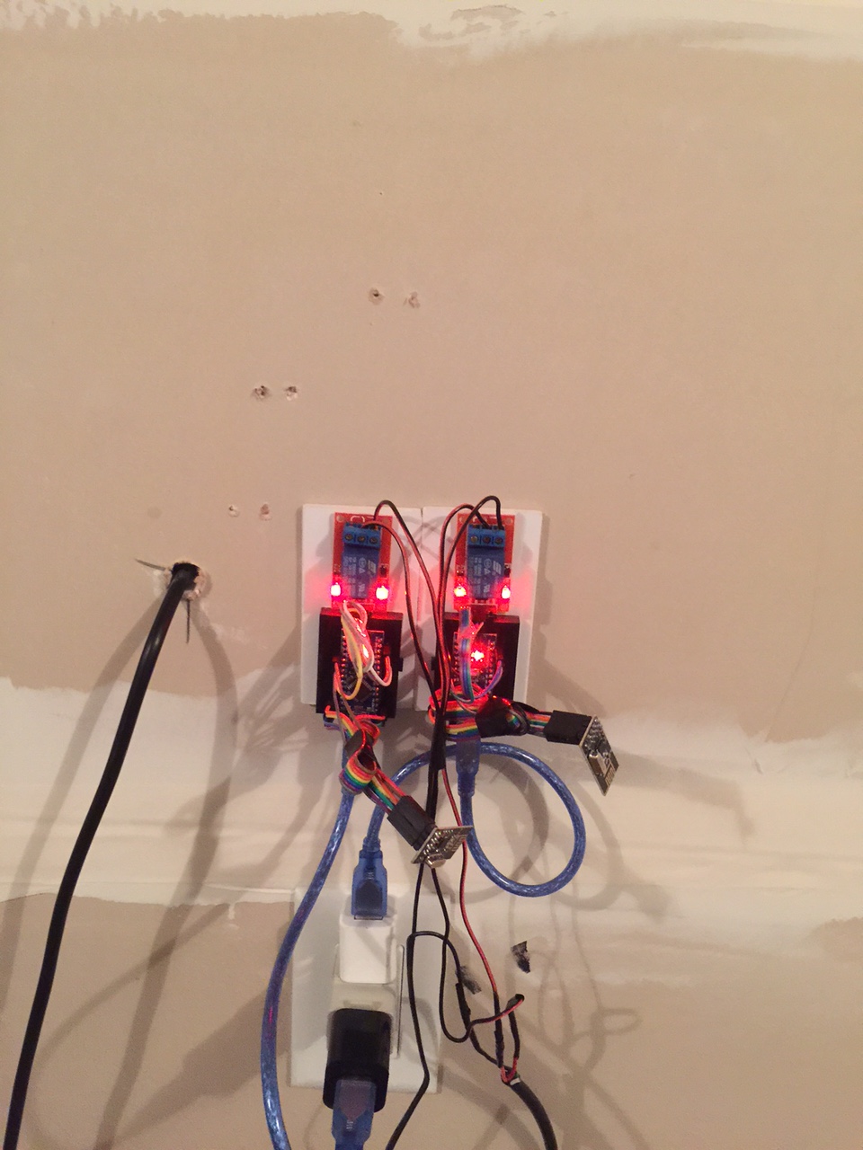
So I have two relay sensors that I use to control my sprinklers.
They sit in my garage on the wall right by each other as displayed in the picture. When I restart the sensors they work just fine for about 20 minutes, and then for some reason they stop communicating with the gateway and I cant control them from the Vera UI anymore. I click the ON/OFF buttons and nothing happens.
Has anyone had this problem before? I wonder if the fact that they are sitting right by each other has anything to do with it. Maybe the radio receivers are interfering with each other?
I am using Arduino nano and MySensors Library 1.4. Any help is appreciated!
Thanks
Thank you for the reply! My Relay does not have the labels you mentioned above, that's why I was confused. But I figured out that if I connect the Hot wire in the middle pin it will switch between the other 2, so that was helpful and is exactly what I needed I guess.
You are correct about not being able to tell the state of the light, I didn't think about this. Maybe if I connect a light sensor to my Arduino I could send back the state to Vera based on what the sensor tells me instead of the state of the relay? I'm just not sure if this would work during the day when the windows are open, the sensor might think the lights are on if there is enough sun light in the room.
Anyways, thanks for the help. I'll keep playing with this and see what I can come up with.
This is what I want. One of the switches bellow is a regular light switch, and the other one would be a relay controlled by my Vera.
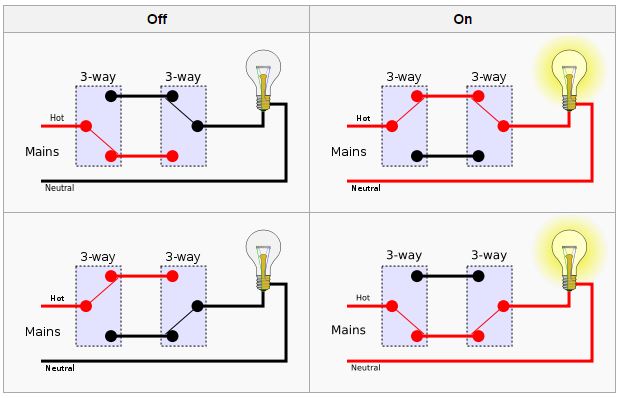
So, filling out your truth table:
Manual switch On, Control On ==> Lamp ON
Manual switch On, Control Off ==> Lamp OFF
Manual switch Off, Control On ==> Lamp OFF
Manual switch Off, Control Off ==> Lamp ON
Notice that no matter what the combination is, once you flip one of them, the lights will change the state.
I understand the concept, just don't know how to wire the Relay in this situation.
Thanks!
I would like to use a Relay Switch to turn some lights on and off, but I would like to install them in such a way that the existing light switches would still work to turn the lights on and off manually. I wanted to integrate the Relay as a "3 Way Switch" using a traveler wire, so I can turn the lights manually and turn it off with the relay and vice versa, but wasn't sure if the Relay can do that.
Has anybody here tried something like this? If so how did you integrate the Relay into your system?
I usually only use 2 of the 3 pins available in the relay, and I was wondering what the third pin is for. Is the third one where I would connect the traveler wire?
Thanks!
If you go to Github and download the zip with all the files, you dont need to copy and paste the code and save with the correct extension.
you can use this link to download the zip:
https://github.com/mysensors/Arduino
Have you looked in the debugger to see if your Gateway initialization is successful? I also had problems getting my Vera to recognize my Gateway, and that was because the Arduino I was using was one of those clones from china. When I bought a Genuine Gravitech Nano, it worked right away.
I also had problems to get my Vera to recognize these Chinese clones. I ended up buying a genuine Gravitec Arduino Nano to use as a gateway and everything works fine now. The clones work just fine for the sensors though, just not for the Gateway.
I have been using the Vera Mobile UI7 on my iPhone to control my Veralite, but I've been having problems making it work with my Foscam cameras, and also with the Servo Sensor to control my blinds.
I'been thinking about using a different App and was wondering what you guys use out there. Any suggestions?
Thanks!
@ServiceXp
Yeah it was really expensive. But I had tried with 3 different types of clones and none of them worked. You were lucky!
@ServiceXp
Yeah it was really expensive. But I had tried with 3 different types of clones and none of them worked. You were lucky!
PROBLEM SOLVED
So after trying a thousand different things I decided to bite the bulled and bought a Genuine Gravitec Arduino Nano, loaded the Serial Gateway Sketch into it and BOOM! Worked on the first try. My Vera recognized it as soon as I plugged it in.
For all you guys having problems with Serial Gateway I recommend buying a Gravitec Nano to use as a Gateway. The clones work just fine for the sensors, but not for the Gateway.
This is the one I bought:
http://www.ebay.com/itm/400306780486?ssPageName=STRK:MEWNX:IT&_trksid=p3984.m1497.l2648