I'm wondering what the minimum input voltage is. The description only says max. 6.5V input voltage from the battery, but does not say what the minimum is. Both the nrf24l01+ as well as the atmega328P work with 3.3V, so if I use three AA batteries, that should be fine, right? I suppose using two AA batteries is not enough?
reinhold
Posts
-
💬 MySensors Stable Node -
💬 Multi-Sensor: Temp/Humidity/PIR/ Leak/Magnet/Light/Accel@Omemanti, thanks for the pointer. Unfortunately, this seems to be a hardware problem of the NRF52* boards, not of the NRF51822-04 that is used in NeverDie's board.
Is there any way to find out which peripherals are enabled while the nrf51 is sleeping? I tried googling and also looked at the openocd documentation, but couldn't see any reference to reading out the which peripherals are turned off and which are running while the nrf is in deep sleep. (I'm using a cheap Chinese ST-link V2 dongle to program the nrf via SWD).
-
💬 Multi-Sensor: Temp/Humidity/PIR/ Leak/Magnet/Light/AccelHi,
What is the power consumption you get with this board and i2c sensors? I built several boards and measured the consumption using a INA219 sensor (lowest resolution is 0.1mA). Without any I2C sensor initialized, it shows a power consumption well below 0.1mA (i.e. it always shows 0.0), but as soon as I use an I2C sensor, the consumption during sleep increases to 0.3mA, which drains the battery faster than desired for a battery node...I tried it with several different implementations / sensors, and always got the same result:
- MyBoardNRF5 with BME280 (Adafruit library), sketch adapted from the one supplied with this board
- MyBoardNRF5 with BME280 using NodeManger
- MyBoardNRF5 with VL53L0x using NodeManager
- Custom board in Arduino IDE derived from Sandeep Mistry's generic 51822 board, with either of the above sketches
Is there anything special I need to do to get power consumption with i2c sensors down to the desired single-digit-µA-range during sleep?
-
💬 PogoPinsYes, 1.27mm pitch should be possible with pogo pins (I have never done them myself, though).
You need to buy the smaller pogo pins (diameter 0.68mm). Some examples by other hackaers can be found e.g. at
- http://blog.spitzenpfeil.org/wordpress/projects/the-pogo-key-1-27mm-avr-isp-pogo-pin-adapter/
- http://blog.spitzenpfeil.org/wordpress/2013/11/12/the-pogo-key-1-27mm-avr-isp-adapter-take-ii/
- http://blog.spitzenpfeil.org/wordpress/2013/07/05/tiny-pcbs-vs-large-isp-headers-pogo-pins-to-the-rescue/
- https://www.tindie.com/products/ElectronutLabs/pogoprog-model-c-pogo-pin-programmer-swd-2-pack/
-
💬 NodeManager@user2684 Right, thanks for pointing this out. I mixed up the child name that was sent to the controller (which can be changed by e.g.
void before() {
 ...
  doorLeft.children.get(1)->setDescription("Door Left");
  doorRight.children.get(1)->setDescription("Door Right");
  node.before();
}
) and the sensor's _name field, which is printed to the debug output. That "DOOR" debug output cannot be changed without subclassing. But as this is just debug output, it's just a minor nuissance.
-
💬 NodeManager@iteafreely I don't think there is a limit of one sensor per type, not even for interrupts like door sensors. You just need to make sure you are using different pins and different child ids for the two magnetic sensors. I'm using 8 analog sensors (MQ-... gas sensors) on eight different pins on the same node and it works just fine.
Of course, if you need some interdependence on what the two magnetic sensors report, then you must follow @user2684's suggestion of creating a custom sensor (a C++ class derived from an existing sensor class).
But if you simply want two independent magnetic sensors (for each of the ends of your sliding door), then you can simply create two instances of SensorDoor on two different pins (here pins 3 and 4) and different hardcoded child_id (1 and 2 in this case):SensorDoor doorLeft(node,3,1); SensorDoor doorRight(node, 4,2);Unfortunately, both of them will report to the gateway with name "DOOR" (and there's no way to change it without subclassing SensorDoor), but they will have a different child_id 1 and 2 to distinguish the two values sent by the node.
You can then use your smart home controller to handle the two door sensors like one.
-
Trying to bitbang i2c oled screen, using SSD1306Ascii libraryIf you insist on connecting the analog sensors to the arduino and switch to a software I2C implementation on non-hardware I2C pins, you might simply extend the SSD1306Ascii library. It currently has classes for the SSD1306 over the AVR hardware i2c, another class for generic Wire implementations (not tailored to atmel chips; e.g. I'm using it on nrf51822), and the SPI devices.
Looking at the SoftwareI2CLibrary docs, it appears that they even provide a Wire interface (SoftWire.h), so you might even get away with the SSD1306AsciiWire class for the OLED.
If that does not work, you'll have to write your own software I2C implementation for the SSD1306Ascii class (e.g. takt SSD1306AsciiWire, rename it to SSD1306AsciiSoftI2C and adjust it to use the SoftwareI2C library for all I2C communication).)
-
Trying to bitbang i2c oled screen, using SSD1306Ascii libraryAnother idea might be to connect all analog sensors to I2C Analog-digital converters like the ADS1115:
https://www.aliexpress.com/store/product/I2C-ADS1115-16-Bit-ADC-4-channel-Module-with-Programmable-Gain-Amplifier-2-0V-to-5/324775_32903062908.htmlAs you can hook up multiple devices to the same i2c bus, simply attach the OLED and two of those ADS1115 boards (apparently you can assign up to 7 different I2C addresses to the ADC boards...) to the I2C bus.
-
Cannot run MySensors on RPI 3I've been running the Ethernet gateway (port 5003) on my raspi without issues for several months now.
@kkanedaa It looks like the development version finally works with your nrf module. Regarding the MQTT connection refused: Are you sure your MQTT broker does not need a username and password?
-
What did you build today (Pictures) ?@gohan I'm using the SSD1306Ascii library, which does not use a display buffer and does not support graphics, only text. The drawback is that to prevent screen flickering, you have to manually clean each line of text to the EOL. Otherwise letters that are not overwritten by new text will not be cleared. See my PR for NodeManager how it works. With my approach, there is absolutely no screen flicker, the display updates properly and the memory requirements are minimal (the library docs say its 53 bytes)
-
What did you build today (Pictures) ?Today I finished the coding for my prototype of a laser distance sensor (intended to measure the water level for my automatic in-door flower watering pump). The sensor is connected via I²C and has sleep pin.
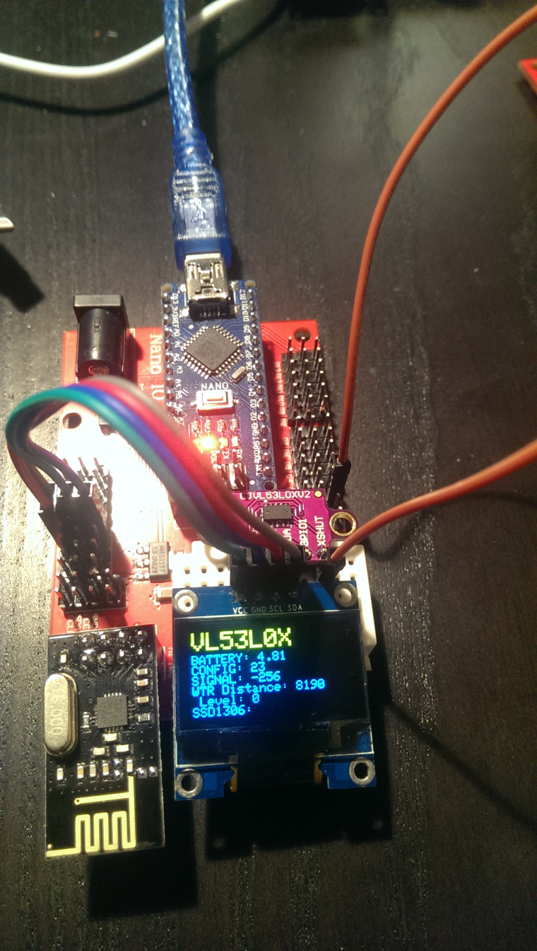
The most work was implementing support for the VL52L0X laser distance sensor and for my 128x64 OLED display to NodeManager (PRs submitted as https://github.com/mysensors/NodeManager/pull/244 and https://github.com/mysensors/NodeManager/pull/245).
The OLED is really useful when prototyping sensor nodes. Out of the box, my NodeManager OLED implemention will display the values of all attached sensors without any coding. Simply create the DisplaySSD1306 after all other sensors, and the OLED will pick up and display all sensors automatically...
Once everything works, of course the OLED is not desired for the water level sensor running on batteries...
-
💬 NodeManager@user2684 Thanks for the spreadsheet with your memory footprints. Are these the sketch size and the free memory that the compiler reports? Or do you measure them when running the sketch (i.e. including all dynamically allocated variables in SRAM)?
Also, one problem you don't seem to have covered is heap fragmentation. Particularly your new List class seems to be prone to heap fragmentation with a large number of sensors: each time a sensor is added, the list needs to re-allocate the memory for its pointers. The old memory will be released, but it will remain as a hole in the memory, where new variables might be allocated. However, the next time you add an element to the list, the new pointer array can probably not re-use some of those freed holes.
I'll provide a PR (https://github.com/mysensors/NodeManager/pull/247) that adds an allocateBlocks(count) method to the List, which can be used in the sketch and in the sensor's onSetup methods to pre-allocate the required sized. In turn, the _preAllocBlocks member does currently not serve any purpose, and I don't think it's really required functionality. In my eyes, it's more important to ensure that at a certain moment the required memory is allocated. It is not neccessary to keep a minimum nuber of blocks allocated at all times.
For a node with 10 physical sensors (and maybe one or more built-in sensors), this will save at least 22 bytes (1,1% of total SRAM!) and probably reduce heap fragmentation by quite a bit.Another are where >22 bytes can be saved is the power manager. None of my nodes makes use of the power manager, yet each sensor needs to keep a (null) pointer to a power manager. Providing a compiler #define NO_MODULE_POWER_MANAGER can exclude everything PowerManager-related from compilation and save one pointer per sensor and node, i.e. with 10 sensors you'll save another 22 bytes (1,1% of total SRAM!) I'll provide a PR for this, too: https://github.com/mysensors/NodeManager/pull/248
Apart from that, I simply stripped down the SensorMQ class and removed all configurability for my own use (don't worry, I won't submit this as a pull request... it is simply meant to squeeze the sketch onto the pro mini with the boards that I have already built).
BTW, the SensorConfiguration is no problem as far as SRAM is concerned (it just adds the normal SRAM footprint of a Sensor instance): It has no class members of its own. Only the flash size is considerable, but for me this is not the issue, I'm running out of SRAM. -
💬 NodeManager@nca78 Two more things popped up with the latest development version of NodeManager:
- In NodeManager.ino: function void before(): The sample code to set the child id of a child is sht.children.get(1)->child_id = 5, but that does not work, because at that point the children are not yet even generated. They are created by the node.before(); call at the very end of the function... So, currently this will not assign any new child ID and the default IDs will be used. I have not checked in detail whether calling node.before() at the beginning of the before() function and then assigning child_id to the children will solve the issue. From a quick look at the code, it might work...
- I'm trying to implement an OLED display, where the node would wake up every 5 seconds, take a measurement and display it on the OLED. But the report interval to the MySensors gateway should only be 10 minutes. I thought that
node.setSleepSeconds(5); node.setReportIntervalMinutes(10);would be the correct way to setup NodeManager to take measurements every 5 seconds, but only report it every 10 minutes to the network. Unfortunately, Sensor::loop(MyMessage* message) seems to immediately return without measurement if the reporting timer has not elapsed. Somehow I don't understand that logic. Why have different sleep and reporting intervals when measurements will only be taken at reporting intervals anyway? I would expect measurements to be taken with the sleep intervals (e.g. to calculate an average over the whole reporting interval) and report back to the network using report intervals.
-
💬 NodeManager@nca78 Thanks for the suggestion to use the blue pill STM32 boards. I haven't thought of it (I only looked at the ESP8266, but that has only one ADC). I have a few lying around here, but never got around to trying them, as I first need to burn the bootloader. It looks quite promising, but the boards are huge, so I'll need to enlarge my PCB...
The need for a 5V->3.3V regulator is no issue, as the NRF24 already needs 3.3V. The 5V analog level of the MQ sensors will need some converter (the analog ADC inputs are marked as non-5V-tolerant...), but then in turn I can get rid of the voltage dividers for the PMSA003. The larger issue seems to be the connection of the nrf24, which takes away 4 ADC pins, so there are only 6 ADC pins left, while I have 8 analog sensors :(Still, for now I have the PCBs with the ProMini, so I'll try to strip down the Sensor or SensorMQ classes for my own use.
-
💬 NodeManager@user2684 Thanks a lot for the architecture change, which makes a lot of sense conceptually.
Unfortunately, it appears to use more memory than before. I'm working on an air quality board with eight MQ sensors, an MH-Z19 CO2 sensor and a Plantower PMSA003 particulate matter sensor. In previous development versions (1.7-dev, before today), the eight MQ sensors and the MH-Z19 worked fine, but now after your big merge of #229 the sketch appears to run out of memory after adding the child of the sixth MQ sensor. Do you see any chance to optimize for memory?
Old sketch (using a previous development version of NodeManager, without the PMSA003; 155 bytes left after all nine sensors are fully initialized): https://github.com/open-tools/NodeManager_GasSensor/tree/master/NodeManager_GasSensor
New sketch (using the latest version of NodeManager, plus a PMSA003): https://github.com/kainhofer/NodeManager/tree/GasSensor
That sketch runs out of memory with the sixth MQ sensor (I added debug output with free memory at a lot of spots). Of course, I have commented out the PMSA003 completely to have a correct comparison.FWIW, the sketch is for this board: https://github.com/open-tools/NodeManager_GasSensor/blob/master/images/IMAG2267.jpg
-
What did you build today (Pictures) ?Finally got the PCBs from AllPCB.com (cost 5 Euros and took a total of 7 days from order submission to free DHL delivery to Europe!!!) for my own MySensors Arduino Pro Mini prototyping board. Unfortunately the soldering iron broke during my assembly, so it's not fully finished and I couldn't test it yet, either...
This board is inspired by the Nano IO shields that are offered on AliExpress and improves it further for my needs (and switched to the Pro Mini instead of the Nano).
- Each analog and digital pin of the Pro Mini has its own VCC and GND pins,
- the board also provides its own voltage regulator, solder pins for by NRF24L01+ and RFM69H are provided (plus the 5V->3.3V XC6206 regulator),
- either a tiny 55-pin breadboard or three I²C connectors can be placed on the board.
- One can also use PogoPins instead of soldering the Pro Mini (or headers for it) to burn the bootloader or change fuses on the Pro Mini via the ICSP connector.
All design files are available on GitHub: https://www.openhardware.io/view/538/Arduino-Pro-Mini-IO-Shield
-
CNC PCB milling@neverdie For Austria the threshold for import tax (=VAT substitute, 20%) is 22 Euros (value of the goods, excluding shipping and insurance costs) and for additional customs duties it's 150 Euros.
-
Experiences with arduino Mega in a small package(Mega2560-CORE)? Alternative arduino with more memory?(I know this post is off-topic regarding the original request... Sorry for that)
If your concern is mainly about connecting the radio to the arduino, then I can warmly recommend one of those "Arduino nano IO shields":
https://www.aliexpress.com/item/For-arduino-Nano-Terminal-Expansion-Board-Adapter-IO-Shield-Electronic-Circuit-328P-w-XBEE-nRF24L01-Socket/32841357885.htmlYou just plug in the nrf24l01 (I'm using a small adapter PCB to use the SMD version with the pin header) and the nano and you are ready to go. Also comes with a connector for a 9V power adapter (which I needed for the gas sensors drawing 100+ mA). It also has the four pins for I2c (VCC, GND, SCL, SDA) and Serial (GND, VCC, Tx, Rx) next to each other, and it provides +5V and GND together with each in-/output pin.
To make prototyping even easier, I unsoldered (or broke off) the small female pin headers for the xbee and used two-sided duct tape to add a tiny breadboard instead (where I simply plugin in I2C devices like an OLED or a sensor):
https://www.aliexpress.com/item/7pcs-Mini-55-Points-Breadboard-Solderless-Prototype-Tie-point/32661906252.html -
💬 NModule MiLight bridge shieldHi nca78, nice idea to implement a MiLIght bridge shield. Did you get the PCB back from the fab and try the shield? Does the board work properly? Do you plan to add a description of the board and some code?
Thanks, Reinhold -
How to interface MySensors with a 24V humidifier?For the mysensorization of my air humidifier, I'm trying to interface the arduino with the 24V circuit of the humidifier.
I have some rought schematics in mind, but as I have practically no experience designing electronic cirvuits, I have no idea whether there are better solutions. So I desperately need some input from someone with more knowledge in circuit design. I would be very thankful if you could give me some feedback on my schematics as detailled below.Basically, the questions are how to best convert 24V to 5V/3.3V to power the arduino, whether a MOSFET is the best way to emulate a button press and whether voltage dividers are the correct approach to detect a button press and a burning LED.
The humidifier has the following items that I'm interested in:
- Power button (simple press)
- Switch to detect an open enclosure
- LEDs for Power On/Off and for Error
How to tap into the electronics of the humidifier
The PCB of the humidifier is mainly covered by a large motor, so tapping directly into the microcontroller is not an option (which is also covered by the motor; I can only see the last few characters: 1933, so it is probably a PIC16F1933). However, the control panel (with control buttons, LEDs and also the 24V power jack) is connected through a 10-pin ribbon cable, where I can easily place my own pcb. The ribbon cable provides +24V, GND, and the control buttons connect directly to GND, while the leds connect to +24V. Here's the schematic of the humidifier's existing control panel and the existing connector, where I want to interface:
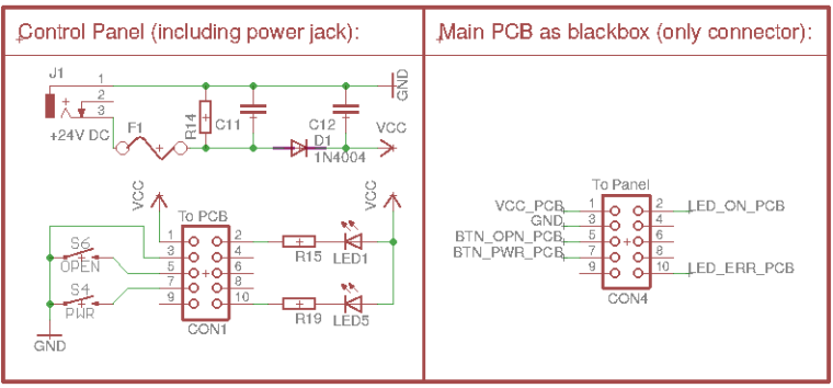
What I am interested in:
- Emulating the Power button from MySensors
- Detecting the Open button (case open warning!) from MySensors
- Detecting which LED is on (to determine state and/or error)
- (Potentially, turn on the error LED from MySensors node, but that's for future use)
All lines of the cable run a voltage of up to 24V (some have ~19-20V measured with a multimeter), so I can't directly feed them into the Arduino.
So, my issues now are:
- Powering the arduino from the 24V, 0.5A power supply (pins 1+3 of the connector)
- Triggering a button press on pin 7 (simply connect pin 7 to GND, but need to take care of 24V level!)
- Detecting a button press on pin 5 (detect pin 5 going to GND, again with a voltage of 24V)
- Detecting which LEDs are on (as the LEDs are connected to +24V, I suppose this also means detecting pins 2 and/or 10 going from HIGH to GND)
If I measure the voltage at the lines using the arduino, how can I make sure not to influence the existing circuit of the humidifier?
1) Powering the arduino from 24V:
Is it safe to use the GND from the 24V all through my own mysensors PCB with arduino pro mini, nrf24l01+, etc. and only transform +24V to +5V? Or is it better to directly transform to 3.3V and use the 3.3V of the pro mini?
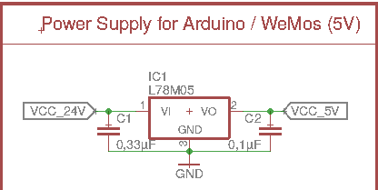
My current idea is to simply use a linear voltage regulator like the L78M05:
Or should I better use a step-down converter (a little more expensive, more parts, harder to route on the PCB) even though the arduino will never, ever use the 3A:
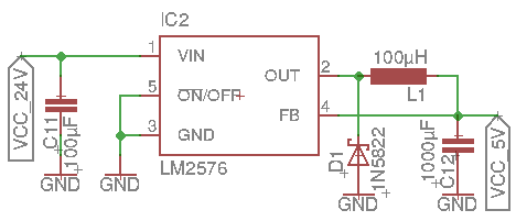
Do you think this will produce a proper power supply for the arduino? I'm afraid to try it out without first getting some second opinions, as this is my first hardware-design project, and I don't want to destroy either my humidifier or the arduino+nrf24...
2) Triggering a Power button press from MySensors
As a button press of the existing hardware buttons simply means connecting to GND, my idea was to use a simple MOSFET transistor (that can handle 24V) parallel to the existing hardware button, i.e.
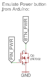
PIN_PWR would be connected to e.g. the D3 pin of the pro mini.Would this work to trigger a Power button press from the arduino?
Would you use this transistor or a different transitor? Or would you even recommend optocouplers to cleaner separate the 5V/3.3V circuit of the arduino from the 24V of the humidifier?
3) Detecting if the Open button was pressed (i.e. the enclosure is open)
As far as I can see, this simply means checking wether the corresponding wire goes to GND. As the internal microcontroller must observe this line, too, I suppose there is some pull-up already in place, so my idea was to simply use a voltage divider from 24V to ~5V to feed the line into the arduino:
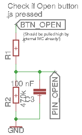
Again, PIN_OPEN is a digital pin (D4) of the arduino.Is using a voltage divider the correct approach here? Or are there better ways to detect BTN_OPEN going from high to GND?
What would be good values for the voltage divider's resistors? I thought of 470k for R2 and 2.2M for R1 (=> 4.22V from 24V).Is there anything I can do to minimize interference with the internal button press detection of the humidifier? No idea, how the internal circuit works and how the PIC16F1933 detects the button press, in particular, I have no idea about existing pull-ups and other components.
4) Detecting which LEDs are on
Strangely, the LEDs are connected to +24V (with a series resistor), so I suppose they are turned on by the internal MC by putting the corresponding pin low.
Does this mean that I can detect a burning led similar to the way I detect the button press? I.e. using a voltage divider and then simply piping into an input pin on the arduino (no pullups needed, obviously):
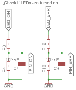
What worries me here is that this basically means I have only the LED, the 10k resistor (on the existing control panel of the humidifier), and the two resistors of the divider in series between +24V and GND, so basically just the LED and a large resistor (10k + ~2-3M). Is this really a good approach?
Any better idea how to detect whether any of the LEDs is on?
What do you think about this project? Are my approaches working at all, and are there better solutions to the issues at hand?
Of couse, I'll make the whole project available on openhardware.io, once I get it working...
Thanks,
Reinhold

