Skip to content
  • MySensors
  • OpenHardware.io
  • Categories
  • Recent
  • Tags
  • Popular
Skins
  • Light
  • Brite
  • Cerulean
  • Cosmo
  • Flatly
  • Journal
  • Litera
  • Lumen
  • Lux
  • Materia
  • Minty
  • Morph
  • Pulse
  • Sandstone
  • Simplex
  • Sketchy
  • Spacelab
  • United
  • Yeti
  • Zephyr
  • Dark
  • Cyborg
  • Darkly
  • Quartz
  • Slate
  • Solar
  • Superhero
  • Vapor

  • Default (No Skin)
  • No Skin
Collapse
Brand Logo
S

sjoerd14

@sjoerd14
About
Posts
7
Topics
2
Shares
0
Groups
0
Followers
0
Following
0

Posts

Recent Best Controversial

  • 💬 Temperature Sensor
    S sjoerd14

    regarding error:

    C:\Users\Admin\Documents\Arduino\libraries\DallasTemperature/DallasTemperature.h:249:13: error: 'int16_t DallasTemperature::millisToWaitForConversion(uint8_t)' is private

    In the latest version of Miles Burton's the function is public and compiling fine.
    https://github.com/milesburton/Arduino-Temperature-Control-Library

    You can import the Lib as zip.
    You have to remove \ archive the lib: ...\libraries\DallasTemperature

    Announcements

  • Deleted device from UI7, now won't add anymore -- RESOLVED
    S sjoerd14

    I had the same problem.
    I deleted the (child) sensors, in order to recreate them with the latest version (2.0)

    When I tried to include them again they where not found.
    I found in the log (http://<vera-ip>/cgi-bin/cmh/log.sh?Device=LuaUPnP) that the devices where still there.
    In ALTUI I found the devices, removed them from there.
    After that I could include the sensors again.

    I am on a new Vera Plus 1.7.2138

    Vera

  • Node error when power via vcc/gnd, OK when using FTDI connection
    S sjoerd14

    @mfalkvidd, I checked using the multimeter. In diode mode, I have 400 ohm between fdti and vcc. When powered a 0.4v drop.
    So both vcc's are not direct connected.

    Still strange it works OK with the 4.4v on the radio and not with 4.9
    At least we have now an idea what
    It's a deek robot clone.
    https://arduino-board.com/boards/dr-pro-mini

    Troubleshooting

  • Node error when power via vcc/gnd, OK when using FTDI connection
    S sjoerd14

    Hi,

    I planned to use a phone checker 1A b7ut now during testing is connect in both cases using the laptop USB. The "NRF24L01+ Socket Adapter Board" from the shop to connect the radio.
    Last latest test was to add an (extra) 4.7 uF, without any diff.

    I am puzzled about the fact appertly the MYSCONTROLER receives the other messages. Why only an issue with the TX messages?

    I am wondering if vcc from the fdti and the other vcc pins are directly connected on the board?

    Thanks for your help.

    Troubleshooting

  • Node error when power via vcc/gnd, OK when using FTDI connection
    S sjoerd14

    Hi,

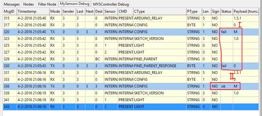
    I have a strange behaviour of the pro-mini (5v)
    When I connect to the VCC and GND on the side rows (next to A3 and D2) then I am not able to cumunicate (to Vera)
    When I connect using the FTDI or a the VCC an GDN of this connecter its working

    I tested it finally using the MYSController see for the first situation I and for second II in the screen print.

    Any one a suggestion what could cause this and/or how to solve this?

    0_1454619006244_Knipsel.JPG

    Troubleshooting

  • Arduino Pro MICRO Pinout for 8 channel Relay
    S sjoerd14

    Hi,

    Here is the example of the code using an 8 delay board.
    I used the Analog devices as much as possible because I intend to include 1-wire temp sensors as well.
    On my (clone) Mini there are 8 analog pins but useable on the bread board because of the location. I will use them in the final perfboard.

      // Example sketch showing how to control physical relays. 
      // This example will remember relay state even after power failure.
      // Using an Array to define the pin's 
    
    #include <MySensor.h>
    #include <SPI.h>
    
    const int RELAY[] = {A0, A1, A2, A3, A4, 6, 7, 8}; // I/O pins for the relays
    #define NUMBER_OF_RELAYS 8 // Total number of attached relays
    #define RELAY_ON 1  // GPIO value to write to turn on attached relay
    #define RELAY_OFF 0 // GPIO value to write to turn off attached relay
    
    MySensor gw;
    
    void setup()  
    {   
      // Initialize library and add callback for incoming messages
      gw.begin(incomingMessage, AUTO, true);
      // Send the sketch version information to the gateway and Controller
      gw.sendSketchInfo("Relay", "1.0");
    
      // Fetch relay status
      for (int sensor=1, pin=0; sensor<=NUMBER_OF_RELAYS;sensor++, pin++) {
        // Register all sensors to gw (they will be created as child devices)
        gw.present(sensor, S_LIGHT);
        // Then set relay pins in output mode
        pinMode(RELAY[pin], OUTPUT);   
        // Set relay to last known state (using eeprom storage) 
        digitalWrite(RELAY[pin], gw.loadState(sensor)?RELAY_ON:RELAY_OFF);
      }
    }
        
    void loop() 
    {
      // Alway process incoming messages whenever possible
      gw.process();
    }
    
    void incomingMessage(const MyMessage &message) {
      // We only expect one type of message from controller. But we better check anyway.
       if (message.type==V_LIGHT) {
         // Change relay state
         digitalWrite(RELAY[message.sensor-1], message.getBool()?RELAY_ON:RELAY_OFF);
         // Store state in eeprom
         gw.saveState(message.sensor, message.getBool());
         // Write some debug info
         Serial.print("Incoming change for sensor:");
         Serial.print(message.sensor);
         Serial.print(", New status: ");
         Serial.println(message.getBool());
       } 
    }
    

    "

    Development pro micro analog pin on p pinout library

  • Boat monitoring using GPRS
    S sjoerd14

    Hi,

    I am considering a setup for monitoring several parameters on my boat:

    • Battery voltage
    • Shore power connection
    • Temp (freezing)
    • Bilge water alarm (level)
    • propane Gas sensor
    • PIR
    • etc

    It should report any abnormalities using SMS/GPRS
    Historic info would be nice, but not 1st prio

    On this site I think I can find all wired/wireless sensors.

    Now I am thinking about the main unit:

    Vera + UMTS router + arduinoGW + Sensors ~ €230-260
    => "plug and play", requires 12 volt, when battery drops not enough power for Vera to send alarm.
    Rpi + Python + UMTS stick + arduinoGW + Sensors ~ €
    => Own python development...
    Rpi + Domoticz + UMTS stick + arduinoGW + Sensors ~ € 100 - 150
    => Is domoticz suitable for this?
    Arduino + GSM shield + arduinoGW + Sensors ~€ 75 - 100
    => Monitoring from sketch to "home" Vera via GPRS?

    Any suggestions or tips? Has anyone already such a setup?

    Thanks in advance
    Sjoerd

    My Project
  • Login

  • Don't have an account? Register

  • Login or register to search.
  • First post
    Last post
0
  • MySensors
  • OpenHardware.io
  • Categories
  • Recent
  • Tags
  • Popular