Navigation

    • Register
    • Login
    • OpenHardware.io
    • Categories
    • Recent
    • Tags
    • Popular
    1. Home
    2. soward
    3. Best
    • Profile
    • Following
    • Followers
    • Topics
    • Posts
    • Best
    • Groups

    Best posts made by soward

    • RE: Why continue to use NRF24L01?

      Mostly power. Check how much power the ESP & wifi use vs NRF & atmel. For non-battery things it's probably not much of an issue though.

      Also the mesh network and repeaters, again less of an issue if you have solid wifi coverage everywhere you would want a sensor.

      There's also a more robust set of libraries and tools for working with various physical sensors on the arduino / atmel side than there is ported to the esp side.

      But if you are just embarking on this now, and none of this items are an issue, there might be some logic in going all ESP/WiFi...

      posted in Hardware
      soward
      soward
    • Battery Powered Emergency Sump

      After a couple of water incursion events, the house was equipped with a battery powered sump pump. Specifically the Basement Watchdog 'Big Dog' model. This device used a large lead acid solid plate ( deep cycle ) battery, a high power 12V water pump, a float valve and a control/charge system. Both the pump and it's float were mounted a few inches above the standard sump pump, and a separate set of discharge pipes was ran which could dump the excess down the hill out in the front yard.

      This system worked well for just short of 10 years, requiring only periodic battery maintenance. Until the control unit failed completely; all LEDs flickering, random beeping sounds. Looking inside the unit I found lots of analog circuitry, and nothing obviously damaged like a bad cap, etc. Battery was good, pump was good, etc. The system cost (not including installation) exceeded $600, so I searched for cheaper options. Basement Watchdog offers several cheaper versions. So I purchased their 'Emergency' version, but retained my existing pump, float and battery. This also worked well for almost 2 years, then its 'battery fail' indicator came on... fair enough, the battery was 12 years old -- though it had probably only cycled 20 times in those 12 years...but sure enough the battery wouldn't hold a charge using an external charger. so I replaced the battery. About 8 months later, another bad battery warning, same deal. And the unit had not been engaged at all over that time. Some reading indicated that the 'Emergency' version had a poorly designed charging circuit, combined with some dodgy wall-wart power supplies, and it was known to kill batteries.

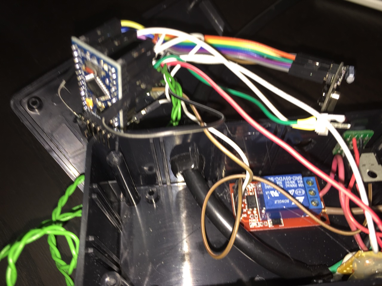
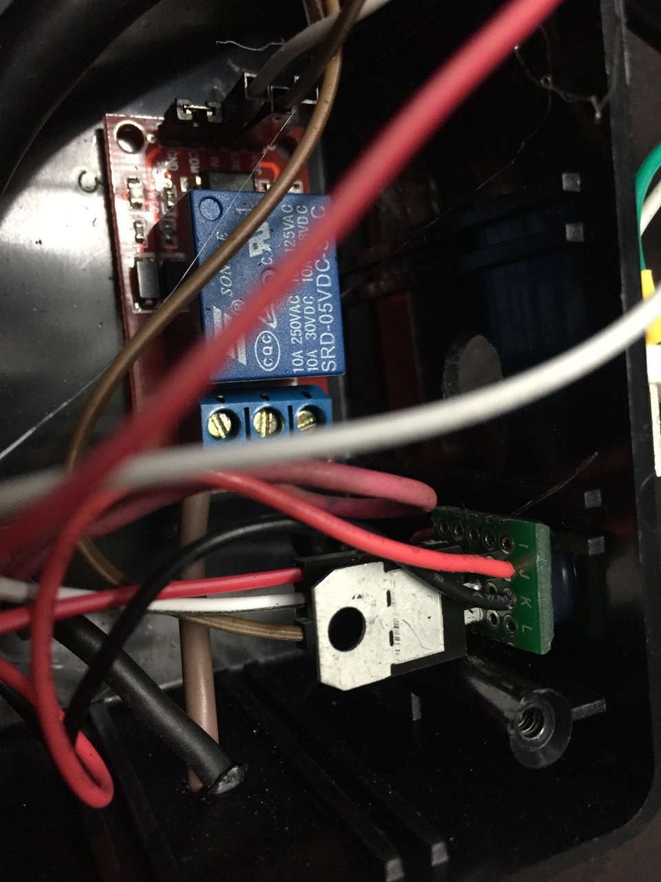
      So I decided to build my own, still keeping the original 12V pump and float. The project is pretty simple. There's a 12V deep cycle battery with a 'intelligent 3Amp charger/conditioner' connected to it's main terminals. From the accessory (screw post) terminals hangs my device. The 12V splits inside there going to a relay and to a simple 7805 linear regulator, which powers a 3.3V 8Mhz Pro Mini. The 5v from the 7805 also powers a single relay board, controlled by the Mini. The float is connected from ground to a pin on the mini, and a push-button switch rescued from an old computer is also connected to allow for manual pump/battery testing. Two LEDs indicate that the system is alive, and if the pump is (or at least should be) activated.

      From the mySensors standpoint, it just appears as a relay/switch. From there I can use the VERA to alert me when the sump is activated, or potentially use other sensors -- such as the floor water sensor I built a long time ago for the DSC Alarm -- to engage the pump. Or run a periodic pump test, etc.

      One thing the BW system had which I'm not sure how to implement was a low-water sensor for the wet cell battery. It was simply a ~5" metal rod which was inserted into one of the cells of the battery via a cap with a tiny hole in it. I'm guessing this was able to produce some amount of micro voltage and when it dropped off past a threshold it meant that it was no longer in contact with enough acid to produce the voltage?

      See below for code and pictures. I should probably diagram the circuit as well...

      most recent sketch:

      // I need two switches for the SUMP. 
      //  1> test switch. Momemtary push engages a ~3-5 second run of the sump pump (and signal back to gateway)
      //  2> Actual float switch from sump pump... Pump should engage when this switch is on, and disenages when it is off.
      //     Very long 'debounce' on the on and off here as the water may have small waves in it...
      // And one relay to connect the 12V battery to the 12V sump motor.
      // And an LED to display some status...
      
      #include <MySensor.h>
      #include <SPI.h>
      #include <Bounce2.h>
      
      #define RELAY  5         // Arduino Digital I/O pin number for relay 
      #define FLOAT  3         // Arduino Digital I/O pin number for button 
      #define TEST_BUTTON 4    // A button to run a sump test.
      #define STATUS_ONLINE 6  // Blinking LED to indicate 'OK/READY!' status
      #define STATUS_ACTIVE 7  // LED to indicate that the pump is (should be) active
      #define CHILD_ID 1       // Id of the sensor child
      
      Bounce floatDebounce = Bounce(); 
      Bounce testDebouncer = Bounce();
      int oldValue=0;
      bool state;
      
      MySensor gw;
      MyMessage msg(CHILD_ID,V_LIGHT);
      
      // Consider making this a MOTION also, and float trigger will trip the zone, so other action can take place?
      // Though how is this really different that monitoring the switch for ON?
      void setup()  
      {  
        Serial.begin(115200);
        
        gw.begin( incomingMessage );
      
        gw.sendSketchInfo("BackupSump", "1.2");
      
       // Setup the float
        pinMode(FLOAT,INPUT);
        // Activate internal pull-up
        digitalWrite(FLOAT,HIGH);
        
        // After setting up the float, setup debouncer
        floatDebounce.attach(FLOAT);
        floatDebounce.interval(750);
        
        // Do the same for the test button, but with a bit more sensativity
        pinMode(TEST_BUTTON, INPUT);
        digitalWrite(TEST_BUTTON,HIGH);
        testDebouncer.attach(TEST_BUTTON);
        testDebouncer.interval(40);
      
        // Register mySensors with gateway
        gw.present(CHILD_ID, S_LIGHT);
      
        pinMode(STATUS_ONLINE, OUTPUT);
      
        pinMode(STATUS_ACTIVE, OUTPUT);
        digitalWrite(STATUS_ACTIVE,false);  
        
        // Sump off on boot
        digitalWrite(RELAY, false);
        // Then set relay pins in output mode
        pinMode(RELAY, OUTPUT);   
             
        Serial.println("Initialized. Awaiting change");
      }
      
      void loop() 
      {
        gw.process();
        
        // 'Breathing' online LED indicator, most of the equation from : http://sean.voisen.org/blog/2011/10/breathing-led-with-arduino/
        float val = (exp(sin(millis()/2000.0*PI)) - 0.36787944)*(108.0 * .75);
        analogWrite(STATUS_ONLINE,val);
        
        // Check on the test button
        if (testDebouncer.update()) {
          if (!testDebouncer.read()) { // Test Button pushed, gateway need not know.
            pump_test();
          }
        }
        
        // Check on our float
        if (floatDebounce.update()) {
          int value = floatDebounce.read();
          // 0 == switch grounded (closed), float underwater.
          if (value != oldValue) {
              // Engage pump even if we cannot talk to gateway.
              Serial.print("Switch value is now: ");
              Serial.println(value?"OFF":"ON");
              digitalWrite(RELAY, value?false:true);
              digitalWrite(STATUS_ACTIVE,value?false:true);
              gw.send(msg.set(value?false:true), true); // Send new state and request ack back
          }
          oldValue = value;
        }
      } 
       
      void incomingMessage(const MyMessage &message) {
           
        if (message.type == V_LIGHT ) {
           // Change relay state
           state = message.getBool();
           digitalWrite(RELAY, state?true:false);
           digitalWrite(STATUS_ACTIVE,state?true:false);     
         } 
      }
      
      // Run the pump for about 5 seconds
      void pump_test() {
        Serial.println("Pump test Engaged.");
        gw.send(msg.set(true), true); // Send new state and request ack back
      
        digitalWrite(STATUS_ONLINE,false);
        digitalWrite(RELAY,true);
        digitalWrite(STATUS_ACTIVE,true);
        
        delay(5000);
        
        digitalWrite(RELAY,false);
        digitalWrite(STATUS_ACTIVE,false);
        
        gw.send(msg.set(false), true); // Send new state and request ack back
        Serial.println("Pump test complete.");
      }
      

      Pics --

      Unit in case and connected to battery, pump, and float (temporary location)
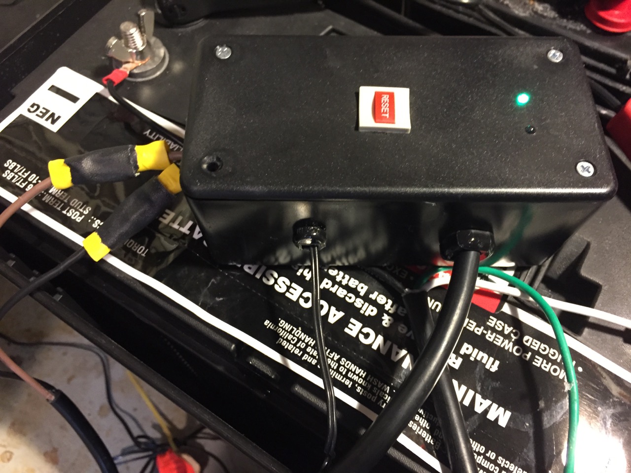
      IMG_2711.jpg
      Case open, parts hanging out:
      IMG_2710.jpg
      Close up of regulator and relay:
      IMG_2706.jpg

      posted in My Project
      soward
      soward
    • RE: ESP8266 WiFi gateway port for MySensors

      I'd been using the ESP gateway for several weeks, but recently was having trouble adding a new sensor I am developing.

      Since the copy of dev I built it with was now out of date, I went ahead and updated... still wasn't working right so while I had the serial link to it I checked and noticed it was crashing and cycling. It would work for hours, until I fired up my new node, then crash about immediately. A few dozen debug(PSTR())'s later, I found a cause.

      In core/MySensorsCore.cpp the result of _msg.getConfig() is dereferenced in a comparison, and it's possible it could return NULL ( like when it's a new node ). I put a check around that and it's not crashing anymore. Which is more than what I can say for my new sensor node....

      I have not tested this change with an AVR.

      I submitted PR 264.

      posted in Development
      soward
      soward
    • 5 Channel (RGBWW) LED Dimmer With Rotary Encoder

      Using a RGBW LED strip, I put over & under cabinet lights in the kitchen, but I wanted some more direct white light right over the stove, so I added an additional white strip there. I also wanted to be able to control it manually, so I tied in a rotary encoder with push-button switch.

      All 5 (RGBWW) are controllable as separate dimmable lights via mySensors + VERA as usual. The final W tied to the encoder can have it's illumination increased/decreased by a turn of the knob, and updates mySensors/VERA on change. Pushing the button will turn off the strip completely if it is on, and restore it to the last known brightness value if it is off.

      Presently it is still on a breadboard while I find the time to master Kicad, or decide that will never happen and solder it together on a perfboard. I am using an external 12V CC supply feeding both a pro mini and 5 MOSFETs to drive the LED strips. It has been running for about 7 months now -- since the breadboard sits on the back top of the cabinets, it provides a low incentive to reconfigure the hardware.

      Most recent sketch:

      /***
       * This program is free software; you can redistribute it and/or
       * modify it under the terms of the GNU General Public License
       * version 2 as published by the Free Software Foundation.
       * 
       * DESCRIPTION
       * This sketch provides 4 channels of Dimmable LED Lights using PWM for the MySensors.org project
       * Inspired by the PWM example sketcy by <henrik.ekblad@gmail.com> and Bruce Lacey.
       * 
       * REVISION HISTORY
       * Version 0.1 - Sept 5, 2014 John Soward <soward@soward.net>  -- Initial implementation based on example scripts.
       * Version 0.2 - Sept 7, 2014 --  <soward@soward.net> -- Adjust Timer resolution, neaten up, separate debugging output 
       * Version 0.3 - July 5, 2015 --  <soward@soward.net> Pin changes, use Bounce2, update encoder state when brightness changed via mySensors net
       *
       ***/
      #define DEBUG 0
      #define SN "RGBWW DIM + ENC"
      #define SV "0.3"
      
      #include <Encoder.h>    // Using https://www.pjrc.com/teensy/arduino_libraries/Encoder.zip
      #include <Bounce2.h>     
      #include <MySensor.h> 
      #include <SPI.h>
      
      // Ardunio pro mini's have PWM only on 3,5,6,9,10,11
      // See http://arduino.cc/en/Main/ArduinoBoardProMini
      #define RED 3      // Arduino pin attached to MOSFET Gate pin
      #define GREEN 5
      #define BLUE 6
      #define WHT 9
      #define WHT2 10    //WHT2 is a pure white strip, distinct from the RGBW strip for over stove use
      
      // Rotary Encoder connections 
      // Better response if one or both of the encoder triggers is on an interrupt pin
      #define ENC_SWITCH 8
      #define ENC_A 2
      #define ENC_B A2
      #define ENC_SCALE 2.56   // scaling encoder 256 steps to 100%
      
      #define FADE_DELAY 5  // Delay in ms
      #define FADE_DELAY_FACTOR 16
      
      // MySenor uses pin 9 for CE by default, , can be changed here.
      // Pin 10 used for CS can also be changed.
      MySensor gw(4,7);
      
      Encoder myEnc(ENC_A, ENC_B);
      Bounce PowerButton = Bounce();
      
      static int levels[5];  // Current dim levels...
      MyMessage dimMsgs[5];
      MyMessage lightMsgs[5];
      int rotValue = 0;   // encoder position (for WHT2)
      int lastBrightness; // last 'on' brightness (for WHT2)
      
      void setup()  
      { 
        //Increase Timer frequency to prevent flicker in Pins 5,6 PWM
        // This alters the performance of millis(), micros() & delay() (basically by 1/16) Unless wiring.c is modified.
        // See http://playground.arduino.cc/Main/TimerPWMCheatsheet
        // W/O this change, a low frequency 'beat' or flicker was exhibited when PWM'ing Pin 5 or 6 and another other pin (on Pro Mini 8Mhz clone)
        TCCR0A = _BV(COM0A1) | _BV(COM0B1) | _BV(WGM00);  
        
        pinMode(RED,OUTPUT);
        pinMode(GREEN,OUTPUT);
        pinMode(BLUE,OUTPUT);
        pinMode(WHT,OUTPUT);
        pinMode(WHT2,OUTPUT);
        
        pinMode(ENC_SWITCH,INPUT);
        digitalWrite(ENC_SWITCH,HIGH);
        PowerButton.attach(ENC_SWITCH);
        PowerButton.interval(80);
      
        // FIXME Mnemonics for the colors/names/locations of the lights could be useful here.
        for (int i = 0; i < 5; i++) {
          dimMsgs[i] = MyMessage(i,V_DIMMER);
          lightMsgs[i] = MyMessage(i,V_LIGHT);
          levels[i] = 20;
        }
      
        startupDance();
        analogWrite(WHT2,0);
      
      #ifdef DEBUG
        Serial.println( SN ); 
      #endif
        gw.begin( incomingMessage );
        
        // Register each color LED Dimmable Light with the gateway
        gw.present( 0, S_DIMMER );
        gw.present( 1, S_DIMMER );
        gw.present( 2, S_DIMMER );
        gw.present( 3, S_DIMMER );
        gw.present( 4, S_DIMMER );
        
        gw.sendSketchInfo(SN, SV);
        // Pull the gateway's current dim level - restore light level upon sendor node power-up
        gw.request( 0, V_DIMMER );
        gw.request( 1, V_DIMMER );
        gw.request( 2, V_DIMMER );
        gw.request( 3, V_DIMMER );
        gw.request( 4, V_DIMMER );
      }
      
      void loop() 
      {
        
        // Encoder and button handling.
        // In this implemenation the Encoder and button control the 2nd White strip, position 4 in the array of strips)
        // The encoder will brighten/dim the strip from it's current value.
        // The button will turn off the strip if it is on, or return it to it's last known brightness if it is off
        bool needsUpdate = false;
        
        int newRotValue = myEnc.read();
        if (newRotValue != rotValue) { // I guess it really has changed
          Serial.print("Encoder update:");
          Serial.println(newRotValue);
          if (newRotValue > 255 || newRotValue < 0) {
              myEnc.write(rotValue); // Enforce max/min
          } else {
            rotValue = newRotValue;
            needsUpdate = true;
          }   
        }
        
        if (PowerButton.update()) {
          if (!PowerButton.read()) {
            Serial.println("Button pushed");
            Serial.print("lastBrightness: ");Serial.println(lastBrightness);
            Serial.print("rotValue: ");Serial.println(rotValue);
            if (rotValue) { // we are on, need to go off
              lastBrightness = rotValue;
              rotValue = 0;
            } else {
              rotValue = lastBrightness;
            }
            myEnc.write(rotValue);
            needsUpdate = true;    
          }
        }
        
        if (needsUpdate) {
            int normalizedValue = rotValue / ENC_SCALE;
            fadeLEDToLevel(4,normalizedValue,0);
            gw.send(dimMsgs[4].set(normalizedValue));
            gw.send(lightMsgs[4].set(normalizedValue > 0 ? 1 : 0));
        }
        
        // Standard mySensors message processing (no sleep)
        gw.process();
      }
      
      void incomingMessage(const MyMessage &message) {
        if (message.type == V_LIGHT || message.type == V_DIMMER) {
              
          //  Retrieve the power or dim level from the incoming request message
          int requestedLevel = atoi( message.data );
          
          // Adjust incoming level if this is a V_LIGHT variable update [0 == off, 1 == on]
          requestedLevel *= ( message.type == V_LIGHT ? 100 : 1 );
          
          // Clip incoming level to valid range of 0 to 100
          requestedLevel = requestedLevel > 100 ? 100 : requestedLevel;
          requestedLevel = requestedLevel < 0   ? 0   : requestedLevel;
          
      #ifdef DEBUG
          Serial.print( "On child id ");
          Serial.print(message.sensor);
          Serial.print( " Changing level to " );
          Serial.print( requestedLevel );
          Serial.print( ", from " ); 
          Serial.println( levels[message.sensor]);
      #endif
      
          fadeLEDToLevel( message.sensor,requestedLevel,FADE_DELAY*FADE_DELAY_FACTOR );
          
          // Sensor 4 is the strip attached the the encoder, update the encoders value, using the scaling factor
          // FIXME Mnemonics might make this more readable/extensible. 
          if (message.sensor == 4) {
              myEnc.write(requestedLevel*ENC_SCALE);
          }  
          
          // Inform the gateway of the current DimmableLED's SwitchPower1 and LoadLevelStatus value...
          gw.send(lightMsgs[message.sensor].set(levels[message.sensor] > 0 ? 1 : 0));
      
          // hek comment: Is this really nessesary?
          // soward: Probably not, unless there exists some reason why the requested value does not equal
          // the set value 
          gw.send( dimMsgs[message.sensor].set(levels[message.sensor]) );
      
          }
      }
      
      void startupDance() {
        int i,j;
        
      // Bring each color up and down independently
         for (i=0;i<5;i++) {
           fadeLEDToLevel(i,100,1);
           delay(50*FADE_DELAY_FACTOR);
           fadeLEDToLevel(i,0,1);
         }
        
       //Bringing each color up sequentially, then back down to 2
        for (i=0;i<5;i++) {
         fadeLEDToLevel(i,100,1);
        }
        delay(50*FADE_DELAY_FACTOR);
        for (i=0;i<5;i++) {
          fadeLEDToLevel(i,2,1);
        }
      }
      
      // Helper function to map controller pins to names for strips
      int pinForID(int ledID) {
        switch (ledID) {
           case 0: return RED;
           case 1: return GREEN;
           case 2: return BLUE;
           case 3: return WHT;
           case 4: return WHT2;
           return 0; // Default to Red
        }
      }
      
      /***
       *  This method provides a graceful fade up/down effect
       */
      void fadeLEDToLevel( int theLED, int toLevel, int wait ) {
          
        int delta = ( toLevel - levels[theLED] ) < 0 ? -1 : 1;
          
        while ( levels[theLED] != toLevel ) {
          levels[theLED] += delta;
          analogWrite( pinForID(theLED), (int)(levels[theLED] / 100. * 255) );
          delay( wait );
        }
      }
      
      posted in My Project
      soward
      soward
    • RE: Combo entry scene trigger?

      I do pretty much this right now with a Yale 'Real Livinig' z-wave keypad lock. It sends an even when a pin code is entered, an 'incorrect pin' code if an invalid one and a 'correct' pin code with the name of the code when a valid one is entered. I can then make as many scenes as I want using the appropriate trigger. Right now I have a couple of lights come on when I enter mine. I have a special one which opens the roll up garage door, and ones for other people send me an alert, etc.

      I think one could do probably craft something cheaper that didn't do the door unlocking, but making it weatherproof and damage resistant like the Yale might be more of a challenge.

      posted in Hardware
      soward
      soward
    • Visiting Sweden

      I'm visiting Sweden next week. Specifically Göteborg, for macsysadmin.se. Since it seemed like a fair number of readers of the forum here are from (somewhere in) Sweden, I thought I might ask for any recommendations of things to see, things to do / not do, etc.

      And if anyone is in or near center city Göteborg and wanted to meet up at some time and discuss projects, etc. that'd be great too!

      I'll be there from mid-afternoon sunday the 27th thru the following friday.

      thanx!

      posted in General Discussion
      soward
      soward
    • RE: Visiting Sweden

      @mfalkvidd Thanks for all the tips and suggestions. I'm quite familiar with procrastination myself, and am putting the finishing touches on the material for my talk just now.

      I have been told there is some conference-related event every evening and but it's not yet clear if they are strict start-stop things or just drop-in ones. Regardless, the one on wednesday doesn't start until 19:00, so I can be at the Steampunk bar at 18:00. I will PM you my contact info, and if you send me yours I can let you know if there is any last minute change of plans (and visa vera).

      -JpS

      posted in General Discussion
      soward
      soward