Battery Powered Emergency Sump
-
After a couple of water incursion events, the house was equipped with a battery powered sump pump. Specifically the Basement Watchdog 'Big Dog' model. This device used a large lead acid solid plate ( deep cycle ) battery, a high power 12V water pump, a float valve and a control/charge system. Both the pump and it's float were mounted a few inches above the standard sump pump, and a separate set of discharge pipes was ran which could dump the excess down the hill out in the front yard.
This system worked well for just short of 10 years, requiring only periodic battery maintenance. Until the control unit failed completely; all LEDs flickering, random beeping sounds. Looking inside the unit I found lots of analog circuitry, and nothing obviously damaged like a bad cap, etc. Battery was good, pump was good, etc. The system cost (not including installation) exceeded $600, so I searched for cheaper options. Basement Watchdog offers several cheaper versions. So I purchased their 'Emergency' version, but retained my existing pump, float and battery. This also worked well for almost 2 years, then its 'battery fail' indicator came on... fair enough, the battery was 12 years old -- though it had probably only cycled 20 times in those 12 years...but sure enough the battery wouldn't hold a charge using an external charger. so I replaced the battery. About 8 months later, another bad battery warning, same deal. And the unit had not been engaged at all over that time. Some reading indicated that the 'Emergency' version had a poorly designed charging circuit, combined with some dodgy wall-wart power supplies, and it was known to kill batteries.
So I decided to build my own, still keeping the original 12V pump and float. The project is pretty simple. There's a 12V deep cycle battery with a 'intelligent 3Amp charger/conditioner' connected to it's main terminals. From the accessory (screw post) terminals hangs my device. The 12V splits inside there going to a relay and to a simple 7805 linear regulator, which powers a 3.3V 8Mhz Pro Mini. The 5v from the 7805 also powers a single relay board, controlled by the Mini. The float is connected from ground to a pin on the mini, and a push-button switch rescued from an old computer is also connected to allow for manual pump/battery testing. Two LEDs indicate that the system is alive, and if the pump is (or at least should be) activated.
From the mySensors standpoint, it just appears as a relay/switch. From there I can use the VERA to alert me when the sump is activated, or potentially use other sensors -- such as the floor water sensor I built a long time ago for the DSC Alarm -- to engage the pump. Or run a periodic pump test, etc.
One thing the BW system had which I'm not sure how to implement was a low-water sensor for the wet cell battery. It was simply a ~5" metal rod which was inserted into one of the cells of the battery via a cap with a tiny hole in it. I'm guessing this was able to produce some amount of micro voltage and when it dropped off past a threshold it meant that it was no longer in contact with enough acid to produce the voltage?
See below for code and pictures. I should probably diagram the circuit as well...
most recent sketch:
// I need two switches for the SUMP.
//  1> test switch. Momemtary push engages a ~3-5 second run of the sump pump (and signal back to gateway)
//  2> Actual float switch from sump pump... Pump should engage when this switch is on, and disenages when it is off.
//     Very long 'debounce' on the on and off here as the water may have small waves in it...
// And one relay to connect the 12V battery to the 12V sump motor.
// And an LED to display some status...

#include <MySensor.h>
#include <SPI.h>
#include <Bounce2.h>

#define RELAY  5         // Arduino Digital I/O pin number for relay
#define FLOAT  3         // Arduino Digital I/O pin number for button
#define TEST_BUTTON 4    // A button to run a sump test.
#define STATUS_ONLINE 6  // Blinking LED to indicate 'OK/READY!' status
#define STATUS_ACTIVE 7  // LED to indicate that the pump is (should be) active
#define CHILD_ID 1       // Id of the sensor child

Bounce floatDebounce = Bounce();
Bounce testDebouncer = Bounce();
int oldValue=0;
bool state;

MySensor gw;
MyMessage msg(CHILD_ID,V_LIGHT);

// Consider making this a MOTION also, and float trigger will trip the zone, so other action can take place?
// Though how is this really different that monitoring the switch for ON?
void setup()
{
  Serial.begin(115200);

  gw.begin( incomingMessage );

  gw.sendSketchInfo("BackupSump", "1.2");

 // Setup the float
  pinMode(FLOAT,INPUT);
  // Activate internal pull-up
  digitalWrite(FLOAT,HIGH);

  // After setting up the float, setup debouncer
  floatDebounce.attach(FLOAT);
  floatDebounce.interval(750);

  // Do the same for the test button, but with a bit more sensativity
  pinMode(TEST_BUTTON, INPUT);
  digitalWrite(TEST_BUTTON,HIGH);
  testDebouncer.attach(TEST_BUTTON);
  testDebouncer.interval(40);

  // Register mySensors with gateway
  gw.present(CHILD_ID, S_LIGHT);

  pinMode(STATUS_ONLINE, OUTPUT);

  pinMode(STATUS_ACTIVE, OUTPUT);
  digitalWrite(STATUS_ACTIVE,false);

  // Sump off on boot
  digitalWrite(RELAY, false);
  // Then set relay pins in output mode
  pinMode(RELAY, OUTPUT);

  Serial.println("Initialized. Awaiting change");
}

void loop()
{
  gw.process();

  // 'Breathing' online LED indicator, most of the equation from : http://sean.voisen.org/blog/2011/10/breathing-led-with-arduino/
  float val = (exp(sin(millis()/2000.0*PI)) - 0.36787944)*(108.0 * .75);
  analogWrite(STATUS_ONLINE,val);

  // Check on the test button
  if (testDebouncer.update()) {
    if (!testDebouncer.read()) { // Test Button pushed, gateway need not know.
      pump_test();
    }
  }

  // Check on our float
  if (floatDebounce.update()) {
    int value = floatDebounce.read();
    // 0 == switch grounded (closed), float underwater.
    if (value != oldValue) {
        // Engage pump even if we cannot talk to gateway.
        Serial.print("Switch value is now: ");
        Serial.println(value?"OFF":"ON");
        digitalWrite(RELAY, value?false:true);
        digitalWrite(STATUS_ACTIVE,value?false:true);
        gw.send(msg.set(value?false:true), true); // Send new state and request ack back
    }
    oldValue = value;
  }
}

void incomingMessage(const MyMessage &message) {

  if (message.type == V_LIGHT ) {
     // Change relay state
     state = message.getBool();
     digitalWrite(RELAY, state?true:false);
     digitalWrite(STATUS_ACTIVE,state?true:false);
   }
}

// Run the pump for about 5 seconds
void pump_test() {
  Serial.println("Pump test Engaged.");
  gw.send(msg.set(true), true); // Send new state and request ack back

  digitalWrite(STATUS_ONLINE,false);
  digitalWrite(RELAY,true);
  digitalWrite(STATUS_ACTIVE,true);

  delay(5000);

  digitalWrite(RELAY,false);
  digitalWrite(STATUS_ACTIVE,false);

  gw.send(msg.set(false), true); // Send new state and request ack back
  Serial.println("Pump test complete.");
}
Pics --
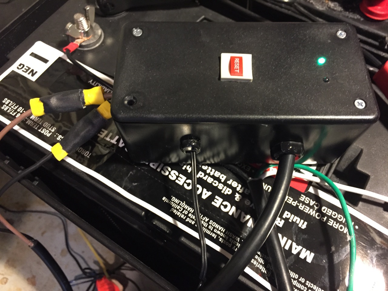
Unit in case and connected to battery, pump, and float (temporary location)
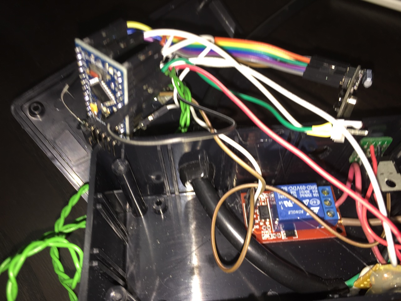
Case open, parts hanging out:
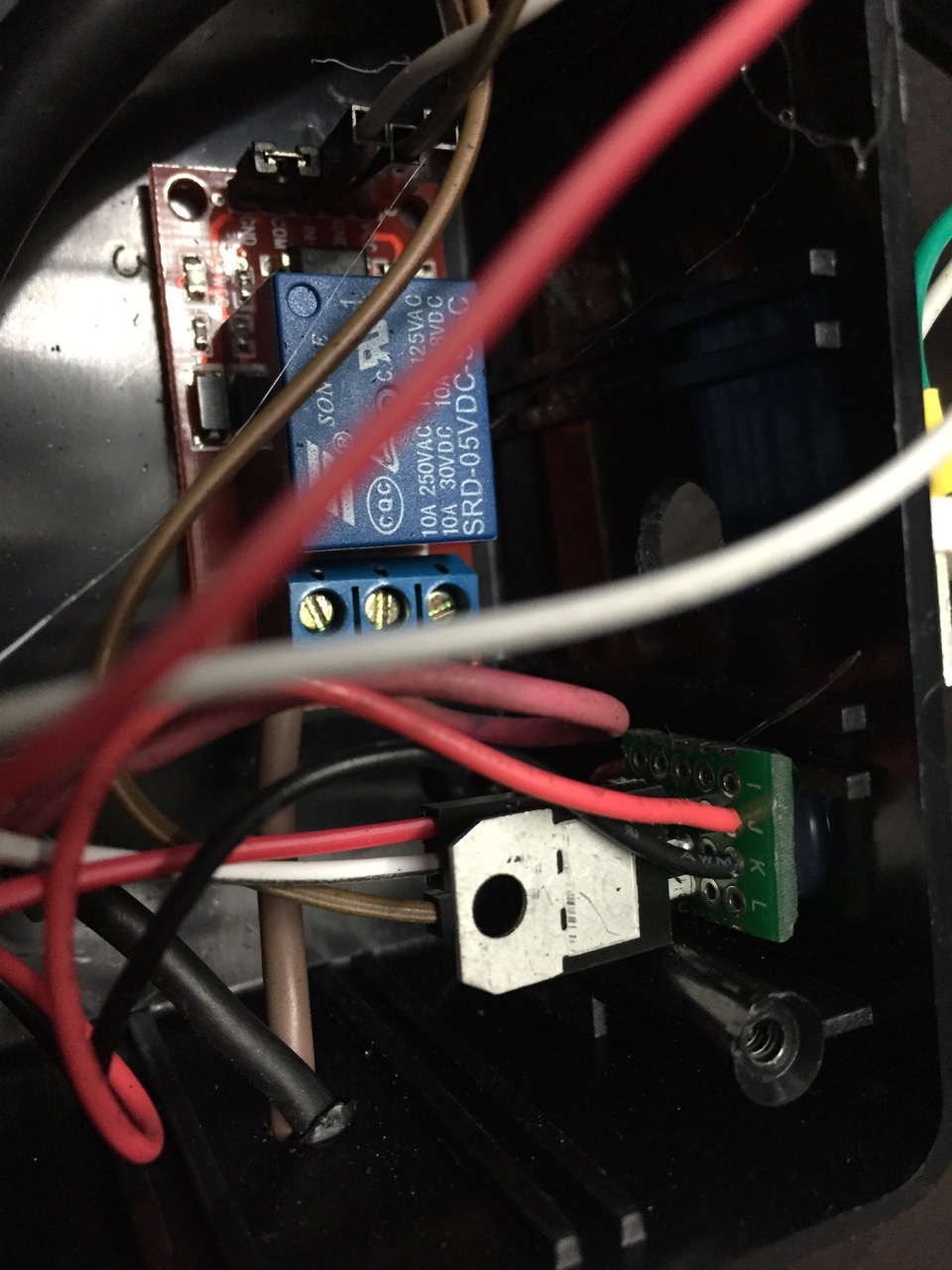
Close up of regulator and relay:
-
After a couple of water incursion events, the house was equipped with a battery powered sump pump. Specifically the Basement Watchdog 'Big Dog' model. This device used a large lead acid solid plate ( deep cycle ) battery, a high power 12V water pump, a float valve and a control/charge system. Both the pump and it's float were mounted a few inches above the standard sump pump, and a separate set of discharge pipes was ran which could dump the excess down the hill out in the front yard.
This system worked well for just short of 10 years, requiring only periodic battery maintenance. Until the control unit failed completely; all LEDs flickering, random beeping sounds. Looking inside the unit I found lots of analog circuitry, and nothing obviously damaged like a bad cap, etc. Battery was good, pump was good, etc. The system cost (not including installation) exceeded $600, so I searched for cheaper options. Basement Watchdog offers several cheaper versions. So I purchased their 'Emergency' version, but retained my existing pump, float and battery. This also worked well for almost 2 years, then its 'battery fail' indicator came on... fair enough, the battery was 12 years old -- though it had probably only cycled 20 times in those 12 years...but sure enough the battery wouldn't hold a charge using an external charger. so I replaced the battery. About 8 months later, another bad battery warning, same deal. And the unit had not been engaged at all over that time. Some reading indicated that the 'Emergency' version had a poorly designed charging circuit, combined with some dodgy wall-wart power supplies, and it was known to kill batteries.
So I decided to build my own, still keeping the original 12V pump and float. The project is pretty simple. There's a 12V deep cycle battery with a 'intelligent 3Amp charger/conditioner' connected to it's main terminals. From the accessory (screw post) terminals hangs my device. The 12V splits inside there going to a relay and to a simple 7805 linear regulator, which powers a 3.3V 8Mhz Pro Mini. The 5v from the 7805 also powers a single relay board, controlled by the Mini. The float is connected from ground to a pin on the mini, and a push-button switch rescued from an old computer is also connected to allow for manual pump/battery testing. Two LEDs indicate that the system is alive, and if the pump is (or at least should be) activated.
From the mySensors standpoint, it just appears as a relay/switch. From there I can use the VERA to alert me when the sump is activated, or potentially use other sensors -- such as the floor water sensor I built a long time ago for the DSC Alarm -- to engage the pump. Or run a periodic pump test, etc.
One thing the BW system had which I'm not sure how to implement was a low-water sensor for the wet cell battery. It was simply a ~5" metal rod which was inserted into one of the cells of the battery via a cap with a tiny hole in it. I'm guessing this was able to produce some amount of micro voltage and when it dropped off past a threshold it meant that it was no longer in contact with enough acid to produce the voltage?
See below for code and pictures. I should probably diagram the circuit as well...
most recent sketch:
// I need two switches for the SUMP.
//  1> test switch. Momemtary push engages a ~3-5 second run of the sump pump (and signal back to gateway)
//  2> Actual float switch from sump pump... Pump should engage when this switch is on, and disenages when it is off.
//     Very long 'debounce' on the on and off here as the water may have small waves in it...
// And one relay to connect the 12V battery to the 12V sump motor.
// And an LED to display some status...

#include <MySensor.h>
#include <SPI.h>
#include <Bounce2.h>

#define RELAY  5         // Arduino Digital I/O pin number for relay
#define FLOAT  3         // Arduino Digital I/O pin number for button
#define TEST_BUTTON 4    // A button to run a sump test.
#define STATUS_ONLINE 6  // Blinking LED to indicate 'OK/READY!' status
#define STATUS_ACTIVE 7  // LED to indicate that the pump is (should be) active
#define CHILD_ID 1       // Id of the sensor child

Bounce floatDebounce = Bounce();
Bounce testDebouncer = Bounce();
int oldValue=0;
bool state;

MySensor gw;
MyMessage msg(CHILD_ID,V_LIGHT);

// Consider making this a MOTION also, and float trigger will trip the zone, so other action can take place?
// Though how is this really different that monitoring the switch for ON?
void setup()
{
  Serial.begin(115200);

  gw.begin( incomingMessage );

  gw.sendSketchInfo("BackupSump", "1.2");

 // Setup the float
  pinMode(FLOAT,INPUT);
  // Activate internal pull-up
  digitalWrite(FLOAT,HIGH);

  // After setting up the float, setup debouncer
  floatDebounce.attach(FLOAT);
  floatDebounce.interval(750);

  // Do the same for the test button, but with a bit more sensativity
  pinMode(TEST_BUTTON, INPUT);
  digitalWrite(TEST_BUTTON,HIGH);
  testDebouncer.attach(TEST_BUTTON);
  testDebouncer.interval(40);

  // Register mySensors with gateway
  gw.present(CHILD_ID, S_LIGHT);

  pinMode(STATUS_ONLINE, OUTPUT);

  pinMode(STATUS_ACTIVE, OUTPUT);
  digitalWrite(STATUS_ACTIVE,false);

  // Sump off on boot
  digitalWrite(RELAY, false);
  // Then set relay pins in output mode
  pinMode(RELAY, OUTPUT);

  Serial.println("Initialized. Awaiting change");
}

void loop()
{
  gw.process();

  // 'Breathing' online LED indicator, most of the equation from : http://sean.voisen.org/blog/2011/10/breathing-led-with-arduino/
  float val = (exp(sin(millis()/2000.0*PI)) - 0.36787944)*(108.0 * .75);
  analogWrite(STATUS_ONLINE,val);

  // Check on the test button
  if (testDebouncer.update()) {
    if (!testDebouncer.read()) { // Test Button pushed, gateway need not know.
      pump_test();
    }
  }

  // Check on our float
  if (floatDebounce.update()) {
    int value = floatDebounce.read();
    // 0 == switch grounded (closed), float underwater.
    if (value != oldValue) {
        // Engage pump even if we cannot talk to gateway.
        Serial.print("Switch value is now: ");
        Serial.println(value?"OFF":"ON");
        digitalWrite(RELAY, value?false:true);
        digitalWrite(STATUS_ACTIVE,value?false:true);
        gw.send(msg.set(value?false:true), true); // Send new state and request ack back
    }
    oldValue = value;
  }
}

void incomingMessage(const MyMessage &message) {

  if (message.type == V_LIGHT ) {
     // Change relay state
     state = message.getBool();
     digitalWrite(RELAY, state?true:false);
     digitalWrite(STATUS_ACTIVE,state?true:false);
   }
}

// Run the pump for about 5 seconds
void pump_test() {
  Serial.println("Pump test Engaged.");
  gw.send(msg.set(true), true); // Send new state and request ack back

  digitalWrite(STATUS_ONLINE,false);
  digitalWrite(RELAY,true);
  digitalWrite(STATUS_ACTIVE,true);

  delay(5000);

  digitalWrite(RELAY,false);
  digitalWrite(STATUS_ACTIVE,false);

  gw.send(msg.set(false), true); // Send new state and request ack back
  Serial.println("Pump test complete.");
}
Pics --
Unit in case and connected to battery, pump, and float (temporary location)
Case open, parts hanging out:
Close up of regulator and relay:
-
@ServiceXp I'm not sure. I looked around for similar devices almost a year ago, and didn't find any consumer grade chargers or monitors which had such, though there were a few commercial devices for the larger flooded cells which appeared to monitor the fluid level somehow. Some even monitored the specific gravity of the electrolyte, but I'm sure those cost more than several 'basement watchdogs.
I suppose I could try to decode the simpler-looking circuit on the 'emergency' model and try to figure out what it was doing, but I think I've forgotten what little I actually learned in Circuits class back in college.
Hello! It looks like you're interested in this conversation, but you don't have an account yet.
Getting fed up of having to scroll through the same posts each visit? When you register for an account, you'll always come back to exactly where you were before, and choose to be notified of new replies (either via email, or push notification). You'll also be able to save bookmarks and upvote posts to show your appreciation to other community members.
With your input, this post could be even better 💗
Register Login