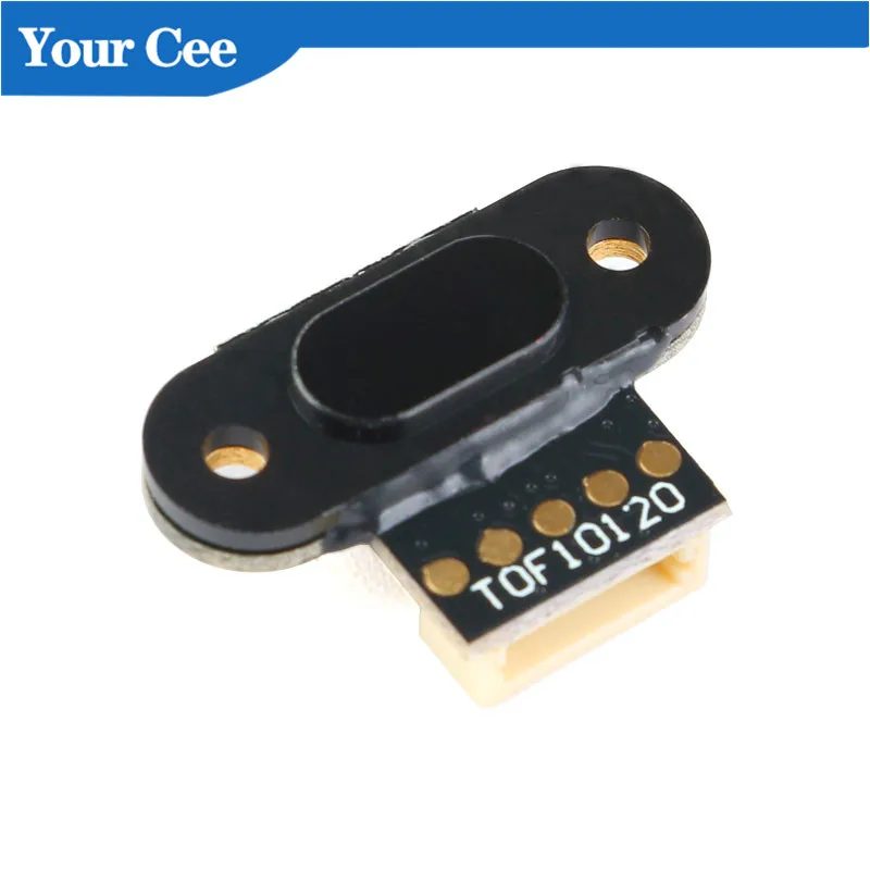
For those interested..
I found another engineer who reverse engineered the JSN-SR04T v2. Not identical, but close. Here's the v2 schematic:
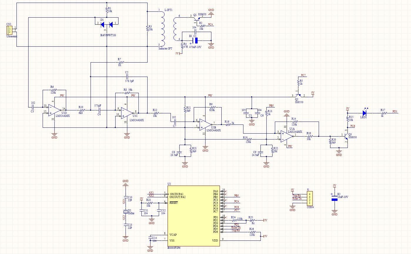
Here's the full theory of operation article he wrote (in Vietnamese, google xlate URL) on how to remove the STM 8 bit microcontroller and do your own echo-pulse based on the waveshape of the detection LED driver.
Here's an interesting tidbit of implementation info that's good to know before you try to use this sensor in a project:
"Defect:
-
JSN-SR04T has a very large opening angle (> = 75 degrees), so it is NOT suitable for measuring distances in tight spaces. Should only be used in open spaces such as outdoors or large-size tanks - no obstructions .
-
If measured in a confined space, the error is very large due to the reflected wave being impacted and the object or the tank - tank wall."
Good to know!... I have seen some of this error in the form of echo width "jitter" both in the bad/unreliable data, as well as with the raw signal combing back on the o-scope:
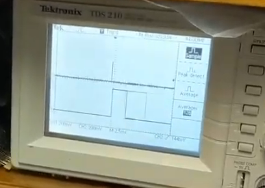
I'll need to experiment with this in confined spaces.. but the JSN units also seems to have problems with "soft targets" (like people in clothes). You can test this yourself by testing with a plywood sheet (the size of a person) vs a clothed person. If anyone finds a way to get more reliable soft target detection, please share here.
These JSN-SR04 modules seem to have multiple operating modes.
On the v2 module, the empty R27 pad controls the echo mode of operation. Here's a best guess regarding the four "operating modes" that I think the author is documenting (attempted to better translate from Vietnamese):
1. Trigger/Echo ECHO-Pulse Mode (default): (R27 open)
You send a 10uS pulse on Trigger pin, then 8 x 40KHz pulses are sent out of sensor, if bounce signal returns within 60mS, the duration of the time to return is sent as pulse-width based on the formula:
Distance = (high time * speed of sound (340M / s)) / 2
2. Continuous Distance-Data TX Mode: (R27=47k)
In this working mode, every 100ms will automatically output the measured sensor distance value, in millimeters. Once the module is powered on, it operates in mode 2 immediately, and data will be sent every 100 ms via echo (TX) pins. The data sent includes: 0xFF + H_DATA + L_DATA + SUM. Breakdown:
- 0xFF: Byte signaling to start sending data.
- H_Data: 8 bits above of the distance.
- L_Data: 8 bits below the distance.
- SUM: Byte checks whether the passed data is correct or not.
- SUM = 0xFF + H_DATA + L_DATA (H+L = 16bits which represents distances in millimeters.) (assume 9600, n, 8, 1 data on echo pin)
For example, the sensor sends FF 07 A1 A7 Sum = A7 = (0x07 + 0xA1 + 0xFF) & 0x00FF. 0x07 is the upper 8 bits of the distance. 0xA1 is the lower 8 bits of the distance. The distance value is 0x07A1, converted to 1953mm in decimal
3 . Standby Distance-Data TX Mode: (R27=120k)
Same as mode2, but module starts in a disabled, standby mode, waiting for a 0x55 command (on trigger pin, as 9600, n, 8, 1), after which module runs same as mode-2 (continuous distance data TX mode)
Well that's all useful info!
Hmm.. No R27 pad on my v3 sensor.. but I wonder what these four jumper pads do :)
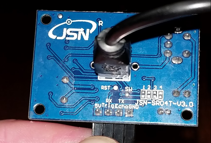
If anyone else gets time to play with these new v3 jumpers.. or figure out how to resolve the "jitter issues", please do share here.
T.Weeks

