I have read this thread, have bought a few E73-2G4M08S1C modules for experimenting, downloaded platformio and tried to flash it. I recognized I am not able to do it with my STM32 link V2 programmer in platformio. Could somebody summarize what are the current options to flash NRF52840? Is there a way how to use STM32 link V2 or we just need to IDE from Arduino to Platformio and invest into new programmer (DK/BMP)?
X
xmonika
@xmonika
Posts
-
Everything nRF52840 -
What did you build today (Pictures) ?@NeverDie a big thank you as I was inspired by many of your post and this was my first Nrf5 project. The backplate is designed in KiCAD and then outsourced for etching to one local semi-hobby service. Modules are then connected via precision header pins (concept inspired by Ardumower)
-
What did you build today (Pictures) ?Have finished RIB king gate opener/controller based on NRF52840 & MySensors.
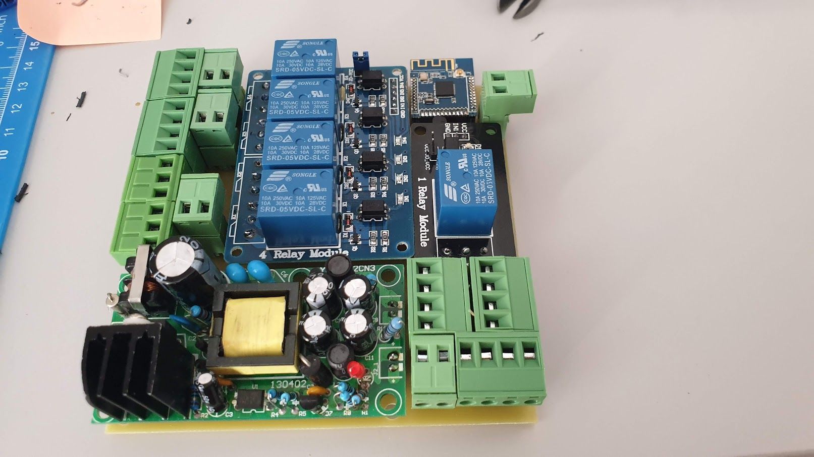 image url)
 -
Which (cheap) bulb in 2020?Prices of bulb went dirty cheap. I have bought bluetooth version https://www.ebay.com/itm/15W-LED-bulb-RGB-bluetooth-APP-control-Dimmable-globe-lamp-for-Google-home-Alexa/254349689226 and thinking of connecting to MySensors (have GW or RPi3 and OpenHab2). In my case I need only white color and some dimming capabilities and I was able to crack down the bluetooth protocol, so I can controll it from raspberry via console (but there will not be direct connection once installed due to longer distance).
There are more than one alternatives how to Mysensorize it:
1/ disassembly bulb and solder out BT module, then replace it for NRF5 modules - problems - the space is very limited, voltage incompatibility, requires another PCB and probably some pasive electronics
2/ run extra bluetooth / Zigbee mesh besides the mysensors and let the Controller talk to each network separatelly
3/ select another bulb where the integration will be easier - which one?
4/ construct extra node which will be bridge between MySensors and bluetoothWhich one is the smartest solution in 2020. I have the same task with several other aplication like BT heating valves.
Thank for your ideas! -
Arduino IDE 1.8.10 - Warning....Still valid in 2020. Got a compilation error "Error resolving FQBN: missing". Downgrade to 1.8.9 helped
-
GUIDE - NRF5 / NRF51 / NRF52 for beginners@omemanti @mfalkvidd Thank you, I think I did it. It works now - or I hope so from the code.
** Programming Finished **
** Verify Started **
nrf51.cpu: target state: halted
target halted due to breakpoint, current mode: Thread
xPSR: 0x61000000 pc: 0x2000002e msp: 0x20004000
verified 1412 bytes in 0.038633s (35.692 KiB/s)
** Verified OK **
** Resetting Target **
shutdown command invoked
What I was confused is that there is erase sketch, but to make it erased there is this trick with burn bootloader. Still the port is greyed out, but it seems I am able to flash blank sketch. Thanks
-
💬 Multi-Sensor: Temp/Humidity/PIR/ Leak/Magnet/Light/Accel-
I've downloaded the source files and tried to compile them.
I got fatal error: sketch/MyBoardNRF5.h: No such file or directory -
Then I renamed MyNRF5Board.h to MyBoardNRF5.h
I got #error No forward link or gateway feature activated. This means nowhere to send messages! Pretty pointless. -
Then I added #define MY_GATEWAY_SERIAL into the code
I got many errors i.e. 'PIN_AIN0' was not declared in this scope
How to compile the downloaded source files?
-
-
GUIDE - NRF5 / NRF51 / NRF52 for beginnersI am starting to experiment with NRF51822. Thank you all for this thread. I am stuck with setting up IDE on Win10 and my MCU is not communicating. What is the correct setup for Arduino IDE?
I have Port still grayed out and error: The selected port not exist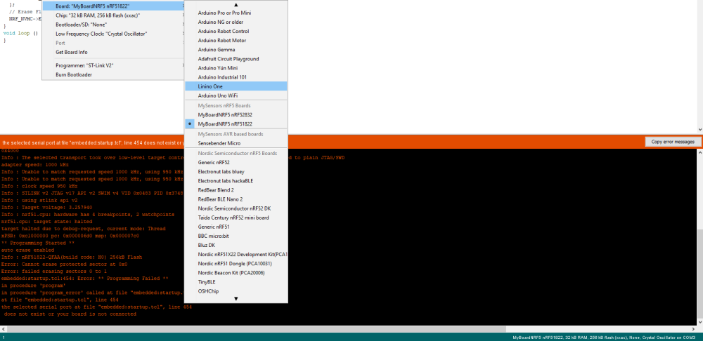
Could that be related to drivers? I've run Zadig, there are more options and I've tried all four of them
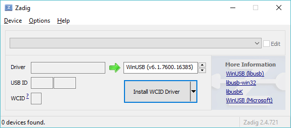
I am not able to upload even erase sketch. Any suggestion where to focus (IDE/Zadig/other)?
-
Can't connect to radio on raspPi with latest stable 2.1.1 build, but works with 2.2.beta but with beta mqtt gateway very unstable...Same by me - combination of Rapberry 3 + mosquitto + OpenHab2. 2.1.1. doesn't start at all (TSM:INIT:TSP FAIL), 2.2.0 beta starts without troubles but after a few minutes the communication is lost (!TSF:MSG:LEN,0!=32). Have capacitors on the node and gateway.
-
Serial GW on RaspberryPI 3 doesn't startIn my case the problem is related to MQTT gateway, so not sure if that helps.
-
Serial GW on RaspberryPI 3 doesn't startTry to install version 2.2.0 beta, this helped me and it is described in other post. The gateway still may be unstable but not only I don't know why 2.1.1 doesn't work.
-
Can't connect to radio on raspPi with latest stable 2.1.1 build, but works with 2.2.beta but with beta mqtt gateway very unstable...I am experiencing the same behavior. 2.1.1. radio is not detected. 2.2.0 beta detected ok.
-
Beginner - what is wrongThe programmer has 10 pins but the GND is presented 4x. Check the picture [here](http://www.avrfreaks.net/forum/adapter-program-10-pin-6-pin-socket-cable-computer-pc-led-reset-power for wiring, this is how I did it.
-
Beginner - what is wrongI just have this problem with "programming" solved. I bought this USBISP programmer, downloaded libUSBk drivers from here and pushed it into SBmicro via programmer USBasp. I don't know why but from some reason two UART programmers were not working.
It may save frustration and time to somebody in future.
-
Beginner - what is wrongUnfortunately I didn't solved it, I just gave it up and am waiting for new ISP programmer to arrive. That is the last piece I didn't changed (I have changed computer/SW, sensebender Micro and it didn't helped). Hope you will be more successfull.
-
Beginner - what is wrongCould be but the same I get on my second computer (win 10 as well). Will experiment with that.
-
Beginner - what is wrongSo I tried Arduino nano (may be clone). The result is simillar - not in sync. But then I tried the nano via standard mini USB cable and also not in sync. Possibly WIN 10 related? I tried it with admin privileges.
-
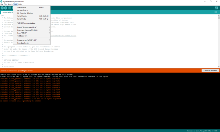
Beginner - what is wrongI have selected 8 MHz. This is what it looks like by me
This is what I did today - got another sensebender micro (SBM) board, soldered jumpers, connected again. Then I measured the conductivity between DTR pin on CP2102 chip and capacitor on DTR wire on SBM. It shall be conected via my wires and it was correctly connected.
Then I run the compillation again and the result is the same - not in sync. So I feel I have replaced everything but still getting the same error.
-
Beginner - what is wrong@tbowmo Yes, second icon from the left (or Ctrl+U).
By pressing Project Upload via programmer (in menu Project or Ctrl+Shift+U) the result is little bit different - no stk500_getsync() attempt 7 of 10: not in sync: resp=0xdb error just uncommented Upload error. -
Beginner - what is wrongSo I have tried it on the different computer and the results are the same.
This is what I did:
- download ide 1.8 here https://www.arduino.cc/en/main/software & install
- download CP CP2102 win 10 drivers here https://www.silabs.com/products/development-tools/software/usb-to-uart-bridge-vcp-drivers
- install mysensors libraries in IDE via manage library internal tool
- add https://raw.githubusercontent.com/mysensors/ArduinoBoards/master/package_mysensors.org_index.json to IDE
- select Sensebender micro board, COM6 (the only available), Programmer AVRISP.mkII
- add necessary libraries to compile the sensebender micro sketch as described here https://www.mysensors.org/about/arduino#optional---install-external-mysensors-examples - via creating zip files and add zip library file to sketch. Necessary libraries were SI7021 + sha204 + RunningAverage
- compile and upload the basic sketch from here https://www.openhardware.io/view/1/Sensebender-Micro
Result is: stk500_getsync() attempt 7 of 10: not in sync: resp=0xdb