Part time standalone sensor + parallel control of nodes
-
Hi all!
I'm planning my home automation in a way I can still control the things locally if the mysensors stuff somehow does not work (radio interference, gateway down, controller down, repeater's nodes down, etc). For example, in my house, all light actuators will respond to a clap pattern, plus the activation through the controller, and I will also keep the existing normal light switches, in parallel with the sensor (I know how to do that using a 3 way switch and a 3 way relay). So if anything goes wrong with the comms, I can still use a clap pattern. And if the circuit goes down entirely, I can still use the normal switch.
I call it wife-safe system ;-) It means my wife will not complain when the automation has a problem because the good old way will still work.I'm looking for help in mainly two points:
1-My wife will probably be using mostly the normal switches, so how can I "sense" when the light is turned on through the normal wall switch so the node can inform the gateway and then pass this status to the controller? Light sensors are not an option because natural window light will fool the controller. I heard something about using current sensors, but have no idea about them. If you guys can post some links mainly to how they work and where can I buy them, it will help me a lot. Feel free to suggest other ways too!2-Is there any disadvantage (other than the controller not be updated with the current status of sensors) of allowing a sensor to act standalone, even when the controller is not reachable?
Will it keep trying to update all the time generating generating any kind of radio traffic? Once the gateway turns on (in the event it was off by some incident), will the node be able to detect it and then send the updated current status of that sensor? -
@marcusvdt said:
and I will also keep the existing normal light switches, in parallel with the sensor (
In my opinion, not as easy or straightforward a goal as you may like. Converting your wall switch from a primary controlling device to one that only participates in the control of your device is a challenge. Look to create a wireless actuator (wall mounted) that will send a signal to the gateway that instructs the sensor node to toggle the device.
@marcusvdt said:
2-Is there any disadvantage (other than the controller not be updated with the current status of sensors) of allowing a sensor to act standalone, even when the controller is not reachable?
actually a big advantage. Programing to allow a local switch (or your clapper example) to function even if the controller is daydreaming is a real marriage saver, particularly when you first launch your MySensors network and are still figuring out how to make it reliable (which will happen, but not on the first day!!!).
You did take the correct first step, and that is coming to the forum where a heck of a lot of talent seems to collect (pun intended).
-
Just to add my two cents --- Since begin of this year, I've installed relays and dimmer (all mySensor based) to controll the lights in my house.
I rewire each original wall switch to reach the GND and a Input Pin on arduino, and the sketch I've upload in arduino accept commands from radio as well as from original (local) switch.
Everything is working flawless , I never had to replace any module or re-work anything. Even if the controller (I have Vera) gets offline, the wall switch still commanding the arduino (and thus the ligths controlled by it).
And everything survived to the raining season here (Brazil is the country with more lightning storms I think), it is very common end up with burned fixed phones / TVs / etc after a heavy tropical storm. Also the power eventually goes up&down more than once during every storm. mySensors braved resisted to all of this, never gave up!
Just an experience to share.
@rvendrame Nice experience!
Can you share a photo of your module?
With details where you put it and how you've wired it to fit tight spaces... I'm thinking about similiar solution... :-) -
@rvendrame I'm from Brazil too!
Will keep the conversation in English so others can participate too.I've considered rewiring the switch so it goes to the arduino and I believe it is the better option to keep the circuit simple and to make sure the arduino will always be updated with the status of the light.
The problem with it, is if the arduino board goes dead, there is no alternative to control the lights. In my case, I'm using switching power supplies (220v AC to 5v DC) bought from dx.com to power my circuits and since I've never used these specific supplies before, I don't know if they are likely to live for a long time, or are likely to burn if powered for a long time.
The alternative I'm going for, is to use the relays themselves as parallel light switches. Preety easy to achieve because the 3 outputs of the relays can be wired in parallel with my current light switches just as a normal wall parallel light switch would be. The challenge in this case is to tell the arduino the light has been turned on by the normal wall switch. To solve this, I've read somewhere about using AC current sensors, so the circuit can sense when there is AC current passing through, and hence detecting if the lights are on or off.
Just don't want to over complicate the circuit if the AC current sensor is not needed. I'm actually looking for simpler ideas... -
As I mentioned I've running for 6 months without any glitch. I used old 5V phone-charges (very cheap ones), and didn't have any problem so far. I will post some photos as soon as I find them (as currently I don't want to disassemble the wall boxes).
But our Brazilian "4x2" box is big enough to fit the arduino, radio, power supply and the regular switch (and nothing else, said). Make sure you isolated everything very well.
-
As I mentioned I've running for 6 months without any glitch. I used old 5V phone-charges (very cheap ones), and didn't have any problem so far. I will post some photos as soon as I find them (as currently I don't want to disassemble the wall boxes).
But our Brazilian "4x2" box is big enough to fit the arduino, radio, power supply and the regular switch (and nothing else, said). Make sure you isolated everything very well.
@rvendrame said:
As I mentioned I've running for 6 months without any glitch. I used old 5V phone-charges (very cheap ones), and didn't have any problem so far. I will post some photos as soon as I find them (as currently I don't want to disassemble the wall boxes).
But our Brazilian "4x2" box is big enough to fit the arduino, radio, power supply and the regular switch (and nothing else, said). Make sure you isolated everything very well.
yes, curious to see how you sense change at the mains power switch and have the arduino sense that. Brazil is 220 volt, yes?
-
I have re-wired the original switch to go to Arduino (it shorts GND and a digital input). So the original switch does not control the lamp directly anymore (only arduino does, via mysensors and local switch).
Yes 220v, the phone charges are okay as they usually accept AC between 100 to 240v. -
Here is a quick example of the setup.
The Switch is connected to GND and a digital input on Arduino. Activate the internal pull-up on the digital input and sample the pin in order to detect the position of the switch. The Arduino sketch can then treat the switch as a 3-way switch and toggle the light (relay) when switch state changes.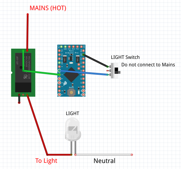
-
Hi all!
I'm planning my home automation in a way I can still control the things locally if the mysensors stuff somehow does not work (radio interference, gateway down, controller down, repeater's nodes down, etc). For example, in my house, all light actuators will respond to a clap pattern, plus the activation through the controller, and I will also keep the existing normal light switches, in parallel with the sensor (I know how to do that using a 3 way switch and a 3 way relay). So if anything goes wrong with the comms, I can still use a clap pattern. And if the circuit goes down entirely, I can still use the normal switch.
I call it wife-safe system ;-) It means my wife will not complain when the automation has a problem because the good old way will still work.I'm looking for help in mainly two points:
1-My wife will probably be using mostly the normal switches, so how can I "sense" when the light is turned on through the normal wall switch so the node can inform the gateway and then pass this status to the controller? Light sensors are not an option because natural window light will fool the controller. I heard something about using current sensors, but have no idea about them. If you guys can post some links mainly to how they work and where can I buy them, it will help me a lot. Feel free to suggest other ways too!2-Is there any disadvantage (other than the controller not be updated with the current status of sensors) of allowing a sensor to act standalone, even when the controller is not reachable?
Will it keep trying to update all the time generating generating any kind of radio traffic? Once the gateway turns on (in the event it was off by some incident), will the node be able to detect it and then send the updated current status of that sensor?@marcusvdt said:
My wife will probably be using mostly the normal switches, so how can I "sense" when the light is turned on through the normal wall switch...
@Cory said:
Here is a quick example of the setup.
doesn't seem to meet the requirement of the OP.
-
As I mentioned I've running for 6 months without any glitch. I used old 5V phone-charges (very cheap ones), and didn't have any problem so far. I will post some photos as soon as I find them (as currently I don't want to disassemble the wall boxes).
But our Brazilian "4x2" box is big enough to fit the arduino, radio, power supply and the regular switch (and nothing else, said). Make sure you isolated everything very well.
@rvendrame said:
As I mentioned I've running for 6 months without any glitch. I used old 5V phone-charges (very cheap ones), and didn't have any problem so far. I will post some photos as soon as I find them (as currently I don't want to disassemble the wall boxes).
But our Brazilian "4x2" box is big enough to fit the arduino, radio, power supply and the regular switch (and nothing else, said). Make sure you isolated everything very well.
@rvendrame
Did you used some kind of box to isolate the circuit inside the 4x2 wall enclosure? My goal is to do exactly that, but my circuit is a little bigger now because of the sound sensor module (for the claps) plus the power supply which certainly is bigger than yours.Regarding the normal wall switch, I think I will need to do either as you said, or maybe using a momentary switch (like the ones used for bell) to allow for the same wall switch to be used either to program a new clap pattern or to switch the light on/off (I would control it on the sketch, depending on the time the momentary switch got pressed. Long press=program mode ; quick press = turn light on/off).
Did you made something different for normal light switches that you already had a 3 way wall switch in parallel with another 3 way switch?
@Cory thanks! This is exactly the schematic that I considered using but was not too happy about it, because I wanted to be able to control the lights if the circuit goes down. However @rvendrame told us he is having a good experience with this, then I think I'm going for that.
@BulldogLowell the solution proposed allow control with the normal switches, but it still depends on the circuit to be perfectly working. So it partially achieves my requirement because my wife will scream only if the circuit is dead, which seems unlikely to happen.
Even being more inclined now for doing it the way @Cory and @rvendrame said, I'm still interested in finding some information about how the AC current sensor would fit my needs (mostly about the size and additional components that would be required if using it that way,)
Thanks everybody,
-
@marcusvdt said:
Did you used some kind of box to isolate the circuit inside the 4x2 wall enclosure? My goal is to do exactly that, but my circuit is a little bigger now because of the sound sensor module (for the claps) plus the power supply which certainly is bigger than yours.
Here in my country the wall-boxes are generally made by plastic (placed in brick walls).
I also kept the original power suply box (in fact it is more a plug than a box), I only removed the two pins from it, and ran the wires from inside out. Everything fitted perfected.
Please note that in many countries this is not legally acceptable --- Only certified stuff can be put inside the wall box! (and it should only be worked by certified electricians ;-) )
Regarding the normal wall switch, I think I will need to do either as you said, or maybe using a momentary switch (like the ones used for bell) to allow for the same wall switch to be used either to program a new clap pattern or to switch the light on/off.
Either a momentary (push button) or regular (on-off) switch will work, it is just a matter of adapt the way arduino will interpret the reads from the input pin.
Did you made something different for normal light switches that you already had a 3 way wall switch in parallel with another 3 way switch?
I didn't install it in any 3 way circuit (will do it soon), but I see two ways:
1- use a 2-pole relay playing the role of one of the switches (and in this case Arduino will not know if the light is on or off)
or maybe better
2- move all the 3 way circuit to the GND & Arduino PIN, so You keep the 3-way behavior, and your controller knows if the light is ON or OFF.Hope it helps...
-
@rvendrame said:
As I mentioned I've running for 6 months without any glitch. I used old 5V phone-charges (very cheap ones), and didn't have any problem so far. I will post some photos as soon as I find them (as currently I don't want to disassemble the wall boxes).
But our Brazilian "4x2" box is big enough to fit the arduino, radio, power supply and the regular switch (and nothing else, said). Make sure you isolated everything very well.
@rvendrame
Did you used some kind of box to isolate the circuit inside the 4x2 wall enclosure? My goal is to do exactly that, but my circuit is a little bigger now because of the sound sensor module (for the claps) plus the power supply which certainly is bigger than yours.Regarding the normal wall switch, I think I will need to do either as you said, or maybe using a momentary switch (like the ones used for bell) to allow for the same wall switch to be used either to program a new clap pattern or to switch the light on/off (I would control it on the sketch, depending on the time the momentary switch got pressed. Long press=program mode ; quick press = turn light on/off).
Did you made something different for normal light switches that you already had a 3 way wall switch in parallel with another 3 way switch?
@Cory thanks! This is exactly the schematic that I considered using but was not too happy about it, because I wanted to be able to control the lights if the circuit goes down. However @rvendrame told us he is having a good experience with this, then I think I'm going for that.
@BulldogLowell the solution proposed allow control with the normal switches, but it still depends on the circuit to be perfectly working. So it partially achieves my requirement because my wife will scream only if the circuit is dead, which seems unlikely to happen.
Even being more inclined now for doing it the way @Cory and @rvendrame said, I'm still interested in finding some information about how the AC current sensor would fit my needs (mostly about the size and additional components that would be required if using it that way,)
Thanks everybody,
@marcusvdt said:
I'm still interested in finding some information about how the AC current sensor would fit my needs (mostly about the size and additional components that would be required if using it that way,)
You can get current sensing modules on eBay relatively cheap. Just go to eBay and search for "Arduino current sensor". You'll see a number of options that are designed for different amperages and some will slide over your existing wiring and others will need to be connected with screw terminals. The output of those will connect to an analog input on the Arduino.
There are also split core current transformers that you can clamp over wires without having to undo them. Here's an example: http://www.crmagnetics.com/Assets/ProductPDFs/CR3100.pdf. They'll need some additional (burden) resistors in order to use them with an Arduino. Be careful with them though, as without the resistors, the voltage on them can go very high (in the kv range).
Cheers
Al -
Just to add my two cents --- Since begin of this year, I've installed relays and dimmer (all mySensor based) to controll the lights in my house.
I rewire each original wall switch to reach the GND and a Input Pin on arduino, and the sketch I've upload in arduino accept commands from radio as well as from original (local) switch.
Everything is working flawless , I never had to replace any module or re-work anything. Even if the controller (I have Vera) gets offline, the wall switch still commanding the arduino (and thus the ligths controlled by it).
And everything survived to the raining season here (Brazil is the country with more lightning storms I think), it is very common end up with burned fixed phones / TVs / etc after a heavy tropical storm. Also the power eventually goes up&down more than once during every storm. mySensors braved resisted to all of this, never gave up!
Just an experience to share.
@rvendrame What power supply do you use for your nodes? This is a kind of show me because I did not find a safe, cheap and tiny power supply I can install in the wall. And relays consume to much client to power them with batteries...
-
I used some similar (or same) as this one (I removed the pins):
For my further modules, I found something that looks like a more "professional" solution (not sure if really is):
http://www.dx.com/p/switching-power-supply-board-module-green-5v-600ma-151578#.VVeCTWDOmtA
But I didn't install those "in production" yet, As my new nodes still 'under development' . The PSUs at least provided the said 5V, so no issues for now ;-)
-
Ok, that is the only affordable solution I found, too. I am still searching for a cheap encapsulated power supply which fits behind the mains switch (together with arduino, relay and nrf24 :D) Those power supplys do exist, but are too expensive for buying one for every light switch in the house.
Did you add some kind of fuse to your installaion? Do you mind sharing some pictures of the hardware?
-
I took some pictures but I need to look for them. Now the modules are installed and I don't want to touch everything.
No I don't have a fuse in the wall box, only at the main panel (a circuit breaker for every wire in the house).
Note that this is not allowed in many countries. Here in Brazil the walls are generally brick-maden , within plastic boxes for switches / outlets. So in general it is not too dangerous if a device like that fire up.
The the 'single' wall box here have 10 x 7 x 7 cm "usable" space. It is tight, but somehow possible to accommodate the phone charger + arduino + radio + triac or relay + original switch + original wires (and some air). ;-)
The double box is aprox. 10 x 14 x 7cm , much better for it.
.
-
Here in Germany the wall boxes are round and have a diameter of about 6 cm and a depth of about 4-6 cm. Compared to that your 10x7x7 box is huge. :) I think I would have to dsign a custom Arduino pcb. Still waiting for someone to do this job.
Hello! It looks like you're interested in this conversation, but you don't have an account yet.
Getting fed up of having to scroll through the same posts each visit? When you register for an account, you'll always come back to exactly where you were before, and choose to be notified of new replies (either via email, or push notification). You'll also be able to save bookmarks and upvote posts to show your appreciation to other community members.
With your input, this post could be even better 💗
Register Login