Motion Sensor Recycled based on minimalistic PCB arduino design
-
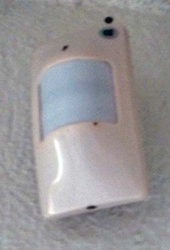
Take an old motion sensor:
Remove existing PCB:
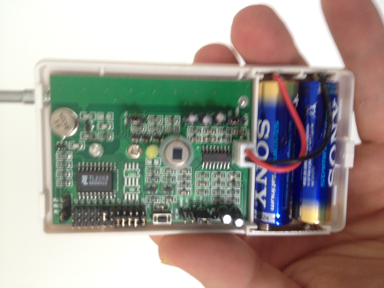
Insert mysensors technology:

With more skills, it would look nicer:
Sketch:
#include <SPI.h>
#include <MySensor.h>


unsigned long SLEEP_TIME = 7200000; // Sleep time between reports (in milliseconds)
unsigned long SLEEP_TIME_AFTER_MOTION = 30000; // Forced Sleep after motion report


#define DIGITAL_INPUT_SENSOR 3   // The digital input you attached your motion sensor.  (Only 2 and 3 generates interrupt!)
#define INTERRUPT DIGITAL_INPUT_SENSOR-2 // Usually the interrupt = pin -2 (on uno/nano anyway)
#define CHILD_ID 1   // Id of the sensor child

boolean interrupted = false;
int batteryRound = 0;

#define BATTERY_ROUNDS 20


MySensor gw;
// Initialize motion message
MyMessage msg(CHILD_ID, V_TRIPPED);


void setup()
{
  //switchClock(1<<CLKPS2);
  delay(1000);

  gw.begin();

  // Send the sketch version information to the gateway and Controller
  gw.sendSketchInfo("Motion Sensor VC Int", "1.2");

  pinMode(DIGITAL_INPUT_SENSOR, INPUT);      // sets the motion sensor digital pin as input
  // Register all sensors to gw (they will be created as child devices)
  gw.present(CHILD_ID, S_MOTION);


  gw.sleep(1000);

}

void loop()
{


  // Read digital motion value
  boolean tripped = digitalRead(DIGITAL_INPUT_SENSOR) == HIGH;
  gw.send(msg.set(tripped ? "1" : "0")); // Send tripped value to gw

  batteryRound++;

  if ((interrupted == false) || // wake up from timer?
      (batteryRound >= BATTERY_ROUNDS) )
  {
    batteryRound = 0;
    // measure battery state
    long sensorValue = readVcc();

    // 100 -> 3000, 0 -> 2000
    if (sensorValue < 2000)
    {
      sensorValue = 0;
    }
    else
    {
      sensorValue -= 2000;
    }


    int batteryPcnt = (int)((float)(sensorValue) / 10.0);

    if (batteryPcnt > 100) batteryPcnt = 100;

    gw.sleep(1000);

    gw.sendBatteryLevel(batteryPcnt);
  }
  ;


  if (tripped == true) {
    // take a brake and do not report motion for some time
    interrupted = true;  // don't send vcc after short sleep
    gw.sleep(SLEEP_TIME_AFTER_MOTION);
  }
  // Sleep until interrupt comes in on motion sensor
  else interrupted = gw.sleep(INTERRUPT, CHANGE, SLEEP_TIME);

}


// see http://provideyourown.com/2012/secret-arduino-voltmeter-measure-battery-voltage/
long readVcc() {
  // Read 1.1V reference against AVcc
  // set the reference to Vcc and the measurement to the internal 1.1V reference
#if defined(__AVR_ATmega32U4__) || defined(__AVR_ATmega1280__) || defined(__AVR_ATmega2560__)
  ADMUX = _BV(REFS0) | _BV(MUX4) | _BV(MUX3) | _BV(MUX2) | _BV(MUX1);
#elif defined (__AVR_ATtiny24__) || defined(__AVR_ATtiny44__) || defined(__AVR_ATtiny84__)
  ADMUX = _BV(MUX5) | _BV(MUX0);
#elif defined (__AVR_ATtiny25__) || defined(__AVR_ATtiny45__) || defined(__AVR_ATtiny85__)
  ADMUX = _BV(MUX3) | _BV(MUX2);
#else
  ADMUX = _BV(REFS0) | _BV(MUX3) | _BV(MUX2) | _BV(MUX1);
#endif

  delay(2); // Wait for Vref to settle
  ADCSRA |= _BV(ADSC); // Start conversion
  while (bit_is_set(ADCSRA, ADSC)); // measuring

  uint8_t low  = ADCL; // must read ADCL first - it then locks ADCH
  uint8_t high = ADCH; // unlocks both

  long result = (high << 8) | low;

  result = 1125300L / result; // Calculate Vcc (in mV); 1125300 = 1.1*1023*1000
  return result; // Vcc in millivolts
}

void switchClock(unsigned char clk)
{
  cli();

  CLKPR = 1 << CLKPCE; // Set CLKPCE to enable clk switching
  CLKPR = clk;
  sei();
}
Minimalistic PCB (self designed with fritzing):
mysduino2.fzzhttps://oshpark.com/shared_projects/mcUfoUxu
The PCB has a flexible design (use jumpers):
- use with battery (used here)
- use with 5 volt (and LE33 for NRF24L01+)
- use with voltage stabilazitaion to 3.3V (LE33) for ATMEGA328P and NRF24l01+
-
Take an old motion sensor:
Remove existing PCB:
Insert mysensors technology:
With more skills, it would look nicer:
Sketch:
#include <SPI.h>
#include <MySensor.h>


unsigned long SLEEP_TIME = 7200000; // Sleep time between reports (in milliseconds)
unsigned long SLEEP_TIME_AFTER_MOTION = 30000; // Forced Sleep after motion report


#define DIGITAL_INPUT_SENSOR 3   // The digital input you attached your motion sensor.  (Only 2 and 3 generates interrupt!)
#define INTERRUPT DIGITAL_INPUT_SENSOR-2 // Usually the interrupt = pin -2 (on uno/nano anyway)
#define CHILD_ID 1   // Id of the sensor child

boolean interrupted = false;
int batteryRound = 0;

#define BATTERY_ROUNDS 20


MySensor gw;
// Initialize motion message
MyMessage msg(CHILD_ID, V_TRIPPED);


void setup()
{
  //switchClock(1<<CLKPS2);
  delay(1000);

  gw.begin();

  // Send the sketch version information to the gateway and Controller
  gw.sendSketchInfo("Motion Sensor VC Int", "1.2");

  pinMode(DIGITAL_INPUT_SENSOR, INPUT);      // sets the motion sensor digital pin as input
  // Register all sensors to gw (they will be created as child devices)
  gw.present(CHILD_ID, S_MOTION);


  gw.sleep(1000);

}

void loop()
{


  // Read digital motion value
  boolean tripped = digitalRead(DIGITAL_INPUT_SENSOR) == HIGH;
  gw.send(msg.set(tripped ? "1" : "0")); // Send tripped value to gw

  batteryRound++;

  if ((interrupted == false) || // wake up from timer?
      (batteryRound >= BATTERY_ROUNDS) )
  {
    batteryRound = 0;
    // measure battery state
    long sensorValue = readVcc();

    // 100 -> 3000, 0 -> 2000
    if (sensorValue < 2000)
    {
      sensorValue = 0;
    }
    else
    {
      sensorValue -= 2000;
    }


    int batteryPcnt = (int)((float)(sensorValue) / 10.0);

    if (batteryPcnt > 100) batteryPcnt = 100;

    gw.sleep(1000);

    gw.sendBatteryLevel(batteryPcnt);
  }
  ;


  if (tripped == true) {
    // take a brake and do not report motion for some time
    interrupted = true;  // don't send vcc after short sleep
    gw.sleep(SLEEP_TIME_AFTER_MOTION);
  }
  // Sleep until interrupt comes in on motion sensor
  else interrupted = gw.sleep(INTERRUPT, CHANGE, SLEEP_TIME);

}


// see http://provideyourown.com/2012/secret-arduino-voltmeter-measure-battery-voltage/
long readVcc() {
  // Read 1.1V reference against AVcc
  // set the reference to Vcc and the measurement to the internal 1.1V reference
#if defined(__AVR_ATmega32U4__) || defined(__AVR_ATmega1280__) || defined(__AVR_ATmega2560__)
  ADMUX = _BV(REFS0) | _BV(MUX4) | _BV(MUX3) | _BV(MUX2) | _BV(MUX1);
#elif defined (__AVR_ATtiny24__) || defined(__AVR_ATtiny44__) || defined(__AVR_ATtiny84__)
  ADMUX = _BV(MUX5) | _BV(MUX0);
#elif defined (__AVR_ATtiny25__) || defined(__AVR_ATtiny45__) || defined(__AVR_ATtiny85__)
  ADMUX = _BV(MUX3) | _BV(MUX2);
#else
  ADMUX = _BV(REFS0) | _BV(MUX3) | _BV(MUX2) | _BV(MUX1);
#endif

  delay(2); // Wait for Vref to settle
  ADCSRA |= _BV(ADSC); // Start conversion
  while (bit_is_set(ADCSRA, ADSC)); // measuring

  uint8_t low  = ADCL; // must read ADCL first - it then locks ADCH
  uint8_t high = ADCH; // unlocks both

  long result = (high << 8) | low;

  result = 1125300L / result; // Calculate Vcc (in mV); 1125300 = 1.1*1023*1000
  return result; // Vcc in millivolts
}

void switchClock(unsigned char clk)
{
  cli();

  CLKPR = 1 << CLKPCE; // Set CLKPCE to enable clk switching
  CLKPR = clk;
  sei();
}
Minimalistic PCB (self designed with fritzing):
mysduino2.fzzhttps://oshpark.com/shared_projects/mcUfoUxu
The PCB has a flexible design (use jumpers):
- use with battery (used here)
- use with 5 volt (and LE33 for NRF24L01+)
- use with voltage stabilazitaion to 3.3V (LE33) for ATMEGA328P and NRF24l01+
@FotoFieber
I am curious why you cut through the existing lens of the old PIR? Could you have used that lens instead for your HC-SR501 and discarded the little dome lens?Nice hack! I have also seen many cheap PIR devices and am in the process of hacking mysensors into a PIR led nightlight but I am trying to cross utilize the existing PIR. Almost there...
-
With the next PIR device I will try to reuse the lens. Attaching the HC-SR501 is more difficult with such a setup.
I just wanted to use a proofen design I use in other setups with my first proof of concept.
-
Nice... I'm about to mod my motion sensor flood lights in a similar manner, but will reuse the lens and also have a relay for the lighting. Then any motion sensor could trigger any number of relay-enabled lights, like if motion is detected by any sensor on the back of the house all lights on the back could power on instead of just the one that detected motion..
-
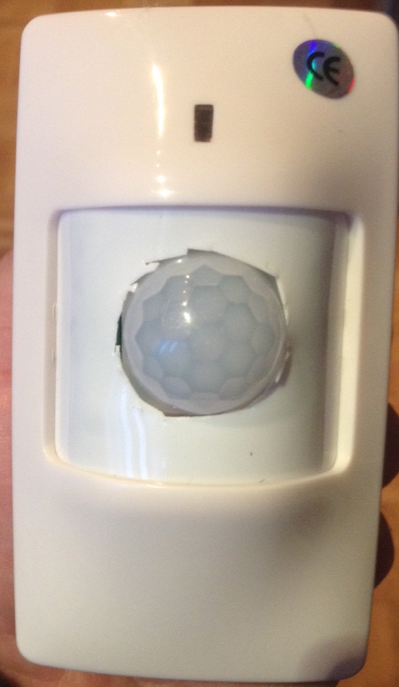
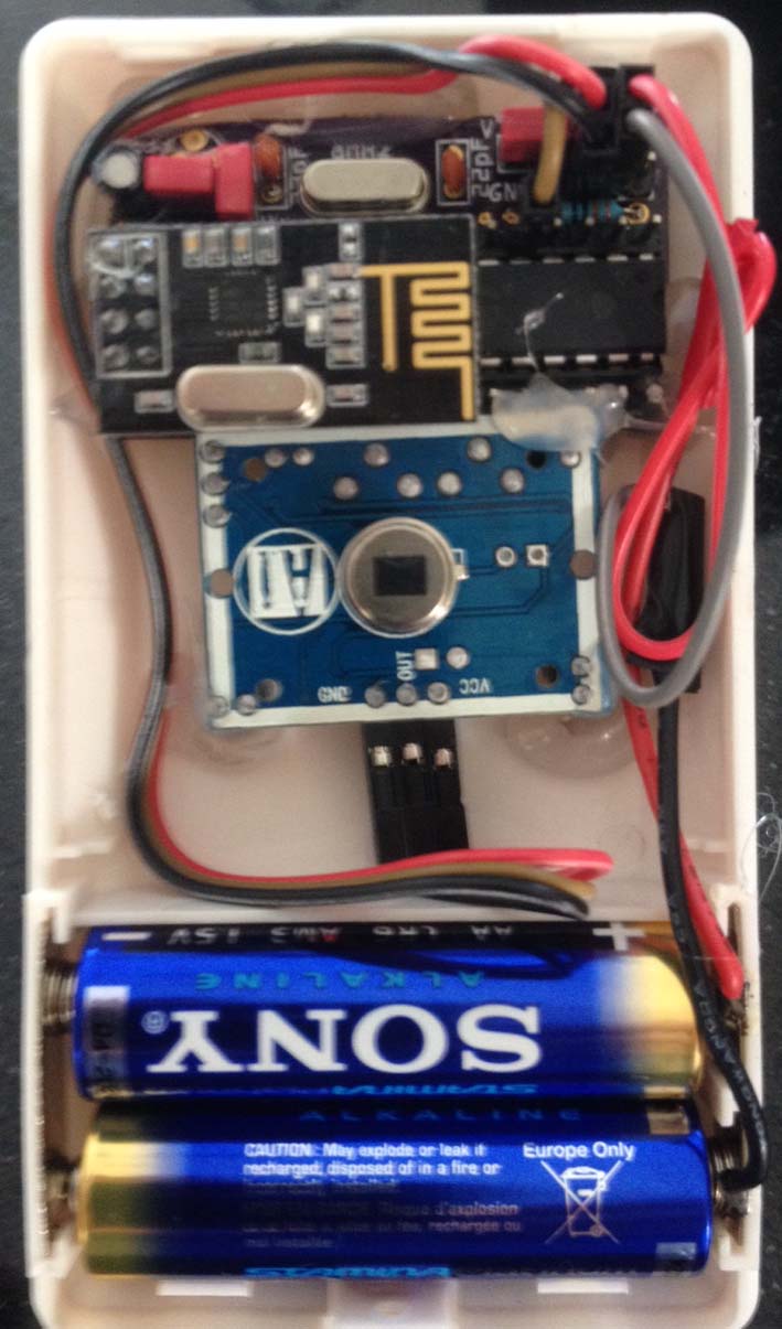
Second design with reusing the lens:
-
Second design with reusing the lens:
Nice and compact! Is that your custom board?
-
Yes, this is a minimalistic NRF Arduion PCB:
http://forum.mysensors.org/topic/595/pcb-boards-for-mysensors/11
Hello! It looks like you're interested in this conversation, but you don't have an account yet.
Getting fed up of having to scroll through the same posts each visit? When you register for an account, you'll always come back to exactly where you were before, and choose to be notified of new replies (either via email, or push notification). You'll also be able to save bookmarks and upvote posts to show your appreciation to other community members.
With your input, this post could be even better 💗
Register Login