Mysensored Doorbell
-
After a long and tedious war with this doorbell (current causalities: two dead arduinos, 1 dead relay and one dead optocoupler) I decided to stop trying to be too smart for my own good and do it in a way I can understand.
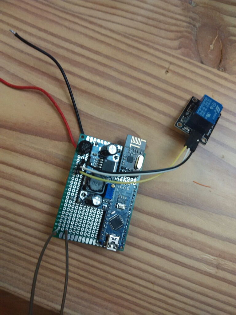
The bell has two circuits. one is 9v ac that comes from a transformer inside the wall. this goes through a rectifier and buck converter into the arduino (yes, I know the buck converter is not needed. However, it works and without it two arduinos died on me). Ringing the doorbell ground pin 3. The sketch then activate the relay that close the original circuit.
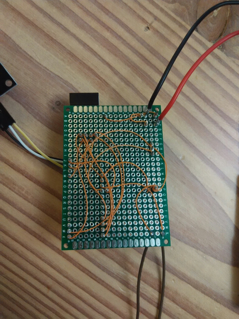
It is almost completely wire wrapped as I had to undo and redo the circuit so many times.
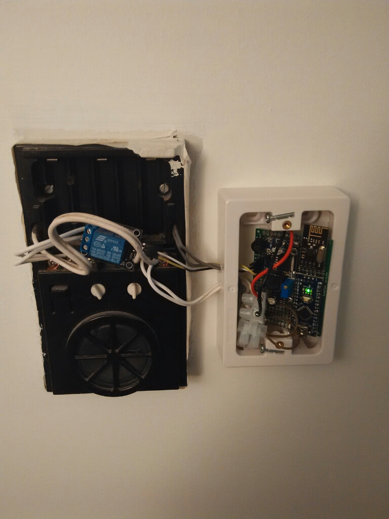
It is hosted inside a standard surface mount power/light switch box with blank plate.
As Marry Poppins said "A thing of beauty is a joy forever!"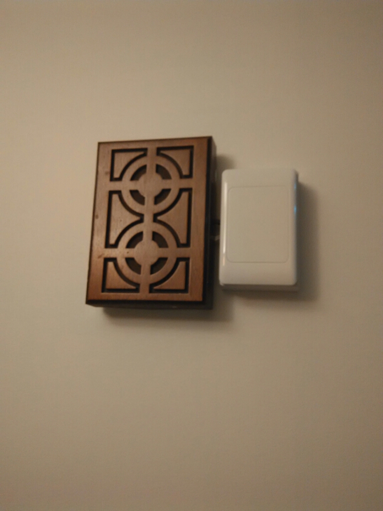
Isn't it nice with everything covered?
Here is the sketch:
// Doorbell sensor
// to ring, ground pin 3. connect the relay that close the original circuit to pin 4
//

#include <MySensor.h>
#include <SPI.h>
#include <Bounce2.h>

#define CHILD_ID 3
#define BUTTON_PIN  3  // Arduino Digital I/O pin for button/reed switch
#define RELAY_PIN  4  // Arduino Digital I/O pin bell relay

MySensor gw;
Bounce debouncer = Bounce();
int oldValue=-1;

// Change to V_LIGHT if you use S_LIGHT in presentation below
MyMessage msg(CHILD_ID,V_TRIPPED);

void setup()
{
  gw.begin();

 // Setup the button
  pinMode(BUTTON_PIN,INPUT);
  pinMode(RELAY_PIN,OUTPUT);
  // Activate internal pull-up
  digitalWrite(BUTTON_PIN,HIGH);

  // After setting up the button, setup debouncer
  debouncer.attach(BUTTON_PIN);
  debouncer.interval(5);

  // Register binary input sensor to gw (they will be created as child devices)
  // You can use S_DOOR, S_MOTION or S_LIGHT here depending on your usage.
  // If S_LIGHT is used, remember to update variable type you send in. See "msg" above.
  gw.present(CHILD_ID, S_DOOR);
}


//  Check if digital input has changed and send in new value
void loop()
{
  debouncer.update();
  // Get the update value
  int value = debouncer.read();

  if (value != oldValue) {
     // Send in the new value
     Serial.println(value);
     gw.send(msg.set(value==HIGH ? 0 : 1));
     if (value == 0) {
     	Serial.println("activating rely for 1 sec");
     	digitalWrite(RELAY_PIN, HIGH);
     	delay(1000);
     	digitalWrite(RELAY_PIN, LOW);
     }
     oldValue = value;
  }
}
Please feel free to comment - I am actually a bit disappointed that I didn't manage to do this the "right way" but it seems that the doorbell circuit is not "real" dc but half rectified AC. This is just a guess - I don't have the equipment to check this . As such it destroys components nicely, especially mechanical relays....
The downside of doing it this way is that the doorbell will not ring if the arduino dies. well, they can always knock, can't they? -
Just an update: this works perfectly. I always know when I miss the postmen now....
-
@Moshe-Livne see the wire wrap would it stay this way or solder. next?
The tool is $20 seems a lot but is it worth it in those?
Plus the wait time.
However cool project.@5546dug Yes, 20$ now looks like a lot of money... Last time I used it it was over a 100$ :-)
Anyway, I also hesitated but a few soldering mistakes and the inability to save your soldered components without a reflow station made me resort back to wire wrap. In retrospect it is probably the best 20$ I spent in this hobby. Reasons:- It is fairly quick - no need to wait for the iron to heat. you want to do something you just do it.
- you can do it anywhere - its almost like knitting.... you can do it while cooking dinner or watching tv (ok, I am making this up) but really - no need for powerpoint of lots instruments
- no obnoxious fumes so the kids can "help"
- unless you are really good at soldering (and I am not) you can't get anything remotely as neat.
- it is very zen like :-)
this is the one i got http://www.aliexpress.com/item/free-shipping-1PCS-305-meters-long-electrical-wire-line-high-quality-30awg-ok-line-Wire-Wrap/32319341509.html
the wire will probably last me a lifetime....properly made wirewrap is as permanent as soldering, at least according to wikipedia. never had problems with wirewrap deteriorating
-
Upvote and love for your wire wrap. It was good enough for space rockets and nuclear power plants so I'm sure your doorbell interconnections will stay safe as well.
-
@Dwalt Including the Apollo 13 one? :-)
I can see why. If anything goes wrong you want to be able to fix it with no electricity and with as little equipment overhead as possible. -
@Dwalt said:
The onboard guidance computers for the Apollo moon missions were all wire wrapped.
Really?? That's madness!
@Moshe Livne - Cmon...use a soldering iron! I bought a couple of these
http://www.hobbyking.com/hobbyking/store/__24789__Soldering_Station_with_Adjustable_Heat_Range_with_AUS_plug.html
They are up to temp in 10secs...
Hello! It looks like you're interested in this conversation, but you don't have an account yet.
Getting fed up of having to scroll through the same posts each visit? When you register for an account, you'll always come back to exactly where you were before, and choose to be notified of new replies (either via email, or push notification). You'll also be able to save bookmarks and upvote posts to show your appreciation to other community members.
With your input, this post could be even better 💗
Register Login