MySensorfying a cheap moodlight
-
It might be just me, but since I discovered my Sensors, I look at the world differently. I want to put MySensors in everything. So last week I came across some cheap mood-lights in a shop. They're 3 euro's a piece. Before I bought them I checked if they can be opened easy and that was the case.
The mood-light is a 3 AAA powered diffused 5mm LED with one resistor. The diffused LED only has to pens and in it is an IC that loops through a mood-light program. But I couldn't use the LED, because in the future I want to control the mood-light as an RGB lamp as well. So I stripped the electronics out of the mood-light to see if there's enough space to put in a Arduino Pro Mini 3.3V and a Antenna. It looked like it would fit.
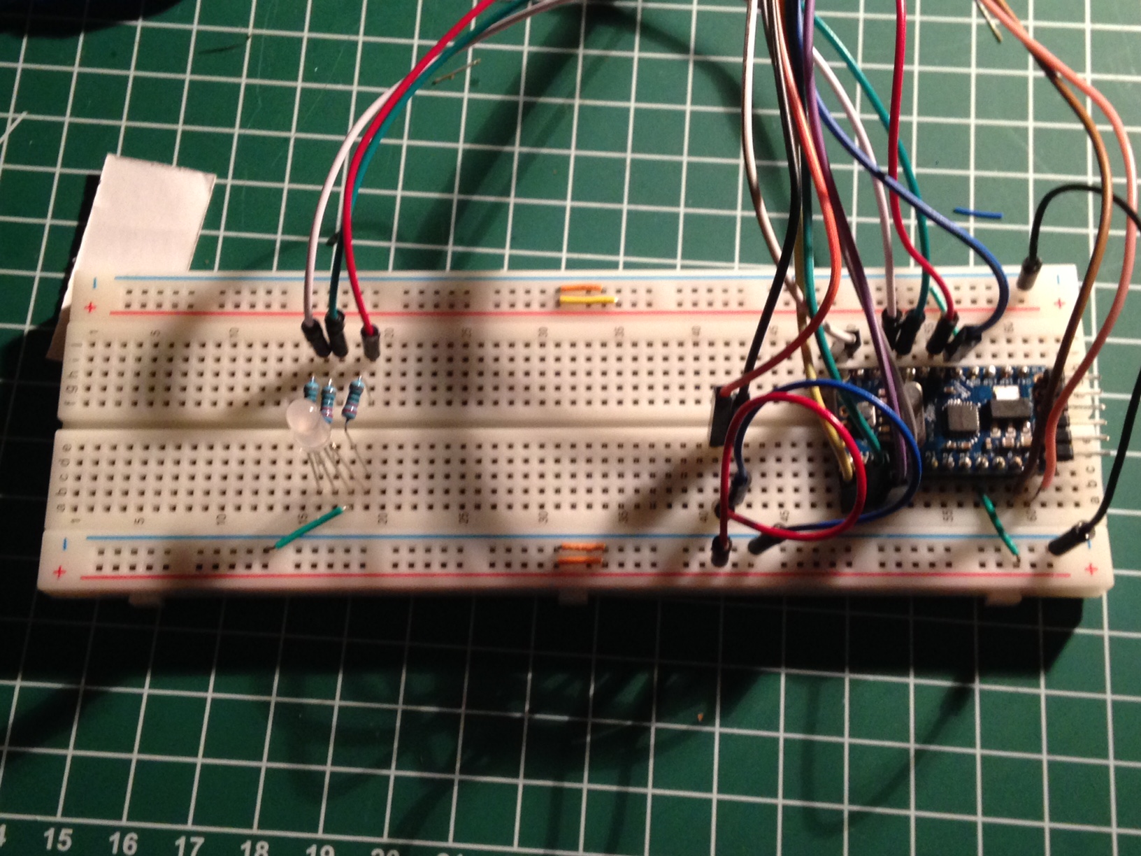
I ordered a couple Pro Mini 3.3V and ordered a couple of diffused 5mm RGB leds. I put everything on a breadboard and developed a sketch.
I had a hard time finding a good Mood-light example. Most of the examples on instructables.com didn't have a smooth transition between the different colors. But luckily I found a good library called MoodLight by Kasper Kamperman. You can download the library from his blog http://www.kasperkamperman.com/blog/arduino-moodlight-library/
The first version implements only a Mood-light. I tried to add the S_RGB but my Domoticz version doesn't support it. So I will put that in the sketch as well. I plan to use that light as a mood-light, but also as warning lamp. E.g. if someone is comming to my front door it will show a green color.
/**
 * MySensors Moodlight
 * Version 1.0
 * created September 22nd 2015
 * by Theo
 *
 * Change log:
 * 27-09-2015 Stable version released after a couple days of testing.
 *
 * Description:
 *   Sketch for creating a cheap MySensors controlled MoodLight which also can be controlled as an dimmable RGB light.
 *
 * Future plans:
 * - enable it as an RGB lamp as well. Have to wait until Domoticz supports it. Which will probably be in the next stable version.
 *
 * Dependencies:
 *   MoodLight.h
 *
 * Hardware used:
 *   Arduino Pro Mini 3.3V
 *   Difused 5mm RGB led
 *   LR2401 Antenna
 *   one 4.7Uf capacitor
 *   three 220 Ohm resistors, to prevent the RGB led from burning out, but might be lower because we're feeding it only 3.3V instead of 5V
 *   A really cheap 3 AAA battery powered moodLight (found it in a store for around 3 euros)
 *
 * Total costs without the regulator circuit (also adapter not included, used an old phone power adapter)
 *   Arduino 6.00 euro
 *   RGB led 0.60 euro
 *   antenna 2.00 euro
 *   4.7 uF  0.30 euro
 *   resistors 0.00 euro had them laying around doing nothing
 *   moodlight housing 3.00 euro
 *   wires and solder etc. 0.00 euro had that laying around ass well
 *
 * Sums up to 11.90 euro add 2 euro to it for wires etc and it's still below 15 euro. Nice!!! ;-)
 */

/**
 * Include libraries.
 */
#include <MoodLight.h>  // great library for moodlight implementations.
#include <SPI.h>        // needed for the Antenna
#include <MySensor.h>   // include the real magic.

/**
 * declare Pins used by the sketch. Use #define because that the compiler will replace it so it saves a bit of memory
 */
#define REDPIN 3              // pwm pin with red led (Only use a PWM that is not being occupied by the antenna)
#define GREENPIN 5            // pwm pin with green led (Only use a PWM that is not being occupied by the antenna)
#define BLUEPIN 6             // pwm pin with blue led (Only use a PWM that is not being occupied by the antenna)
#define MOODLIGHTDELAY 175    // the amount of time a particular moodlight value is being shown before the next one will be shown
#define SATURATION 255        // use value between 0 - 255 <--- This is a candidate to remove
#define BRIGHTNESS 255        // use value between 0 - 255 <--- This is a candidate to remove
#define MLHUEUPPERLEVEL 359   // The higher bound of the ml's hue factor
#define SN "Moodlight"        // Define the Sketch's name
#define SV "1.0"              // Define the sketch's version
#define CHILD_ID_MOODLIGHT 0  // Define the child ID of the moodlight

/**
 * Declare new data types, enum etc
 */
// Light program modes
enum LIGHTMODE {
  LIGHTOFF = 0,
  MOODLIGHT = 1,
  RGBVALUE = 2   // reserved for future useage
};

/**
 * Declare global variables (haven't looked into what saturation and brightness will do for the moodlight)
 */
int hue = 0; // use value between 0 - 359
MoodLight ml = MoodLight(); // create MoodLight object
int currentLightMode = LIGHTOFF;
long RGB_values[3] = {0,0,0};

MySensor gw;
MyMessage lightMsg( CHILD_ID_MOODLIGHT, V_LIGHT);

/**
 * Initialize Sketch. Declare pins and MySensors etc.
 */
void setup() {
  // Serial.begin( 115200 );
  // Setup PWM pins for output
  pinMode( REDPIN, OUTPUT );
  pinMode( GREENPIN, OUTPUT );
  pinMode( BLUEPIN, OUTPUT );

   // initialize ml for first time display.
   ml.setHSB(hue, SATURATION , BRIGHTNESS );

  // Initialize mySensor gateway
  gw.begin( incomingMessage );
  gw.sendSketchInfo(SN, SV);

  // Register the LED Dimmable Light with the gateway
  gw.present( CHILD_ID_MOODLIGHT, S_LIGHT );
  // It just me being neurotic, but inform controller that power level is 100%
  gw.sendBatteryLevel( 100 );

  // Request the current Moodlight status from the controller.
  gw.request( CHILD_ID_MOODLIGHT, V_LIGHT );
}

/*
 * Calculate red, green, blue values based upon current hue, saturation and brightness.
 * Display the new values and adjust the hue to the next step.
 */
void setAndShowNextMoodlightValue() {
  // assign current values to the ml object
  ml.setHSB( hue, SATURATION, BRIGHTNESS );

  // read the Red, Green and Blue values and assign them to the led pins
  analogWrite( REDPIN, ml.getRed() );
  analogWrite( GREENPIN, ml.getGreen() );
  analogWrite( BLUEPIN, ml.getBlue() );

  hue++; // set the next moodlight step
  if ( hue > MLHUEUPPERLEVEL ) { // adjust if we've reached the upperlevel
    hue = 0;
  }
}

/**
 * Main loop of the Sketch
 */
void loop() {
  if ( currentLightMode == MOODLIGHT ) {
    setAndShowNextMoodlightValue();
  }
  gw.wait( MOODLIGHTDELAY );
}

/**
 * Callback function for handling messages received from the gateway.
 */
void incomingMessage(const MyMessage &message) {
  if ( message.sensor == CHILD_ID_MOODLIGHT && message.type == V_LIGHT ) { // received a Light Status from the gateway
    currentLightMode = message.getBool() == 1 ? MOODLIGHT : LIGHTOFF;
    // adjust the RGB led to the (new) light state
    if ( currentLightMode == MOODLIGHT ) {
      analogWrite( REDPIN, ml.getRed() );
      analogWrite( GREENPIN, ml.getGreen() );
      analogWrite( BLUEPIN, ml.getBlue() );
    }
    else {
      analogWrite( REDPIN, 0 );
      analogWrite( GREENPIN, 0 );
      analogWrite( BLUEPIN, 0 );
    }
  }
}
So after playing with the mood-light on the breadboard for a couple of days. Just to see if it's stable. I finally found some time to solder the Arduino and the Antenna and mount everything in the mood-light.
I cut some dupont cables in half and soldered them directly on the proMini. I was lucky that I had the same colors as used in the connecting the radio article on the mysensor build site. So it'll be very easy to replace the radio when needed. There's also a 4,7 uf cap that I stuck directly in the VCC and ground pins of the dupont cables.
It was really hard to mount the electronics in the light, because you have all most no working space. But I managed to do it.
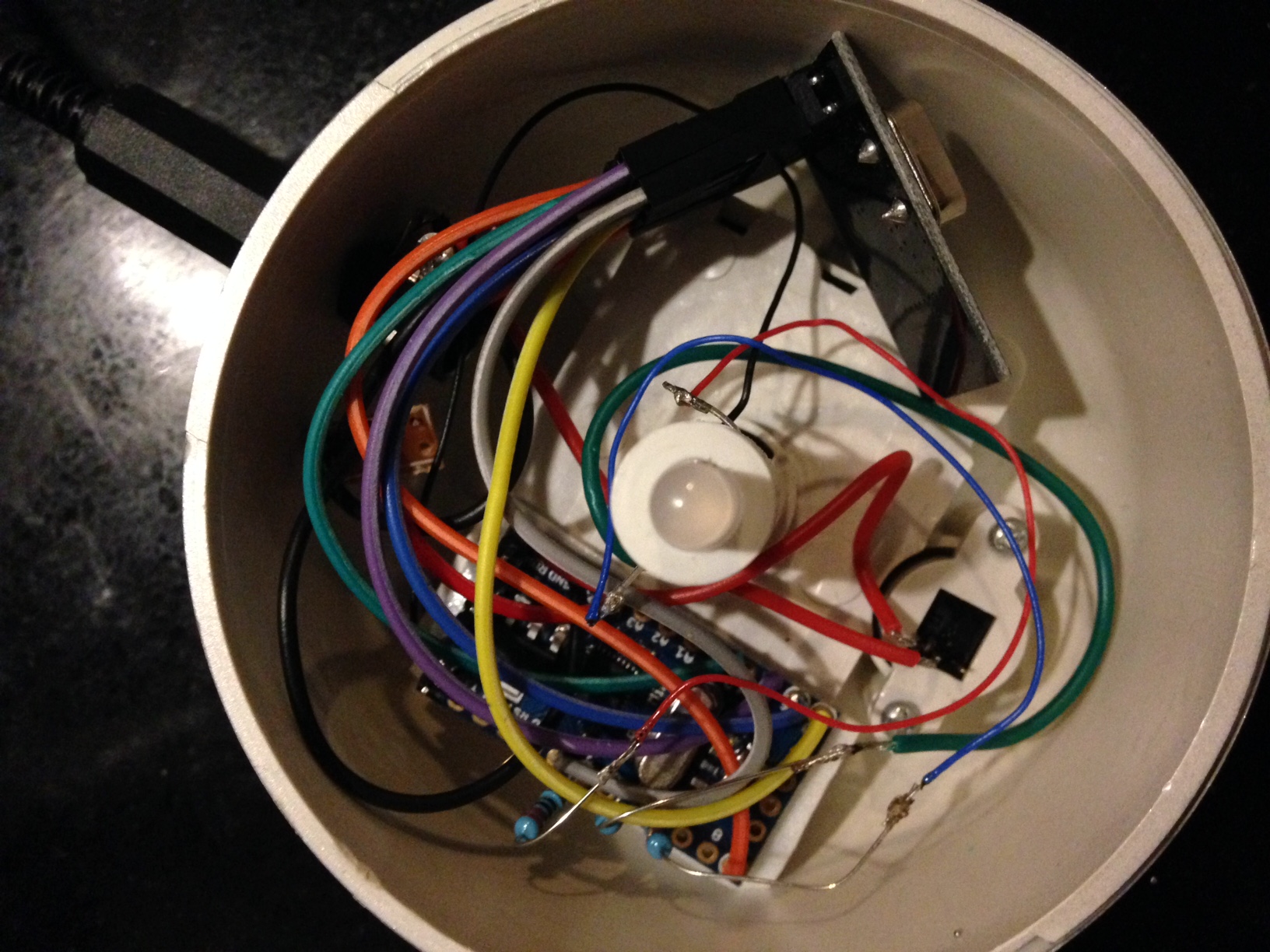
Also I soldered the 220 ohm resistors directly on the ProMini and soldered the LED wires to the resistor. I used double sided carpenters tape to stick the arduino on the lamp. Double sided tape is really strong. I use it to put my templates on wood, if I want to route a pattern in the wood. Believe me it's strong.
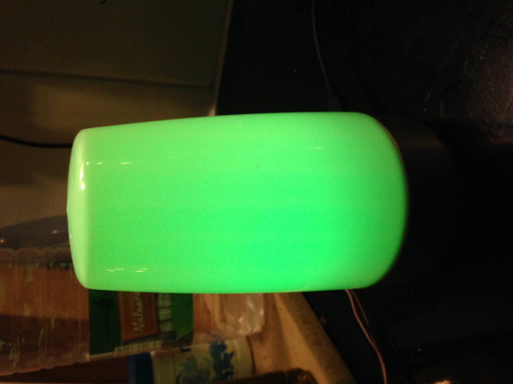
So here are some photo's of the mood-light in action.
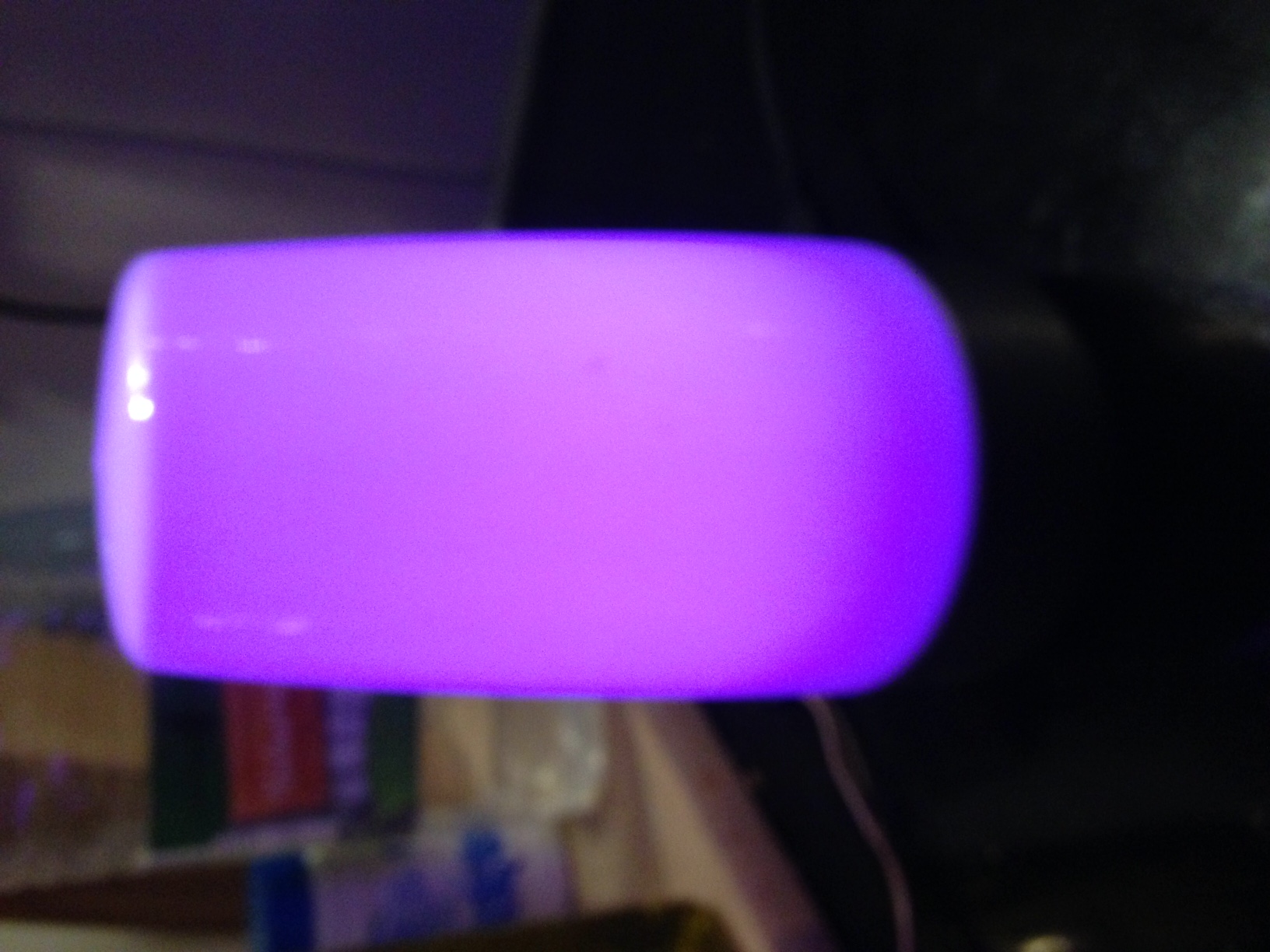
Sorry I wasn't able to rotate the photo's. The circuit is really easy. I power the NRF24L01 directly from the ProMini 3.3V. Each pin that is connected to the RGB led, connects through a 220Ohm resistor. I used pins 3, 5 and 6 to control the LED, because they're PWM pins.
I'll have to learn Fritzing. I've been playing with it, but I couldn't find the NRF24L01 component.
-
For anyone whois interested in how I mounted the electronics into the lamp. I posted an article about this on my blog http://www.houtbewerken-voor-dummies.com/grenzen-verleggen-een-moodlight/ it's in Dutch but you can translate this with google translator.
Hello! It looks like you're interested in this conversation, but you don't have an account yet.
Getting fed up of having to scroll through the same posts each visit? When you register for an account, you'll always come back to exactly where you were before, and choose to be notified of new replies (either via email, or push notification). You'll also be able to save bookmarks and upvote posts to show your appreciation to other community members.
With your input, this post could be even better 💗
Register Login