i2c Lightning Sensor +
-
AS3935 Lightning detector based on the playingwithfusion breakout board and includes a light control and also acts as a repeater node.
This design extends slightly on the original Lightning Detector node found here. As this will be my first outside node in range of my mysensors network I needed it to be a repeater as well. It will be mounted near a garden lamp post that I have converted to 12v and now uses LED's so I also wanted to use the node to control the light as well, this will also be a convenient place to get the 12v needed for the supply.
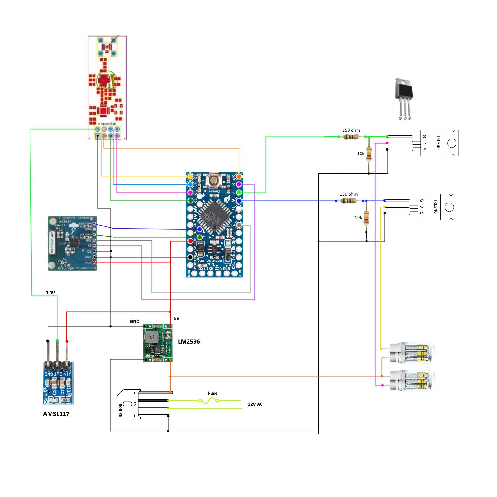
The basic circuit is shown below, in the final I intend to use a high powered NRF24L01+PA+LNA
module to maximise my range and hopefully extend my network across the yard area. If you use the high powered transceiver you will need to add an external 3.3v regulator as the nano on-board 3v regulator cannot supply enough current.
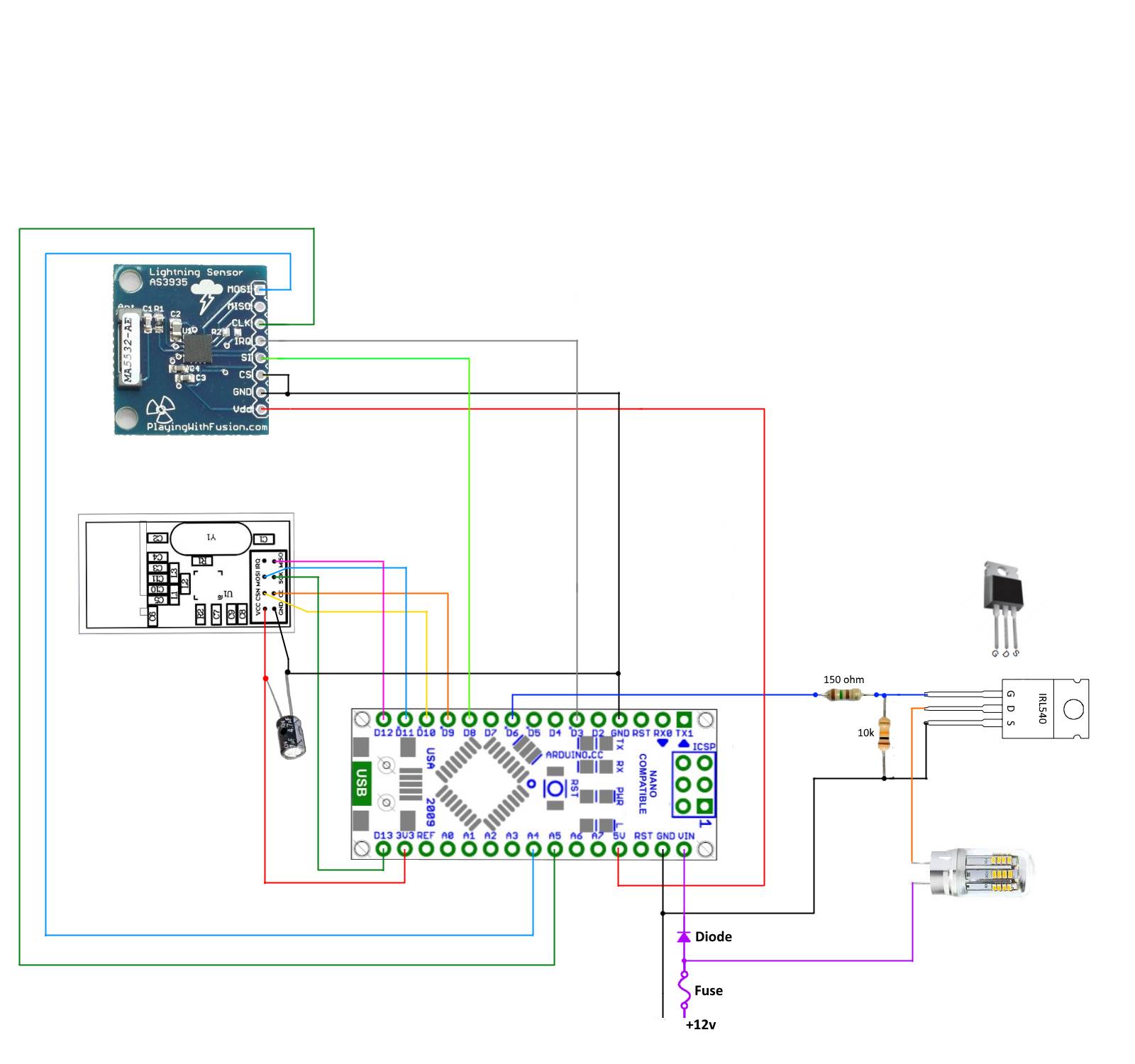
To guard against reverse polarity hookup I have used a 1n4001 diode on the input line to the nano. I have used a 150 ohm resistor as a current limiter to ptotect the Arduino and a 10k resistor to ensure the mosfet always switches completely off. The lightning board has built in 10k pullup resistors so none are needed on the A4 and A5 pins.
The transistor is an IRL540 Mosfet, which is designed to operate from logic level outputs like the nano. By using a device made to operate at logic levels means I should have no problem getting the mosfet to reach full saturation when being switched. Basically that means I should be able to switch a heavier load and generate less heat.
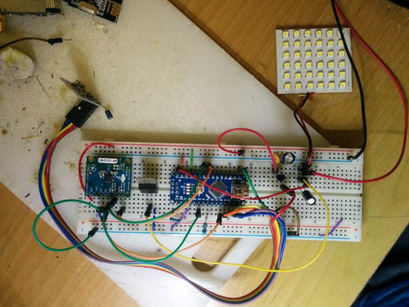
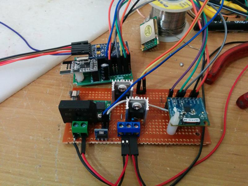
Here is the breadboard layout
The sketch
// This sketch is to integrate the Playing With Fusion AXS3935 Lightning Sensor Breakout Board
// with the MySensors environment and is based on a sketch provided by Playing With Fusion
// http://playingwithfusion.com/productview.php?pdid=22&catid=1001 and from the MySensors
// forum post at  https://forum.mysensors.org/topic/880/sketch-for-lightning-sensor
//As well as providing lightning detection this sketch now also alows node to act as
// a repeater and control an outdoor light that the node is mounted in.

#include "MySensor.h"
// the lightning sensor can communicate via SPI or I2C. This sketch uses the I2C interface
#include "I2C.h"
// include Playing With Fusion AXS3935 libraries
#include "PWFusion_AS3935_I2C.h"
#include "SPI.h"
// defines for hardware config
#define SI_PIN               8         // this pin will be switched high for i2c
#define IRQ_PIN              3        // digital pins 2 and 3 are available for interrupt capability
#define AS3935_ADD           0x03     // x03 - standard PWF SEN-39001-R01 config
#define AS3935_CAPACITANCE   48       // <-- SET THIS VALUE TO THE NUMBER LISTED ON YOUR BOARD
volatile int8_t AS3935_ISR_Trig = 0;

// #defines for general chip settings
#define AS3935_INDOORS       0
#define AS3935_OUTDOORS      1
#define AS3935_DIST_DIS      0
#define AS3935_DIST_EN       1

#define LIGHT_PIN  6  // Arduino Digital I/O pin number for Light
#define LIGHT_ON 1  // GPIO value to write to turn on attached relay
#define LIGHT_OFF 0 // GPIO value to write to turn off attached relay


// prototypes
void AS3935_ISR();

PWF_AS3935_I2C  lightning0((uint8_t)IRQ_PIN, (uint8_t)SI_PIN, (uint8_t)AS3935_ADD);

#define CHILD_ID_DISTANCE 1
#define CHILD_ID_INTENSITY 2
#define CHILD_ID_LIGHT 3

MySensor gw;
MyMessage msgDist(CHILD_ID_DISTANCE, V_DISTANCE);
MyMessage msgInt(CHILD_ID_INTENSITY, V_VAR1);
MyMessage msg(CHILD_ID_LIGHT,V_LIGHT);
void setup()
{
 // gw.begin();

  gw.begin(incomingMessage, AUTO, true);                      //  enable repeater mode.

  gw.sendSketchInfo("Lightning Sensor Plus", "1.0");   // Send the sketch version information to the gateway and Controller

  /*----Register all sensors to gw (they will be created as child devices----*/
  gw.present(CHILD_ID_DISTANCE, S_DISTANCE);
  gw.present(CHILD_ID_INTENSITY, S_CUSTOM);
  gw.present(CHILD_ID_LIGHT, S_LIGHT);
  pinMode(LIGHT_PIN, OUTPUT);            //set light pin as output
  digitalWrite(LIGHT_PIN, LIGHT_OFF);    //   make sure light is off at startup
 // Serial.begin(115200);
  Serial.println("Playing With Fusion: AS3935 Lightning Sensor, SEN-39001-R01");
  Serial.println("beginning boot procedure....");

 // setup for the the I2C library: (enable pullups, set speed to 400kHz)
  I2c.begin();
  I2c.pullup(true);
  I2c.setSpeed(1);
  delay(2);

  lightning0.AS3935_DefInit();            // set registers to default
  // now update sensor cal for your application and power up chip
  lightning0.AS3935_ManualCal(AS3935_CAPACITANCE, AS3935_OUTDOORS, AS3935_DIST_EN);
                  // AS3935_ManualCal Parameters:
                  //   --> capacitance, in pF (marked on package)
                  //   --> indoors/outdoors (AS3935_INDOORS:0 / AS3935_OUTDOORS:1)
                  //   --> disturbers (AS3935_DIST_EN:1 / AS3935_DIST_DIS:2)
                  // function also powers up the chip

  // enable interrupt (hook IRQ pin to Arduino Pro Mini, Nano, Uno/Mega interrupt input: 1 -> pin 3 )
  attachInterrupt(1, AS3935_ISR, RISING);
  // dump the registry data to the serial port for troubleshooting purposes
  lightning0.AS3935_PrintAllRegs();
  AS3935_ISR_Trig = 0;           // clear trigger
  // delay execution to allow chip to stabilize.
  delay(1000);

}

void loop()
{

  gw.process();          // By calling process() you route messages in the background
  // This program only handles an AS3935 lightning sensor. It does nothing until
  // an interrupt is detected on the IRQ pin.
  //while(0 == AS3935_ISR_Trig){}
 if (AS3935_ISR_Trig == 1){
  lightningDetected();
 }

}

// this is irq handler for AS3935 interrupts, has to return void and take no arguments
// always make code in interrupt handlers fast and short
void AS3935_ISR()
{
  AS3935_ISR_Trig = 1;
}

/*--------------Lightning function----------------*/
void lightningDetected(){
  // reset interrupt flag
  AS3935_ISR_Trig = 0;

  // now get interrupt source
  uint8_t int_src = lightning0.AS3935_GetInterruptSrc();
  if(0 == int_src)
  {
    Serial.println("Unknown interrupt source");
  }
  else if(1 == int_src)
  {
    uint8_t lightning_dist_km = lightning0.AS3935_GetLightningDistKm();
    uint32_t lightning_intensity = lightning0.AS3935_GetStrikeEnergyRaw();

    Serial.print("Lightning detected! Distance to strike: ");
    Serial.print(lightning_dist_km);
    Serial.println(" kilometers");
    Serial.print("Lightning detected! Lightning Intensity: ");
    Serial.println(lightning_intensity);
    gw.send(msgDist.set(lightning_dist_km));
    gw.send(msgInt.set(lightning_intensity));
  }
  else if(2 == int_src)
  {
    Serial.println("Disturber detected");
  }
  else if(3 == int_src)
  {
    Serial.println("Noise level too high");
  }
}


void incomingMessage(const MyMessage &message) {
  // We only expect one type of message from controller. But we better check anyway.
  if (message.type==V_LIGHT) {
     // Change relay state
     digitalWrite(LIGHT_PIN, message.getBool()?LIGHT_ON:LIGHT_OFF);

     // Write some debug info
     Serial.print("Incoming change for sensor:");
     Serial.print(message.sensor);
     Serial.print(", New status: ");
     Serial.println(message.getBool());
   }
}
I have found it hard to get good inexpensive outdoor cases that will endure the conditions for a long time. As I hope to deploy several outdoor nodes I wanted a case that would be as set and forget as possible without costing too much. I have decided to try and make my own so will see how this first one goes.
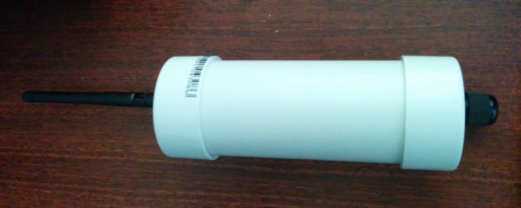
From the local hardware store I have purchased a length of 50mm pvc tubing and end caps to suit. I have cut the tube to suit the PCB of the lightning detector . I will then fit a waterproof cable gland to an end-cap and glue the end-cap to the bottom of the 50mm tube. I will leave the top as just push on with no glue and mount an aerial socket on there as well. The whole thing will be secured to a timber post with a 50mm clamp
Early days on this one, I will post more as it progresses.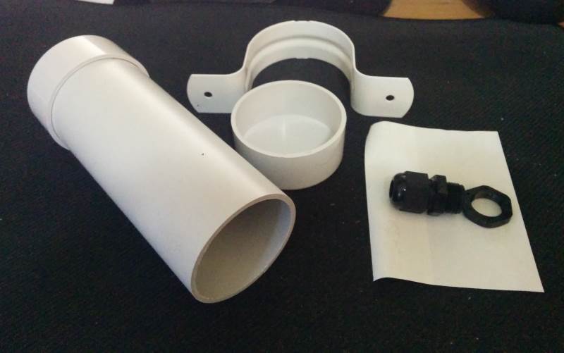
-
I have progressed a little further with this project an am nearly ready to install this one outside. I have changed the sketch to be MySensors V2 compliant and also added an extra mosfet to control a second set of garden lights as well. I remembered the garden lights run on 12v AC so had to include a rectifier in the circuit as well. Seems to run on the bench ok, but of course no storms to check the lightning . Will upload the new sketch and wiring soon.
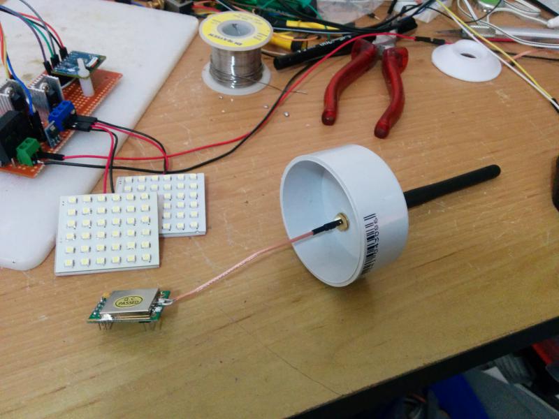
Antennae Mounted on lid. I am using a shielded nrf24l01+pa+lna module to increase the range. tests I have done with this one seem to be promising.
The main board with two mosfets
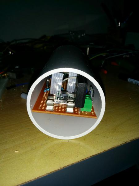
A good fit in the tube.
-
new diagram and sketch
// This sketch is to integrate the Playing With Fusion AXS3935 Lightning Sensor Breakout Board // with the MySensors V2 environment and is based on a sketch provided by Playing With Fusion // http://playingwithfusion.com/productview.php?pdid=22&catid=1001 and from the MySensors // forum post at https://forum.mysensors.org/topic/880/sketch-for-lightning-sensor //As well as providing lightning detection this sketch now also alows node to act as // a repeater and control two outdoor lights // Enable debug prints to serial monitor #define MY_DEBUG // Enable and select radio type attached #define MY_RADIO_NRF24 // Enabled repeater feature for this node #define MY_REPEATER_FEATURE // the lightning sensor can communicate via SPI or I2C. This sketch uses the I2C interface #include "I2C.h" // include Playing With Fusion AXS3935 libraries #include "PWFusion_AS3935_I2C.h" #include "SPI.h" #include <MySensors.h> // defines for hardware config #define SI_PIN 8 // this pin will be switched high for i2c #define IRQ_PIN 3 // digital pins 2 and 3 are available for interrupt capability #define AS3935_ADD 0x03 // x03 - standard PWF SEN-39001-R01 config #define AS3935_CAPACITANCE 48 // <-- SET THIS VALUE TO THE NUMBER LISTED ON YOUR BOARD volatile int8_t AS3935_ISR_Trig = 0; // #defines for general chip settings #define AS3935_INDOORS 0 #define AS3935_OUTDOORS 1 #define AS3935_DIST_DIS 0 #define AS3935_DIST_EN 1 #define LIGHT_PIN_A 6 // Arduino Digital I/O pin connected to mosfet 1 #define LIGHT_PIN_B 7 // Arduino Digital I/O pin connected to mosfet 2 #define LIGHT_ON 1 // GPIO value to write to turn on attached mosfet #define LIGHT_OFF 0 // GPIO value to write to turn off attached mosfet // prototypes void AS3935_ISR(); PWF_AS3935_I2C lightning0((uint8_t)IRQ_PIN, (uint8_t)SI_PIN, (uint8_t)AS3935_ADD); #define CHILD_ID_DISTANCE 1 #define CHILD_ID_INTENSITY 2 #define CHILD_ID_LIGHT_A 3 #define CHILD_ID_LIGHT_B 4 MyMessage msgDist(CHILD_ID_DISTANCE, V_DISTANCE); //MyMessage msgInt(CHILD_ID_INTENSITY, V_VAR1); MyMessage msgInt(CHILD_ID_INTENSITY, V_TEXT); void setup() { pinMode(LIGHT_PIN_A, OUTPUT); //set light pin as output pinMode(LIGHT_PIN_B, OUTPUT); //set light pin as output digitalWrite(LIGHT_PIN_A, LIGHT_OFF); // make sure light is off at startup digitalWrite(LIGHT_PIN_B, LIGHT_OFF); // make sure light is off at startup // Serial.begin(115200); Serial.println("Playing With Fusion: AS3935 Lightning Sensor, SEN-39001-R01"); Serial.println("beginning boot procedure...."); // setup for the the I2C library: (enable pullups, set speed to 400kHz) I2c.begin(); I2c.pullup(true); I2c.setSpeed(1); delay(2); lightning0.AS3935_DefInit(); // set registers to default // now update sensor cal for your application and power up chip lightning0.AS3935_ManualCal(AS3935_CAPACITANCE, AS3935_OUTDOORS, AS3935_DIST_EN); // AS3935_ManualCal Parameters: // --> capacitance, in pF (marked on package) // --> indoors/outdoors (AS3935_INDOORS:0 / AS3935_OUTDOORS:1) // --> disturbers (AS3935_DIST_EN:1 / AS3935_DIST_DIS:2) // function also powers up the chip // enable interrupt (hook IRQ pin to Arduino Pro Mini, Nano, Uno/Mega interrupt input: 1 -> pin 3 ) attachInterrupt(1, AS3935_ISR, RISING); // dump the registry data to the serial port for troubleshooting purposes lightning0.AS3935_PrintAllRegs(); AS3935_ISR_Trig = 0; // clear trigger // delay execution to allow chip to stabilize. delay(1000); } void presentation() { // Send the sketch version information to the gateway and Controller sendSketchInfo("Lightning Sensor Plus", "2.0"); // Register all sensors to gateway (they will be created as child devices) present(CHILD_ID_DISTANCE, S_DISTANCE,"Lightning Distance"); // present(CHILD_ID_INTENSITY, S_CUSTOM); present(CHILD_ID_INTENSITY, S_INFO,"Lightning Intensity"); present(CHILD_ID_LIGHT_A, S_LIGHT,"Lamp Post Light"); present(CHILD_ID_LIGHT_B, S_LIGHT,"Pool Lights"); } void loop() { // This program only handles an AS3935 lightning sensor. It does nothing until // an interrupt is detected on the IRQ pin. //while(0 == AS3935_ISR_Trig){} if (AS3935_ISR_Trig == 1){ lightningDetected(); // call the lighning function } } // this is irq handler for AS3935 interrupts, has to return void and take no arguments // always make code in interrupt handlers fast and short void AS3935_ISR() { AS3935_ISR_Trig = 1; } /*--------------Lightning function----------------*/ void lightningDetected(){ // reset interrupt flag AS3935_ISR_Trig = 0; // now get interrupt source uint8_t int_src = lightning0.AS3935_GetInterruptSrc(); if(0 == int_src) { Serial.println("Unknown interrupt source"); } else if(1 == int_src) { uint8_t lightning_dist_km = lightning0.AS3935_GetLightningDistKm(); uint32_t lightning_intensity = lightning0.AS3935_GetStrikeEnergyRaw(); Serial.print("Lightning detected! Distance to strike: "); Serial.print(lightning_dist_km); Serial.println(" kilometers"); Serial.print("Lightning detected! Lightning Intensity: "); Serial.println(lightning_intensity); send(msgDist.set(lightning_dist_km)); send(msgInt.set(lightning_intensity)); } else if(2 == int_src) { Serial.println("Disturber detected"); } else if(3 == int_src) { Serial.println("Noise level too high"); } } void receive(const MyMessage &message) { // We only expect one type of message from controller. But we better check anyway. if (message.type==V_LIGHT) { // Change relay state digitalWrite(message.sensor+3, message.getBool()?LIGHT_ON:LIGHT_OFF); // Write some debug info Serial.print("Incoming change for sensor:"); Serial.print(message.sensor); Serial.print(", New status: "); Serial.println(message.getBool()); } } -
Well it is now installed outside so i just have to wait for a storm to see if it performs as expected. I have made a slight change to the V2 sketch and am using V_TEXT for intensity for now, at least i can see that in Domoticz.
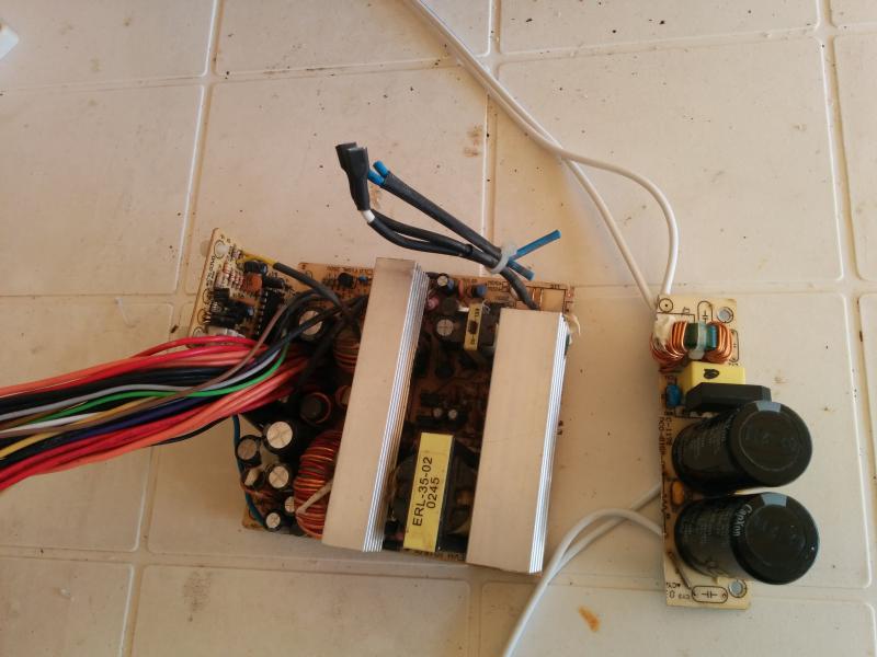
The installation went well except for when I connected it up to the 12v AC the lightning sensor started producing a constant stream of disturber hits, worked fine when on battery so I guess there was too much noise from the AC. The solution was to up-cycle part of an old PC power supply, to my surprise this worked really well and the sensor is now very stable.
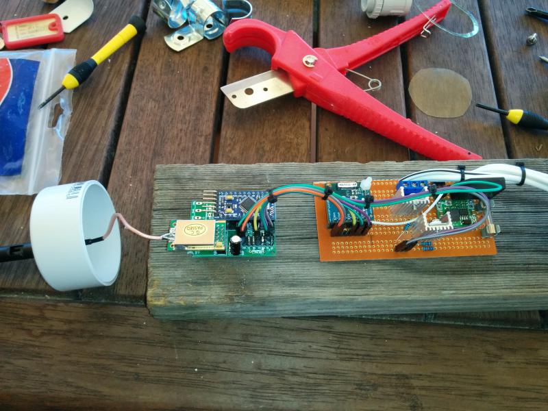
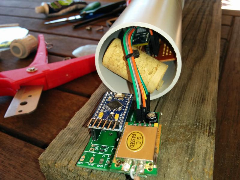
All ready to go into the tube
I used an old cork to keep the boards apart. When the boards are in the tube I can still get to the top of the pro-mini for easy updating of sketches.
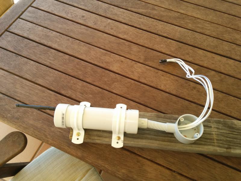
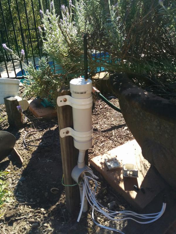
The final product ready to be mounted in the garden. I ended up with a junction box below the main sensor as there were several wires to connect up it would have been too hard to do in the sensor. Plus this will allow me to physically change what lights the sensor controls without dis-assembling the sensor.
The sensor has already been through some heavy rain without an problems so I think this will be a good (and reasonably cheap) design for the garden.
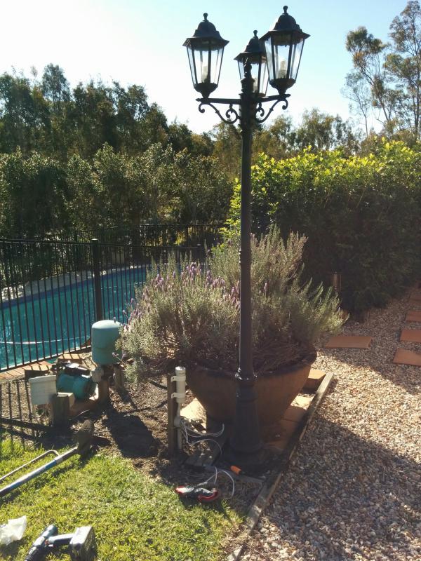
Here is the light it now controls
Here is the old PC power supply that I used. The filter section was at the end of the board so I just sliced it off with my Dremel and attached some wires. A word of warning, the capacitors in these things will hold a mains charge for a long time so you must be careful to make sure they are discharged before you touch anything inside.
-
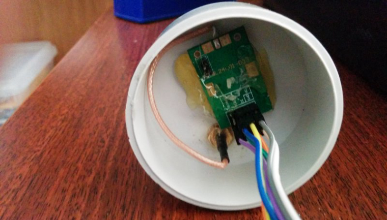
Just an update on this project. It took a while but we finally entered the storm season a couple of months back. This allowed me to get some real world data at last which has led to a few changes to this project. Firstly I have moved the Lightning sensor to its own housing with no other sensors/actuators. The reason for this is I would occasionally get false lightning strikes when the switches were operated.
I have also made a few changes to the sketch. I now use the dust sensor for both distance and intensity readings, this gives a better display in Domoticz and of course I no longer needed the code for the switches etc. This code is working on MySensors V2.1.1
I have mounted it all on a new board and have fitted it to one of my tube cases. These cases by the way are working out great for outside housings. I have a few scattered around the yard now and they have all performed well through our wet season, no signs of water in them at all and very easy to get at the arduino if i need to.
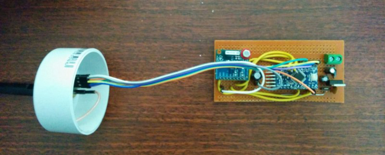
I hot glued the NRF to the lid
And then it all just slips into the tube
I am still using i2c for the interface. It has been interesting watching the readouts as storms approach.
The Sketch:
/* This sketch is to integrate the Playing With Fusion AXS3935 Lightning Sensor Breakout Board * with the MySensors V2 environment and is based on a sketch provided by Playing With Fusion * http://playingwithfusion.com/productview.php?pdid=22&catid=1001 and from the MySensors * forum post at https://forum.mysensors.org/topic/880/sketch-for-lightning-sensor * * Circuit: * Arduino Uno --> SEN-39001: AS3935 Breakout * SDA: SDA --> MOSI/SDA (SDA is labeled on the bottom of the Arduino) * SCLK: SCL --> SCK/SCL (SCL is labeled on the bottom of the Arduino) * SI: pin 8 --> SI (select interface; GND=SPI, VDD=I2C * IRQ: pin 3 --> IRQ * GND: GND --> CS (pull CS to ground even though it's not used) * GND: GND --> GND * 5V: 5V --> Arduino I/O is at 5V, so power board from 5V. Can use 3.3V with Due, etc */ // Enable debug prints to serial monitor #define MY_DEBUG // Enable and select radio type attached #define MY_RADIO_NRF24 // Enabled repeater feature for this node #define MY_REPEATER_FEATURE #define MY_NODE_ID 11 #define MY_RF24_CHANNEL 84 #define MY_TRANSPORT_WAIT_READY_MS 3000 //set how long to wait for transport ready. #include "I2C.h" // the lightning sensor can communicate via SPI or I2C. This sketch uses the I2C interface #include "PWFusion_AS3935_I2C.h" // include Playing With Fusion AXS3935 libraries #include "SPI.h" #include <MySensors.h> /*------- defines for hardware config---------*/ #define SI_PIN 8 // this pin will be switched high for i2c #define IRQ_PIN 3 // digital pins 2 and 3 are available for interrupt capability #define AS3935_ADD 0x03 // x03 - standard PWF SEN-39001-R01 config #define AS3935_CAPACITANCE 48 // <-- SET THIS VALUE TO THE NUMBER LISTED ON YOUR BOARD volatile int8_t AS3935_ISR_Trig = 0; /*---- #defines for general chip settings----*/ #define AS3935_INDOORS 0 //use this setting if the sensor is indoors... more sensitive #define AS3935_OUTDOORS 1 //use this for sensor outdoors... less sensitive #define AS3935_DIST_DIS 0 // dissable disturber reporting #define AS3935_DIST_EN 1 // enable disturber reporting.... handy when setting up // prototypes void AS3935_ISR(); PWF_AS3935_I2C lightning0((uint8_t)IRQ_PIN, (uint8_t)SI_PIN, (uint8_t)AS3935_ADD); #define CHILD_ID_DISTANCE 1 #define CHILD_ID_INTENSITY 2 unsigned long heartbeatDelay = 120; // how often the heartbeat will be sent, in minutes unsigned long lastHeartbeat = millis(); // holder for last time heartbeat was sent MyMessage msgDist(CHILD_ID_DISTANCE, V_LEVEL); MyMessage msgInt(CHILD_ID_INTENSITY, V_LEVEL); void setup() { Serial.println("Playing With Fusion: AS3935 Lightning Sensor, SEN-39001-R01"); Serial.println("beginning boot procedure...."); /* setup for the the I2C library: (enable pullups, set speed to 400kHz) */ I2c.begin(); I2c.pullup(true); I2c.setSpeed(1); //delay(2); wait(2); lightning0.AS3935_DefInit(); // set registers to default // now update sensor cal for your application and power up chip lightning0.AS3935_ManualCal(AS3935_CAPACITANCE, AS3935_OUTDOORS, AS3935_DIST_DIS); // capacitance , inside or outside , disturbers enabled or disabled // AS3935_ManualCal Parameters: // --> capacitance, in pF (marked on package) // --> indoors/outdoors (AS3935_INDOORS:0 / AS3935_OUTDOORS:1) // --> disturbers (AS3935_DIST_EN:1 / AS3935_DIST_DIS:0) // function also powers up the chip // enable interrupt (hook IRQ pin to Arduino Pro Mini, Nano, Uno/Mega interrupt input: 0 -> pin 2, 1 -> pin 3 ) attachInterrupt(1, AS3935_ISR, RISING); // dump the registry data to the serial port for troubleshooting purposes lightning0.AS3935_PrintAllRegs(); AS3935_ISR_Trig = 0; // clear trigger // delay execution to allow chip to stabilize. //delay(1000); wait(1000); } void presentation() { // Send the sketch version information to the gateway and Controller sendSketchInfo("Lightning Sensor", "1.0"); // Register all sensors to gateway (they will be created as child devices) present(CHILD_ID_DISTANCE, S_DUST, "Lightning Distance"); present(CHILD_ID_INTENSITY, S_DUST, "Lightning Intensity"); } void loop() { if ( AS3935_ISR_Trig == 1){ // check to see if interrupt triggered wait(5); lightningDetected(); // call the lightning function } // wait(5); heartbeatCheck(); // call heartbeat function } /*-------------------------start of functions-------------------*/ void heartbeatCheck(){ unsigned long millisNow = millis(); // get the current time if ((millisNow - lastHeartbeat) > (heartbeatDelay*60000)) { sendHeartbeat(); lastHeartbeat = millis(); #ifdef MY_DEBUG Serial.println("Heartbeat Sent" ); #endif } } // this is irq handler for AS3935 interrupts, has to return void and take no arguments // always make code in interrupt handlers fast and short void AS3935_ISR() { AS3935_ISR_Trig = 1; } /*--------------Lightning function----------------*/ void lightningDetected() { AS3935_ISR_Trig = 0; // reset interrupt flag uint8_t int_src = lightning0.AS3935_GetInterruptSrc(); // now get interrupt source /*---0 = Unknown, 1 = Lightning detected, 2 = Disturber detected, 3 = Noise level too high ---*/ switch (int_src) { case 0: { #ifdef MY_DEBUG Serial.println("Unknown interrupt source"); #endif } break; case 1: { uint8_t lightning_dist_km = lightning0.AS3935_GetLightningDistKm(); uint32_t lightning_intensity = lightning0.AS3935_GetStrikeEnergyRaw(); #ifdef MY_DEBUG Serial.print("Lightning detected! Distance to strike: "); Serial.print(lightning_dist_km); Serial.println(" kilometers"); Serial.print("Lightning detected! Lightning Intensity: "); Serial.println(lightning_intensity); #endif send(msgDist.set(lightning_dist_km)); wait (10); send(msgInt.set(lightning_intensity)); } break; case 2: { #ifdef MY_DEBUG Serial.println("Disturber detected"); #endif } break; case 3: { #ifdef MY_DEBUG Serial.println("Noise level too high"); #endif } break; } } -
How much did you pay for the sensor? I looked around and that's not very cheap for such small board. Does the library only works for that specific vendor or is it universal as long as the same chip is used of course?
-
How much did you pay for the sensor? I looked around and that's not very cheap for such small board. Does the library only works for that specific vendor or is it universal as long as the same chip is used of course?
@gohan I can't remember the exact price, i think it was around $40 back then. They are a little cheaper now I Have a weather station setup so it was a nice addition.
The Library is written to work with their module although you could probably use it as a base if you had the same chip from another supplier. The playingwithfusion modules come pre calibrated which makes them a breeze to use. There are other modules also available with their own libraries as well. -
Hello Boots33,
I flashed your sketch in an Arduino pro mini, it is registering but "both" sensors did not show in Domoticz. I had to trigger them (send a msg with values) after that Domoticz showed them both. The heartbeat is working from the mysensors point of view, confirmation from the Arduino monitor and a led flashing on the pro mini (I activated the err, tx, rx option) but Domoticz won't register the heartbeat, can you confirm that?
Regards
Frank -
Hello Boots33,
I flashed your sketch in an Arduino pro mini, it is registering but "both" sensors did not show in Domoticz. I had to trigger them (send a msg with values) after that Domoticz showed them both. The heartbeat is working from the mysensors point of view, confirmation from the Arduino monitor and a led flashing on the pro mini (I activated the err, tx, rx option) but Domoticz won't register the heartbeat, can you confirm that?
Regards
Frank@YFandS said in i2c Lightning Sensor +:
Hello Boots33,
I flashed your sketch in an Arduino pro mini, it is registering but "both" sensors did not show in Domoticz. I had to trigger >them (send a msg with values) after that Domoticz showed them both.
Yes that is a Domoticz thing i think. the node and sensors will show up in the mysensors hardware device after being presented but the sensors will not be seen in the Devices list until they have sent some data. Domoticz will do this with other sensors as well.
The heartbeat is working from the mysensors point of view, confirmation from the Arduino monitor and a led flashing on >the pro mini (I activated the err, tx, rx option) but Domoticz won't register the heartbeat, can you confirm that?
I experienced the same issue, as you said the heartbeat message is shown to be sent in the serial monitor but no update is registered in domoticz. At the time i thought it would be something at the Domoticz end and would be fixed in a future release. I am fairly sure i am using heartbeat correctly. If someone can shed some light on this i would be grateful.
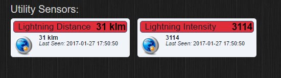
Sorry I have been a bit remiss with this project, I should have mentioned this in a followup post.
I have been meaning to modify the sketch a bit anyway as I am not completely happy with how the data is shown. At the moment the data displays the last strike until new data is available. This means even if there is no lightning around you will still see the most recent strike data.
I would prefer the display to be reset after a period of time until the next storm period. I think I will use this to both clear the display and also be used as a heartbeat. It will only need minor changes to the current heartbeatCheck function.
One last thing I found that even though my sensor is outdoors i get the best results using AS3935_INDOORS in the setup line. :)
-
Thank for the reply,
I found this online: https://github.com/domoticz/domoticz/issues/1396
march 23, 2017the short version is:
gizmocuz commented on 25 MarCould be around the switch case 492, i am only handling the heartbeat for the following value types:
		case V_TRIPPED:
		case V_ARMED:
		case V_LOCK_STATUS:
		case V_STATUS:
		case V_PERCENTAGE:
		case V_SCENE_ON:
		case V_SCENE_OFF:
		case V_UP:
		case V_DOWN:
		case V_STOP:
		case V_RGB:
		case V_RGBW:
Maybe we miss some... it could be a complicated issue to support all types, as for all types we should recover the IDX in the database, or we should remember this...
End
I checked the Domoticz source files and still no change (11 sep 2017) so no heartbeat with v_values.Regards
Frank -
I have made the changes I mentioned above. The node now resets the lightning data to 0 every hour. This I hope will give a more meaningful log over time and also provide a heartbeat to indicate the node is functioning. If lightning is detected the data reset timer begins its count from the beginning, this is to stop the data from being reset too soon.
/* This sketch is to integrate the Playing With Fusion AXS3935 Lightning Sensor Breakout Board * with the MySensors V2 environment and is based on a sketch provided by Playing With Fusion * http://playingwithfusion.com/productview.php?pdid=22&catid=1001 and from the MySensors * forum post at https://forum.mysensors.org/topic/880/sketch-for-lightning-sensor * * Circuit: * Arduino Uno --> SEN-39001: AS3935 Breakout * SDA: SDA --> MOSI/SDA (SDA is labeled on the bottom of the Arduino) * SCLK: SCL --> SCK/SCL (SCL is labeled on the bottom of the Arduino) * SI: pin 8 --> SI (select interface; GND=SPI, VDD=I2C * IRQ: pin 3 --> IRQ * GND: GND --> CS (pull CS to ground even though it's not used) * GND: GND --> GND * 5V: 5V --> Arduino I/O is at 5V, so power board from 5V. Can use 3.3V with Due, etc */ // Enable debug prints to serial monitor #define MY_DEBUG // Enable and select radio type attached #define MY_RADIO_NRF24 // Enabled repeater feature for this node #define MY_REPEATER_FEATURE #define MY_NODE_ID 11 #define MY_RF24_CHANNEL 84 #define MY_TRANSPORT_WAIT_READY_MS 3000 //set how long to wait for transport ready. #include "I2C.h" // the lightning sensor can communicate via SPI or I2C. This sketch uses the I2C interface #include "PWFusion_AS3935_I2C.h" // include Playing With Fusion AXS3935 libraries #include "SPI.h" #include <MySensors.h> /*------- defines for hardware config---------*/ #define SI_PIN 8 // this pin will be switched high for i2c #define IRQ_PIN 3 // digital pins 2 and 3 are available for interrupt capability #define AS3935_ADD 0x03 // x03 - standard PWF SEN-39001-R01 config #define AS3935_CAPACITANCE 48 // <-- SET THIS VALUE TO THE NUMBER LISTED ON YOUR BOARD volatile int8_t AS3935_ISR_Trig = 0; /*---- #defines for general chip settings----*/ #define AS3935_INDOORS 0 //use this setting if the sensor is indoors... more sensitive #define AS3935_OUTDOORS 1 //use this for sensor outdoors... less sensitive #define AS3935_DIST_DIS 0 // dissable disturber reporting #define AS3935_DIST_EN 1 // enable disturber reporting.... handy when setting up // prototypes void AS3935_ISR(); PWF_AS3935_I2C lightning0((uint8_t)IRQ_PIN, (uint8_t)SI_PIN, (uint8_t)AS3935_ADD); #define CHILD_ID_DISTANCE 1 #define CHILD_ID_INTENSITY 2 unsigned long lastReset = millis(); // holder for last time reset was triggered unsigned long resetTime = 60; // time between data resets in minutes bool firstBoot = true; MyMessage msgDist(CHILD_ID_DISTANCE, V_LEVEL); MyMessage msgInt(CHILD_ID_INTENSITY, V_LEVEL); void setup() { Serial.println("Playing With Fusion: AS3935 Lightning Sensor, SEN-39001-R01"); Serial.println("beginning boot procedure...."); /* setup for the the I2C library: (enable pullups, set speed to 400kHz) */ I2c.begin(); I2c.pullup(true); I2c.setSpeed(1); wait(2); lightning0.AS3935_DefInit(); // set registers to default // now update sensor cal for your application and power up chip lightning0.AS3935_ManualCal(AS3935_CAPACITANCE, AS3935_INDOORS, AS3935_DIST_EN); // capacitance , inside or outside , disturbers enabled or disabled // AS3935_ManualCal Parameters: // --> capacitance, in pF (marked on package) // --> indoors/outdoors (AS3935_INDOORS:0 / AS3935_OUTDOORS:1) // --> disturbers (AS3935_DIST_EN:1 / AS3935_DIST_DIS:0) // function also powers up the chip // enable interrupt (hook IRQ pin to Arduino Pro Mini, Nano, Uno/Mega interrupt input: 0 -> pin 2, 1 -> pin 3 ) attachInterrupt(1, AS3935_ISR, RISING); // dump the registry data to the serial port for troubleshooting purposes lightning0.AS3935_PrintAllRegs(); AS3935_ISR_Trig = 0; // clear trigger wait(1000); // delay execution to allow chip to stabilize. } void presentation() { // Send the sketch version information to the gateway and Controller sendSketchInfo("Lightning Sensor", "1.1"); // Register all sensors to gateway (they will be created as child devices) present(CHILD_ID_DISTANCE, S_DUST, "Lightning Distance"); present(CHILD_ID_INTENSITY, S_DUST, "Lightning Intensity"); } void loop() { if (firstBoot){ //When node first boots clear the lightning data send(msgDist.set(0)); wait (10); send(msgInt.set(0)); firstBoot = false; } // This program only handles an AS3935 lightning sensor. It does nothing until // an interrupt is detected on the IRQ pin. //while(0 == AS3935_ISR_Trig){} // wait(5); if ( AS3935_ISR_Trig == 1){ wait(5); lightningDetected(); // call the lighning function } // wait(5); resetCheck(); // call data reset function } /*-------------------------start of functions-------------------*/ void resetCheck(){ unsigned long millisNow = millis(); // get the current time if ((millisNow - lastReset) > (resetTime*60000)) { lastReset = millis(); send(msgDist.set(0)); // send lightning distance wait (10); send(msgInt.set(0)); // send lightning intensity } } // this is irq handler for AS3935 interrupts, has to return void and take no arguments // always make code in interrupt handlers fast and short void AS3935_ISR() { AS3935_ISR_Trig = 1; } /*--------------Lightning function----------------*/ void lightningDetected() { AS3935_ISR_Trig = 0; // reset interrupt flag uint8_t int_src = lightning0.AS3935_GetInterruptSrc(); // now get interrupt source /*---0 = Unknown, 1 = Lightning detected, 2 = Disturber detected, 3 = Noise level too high ---*/ switch (int_src) { case 0: { #ifdef MY_DEBUG Serial.println("Unknown interrupt source"); #endif } break; case 1: { uint8_t lightning_dist_km = lightning0.AS3935_GetLightningDistKm(); uint32_t lightning_intensity = lightning0.AS3935_GetStrikeEnergyRaw(); #ifdef MY_DEBUG Serial.print("Lightning detected! Distance to strike: "); Serial.print(lightning_dist_km); Serial.println(" kilometers"); Serial.print("Lightning detected! Lightning Intensity: "); Serial.println(lightning_intensity); #endif send(msgDist.set(lightning_dist_km)); wait (10); send(msgInt.set(lightning_intensity)); lastReset = millis(); } break; case 2: { #ifdef MY_DEBUG Serial.println("Disturber detected"); #endif } break; case 3: { #ifdef MY_DEBUG Serial.println("Noise level too high"); #endif } break; } } -
@boots33 said in i2c Lightning Sensor +:
#include "I2C.h" // the lightning sensor can communicate via SPI or I2C. This sketch uses the I2C interface
I mean this:
#include "I2C.h" // the lightning sensor can communicate via SPI or I2C. This sketch uses the I2C interface
Hello! It looks like you're interested in this conversation, but you don't have an account yet.
Getting fed up of having to scroll through the same posts each visit? When you register for an account, you'll always come back to exactly where you were before, and choose to be notified of new replies (either via email, or push notification). You'll also be able to save bookmarks and upvote posts to show your appreciation to other community members.
With your input, this post could be even better 💗
Register Login