Single button operated Led Strip Dimmer
-
Since i wanted to integrate a dimming led strip in my existing house electrical system i did create the following projected.
It had to:
- fit in my electrical wiring (so need to pull additional wires)
- single button operation (standard house switch)
- full MySensors dimming and control features
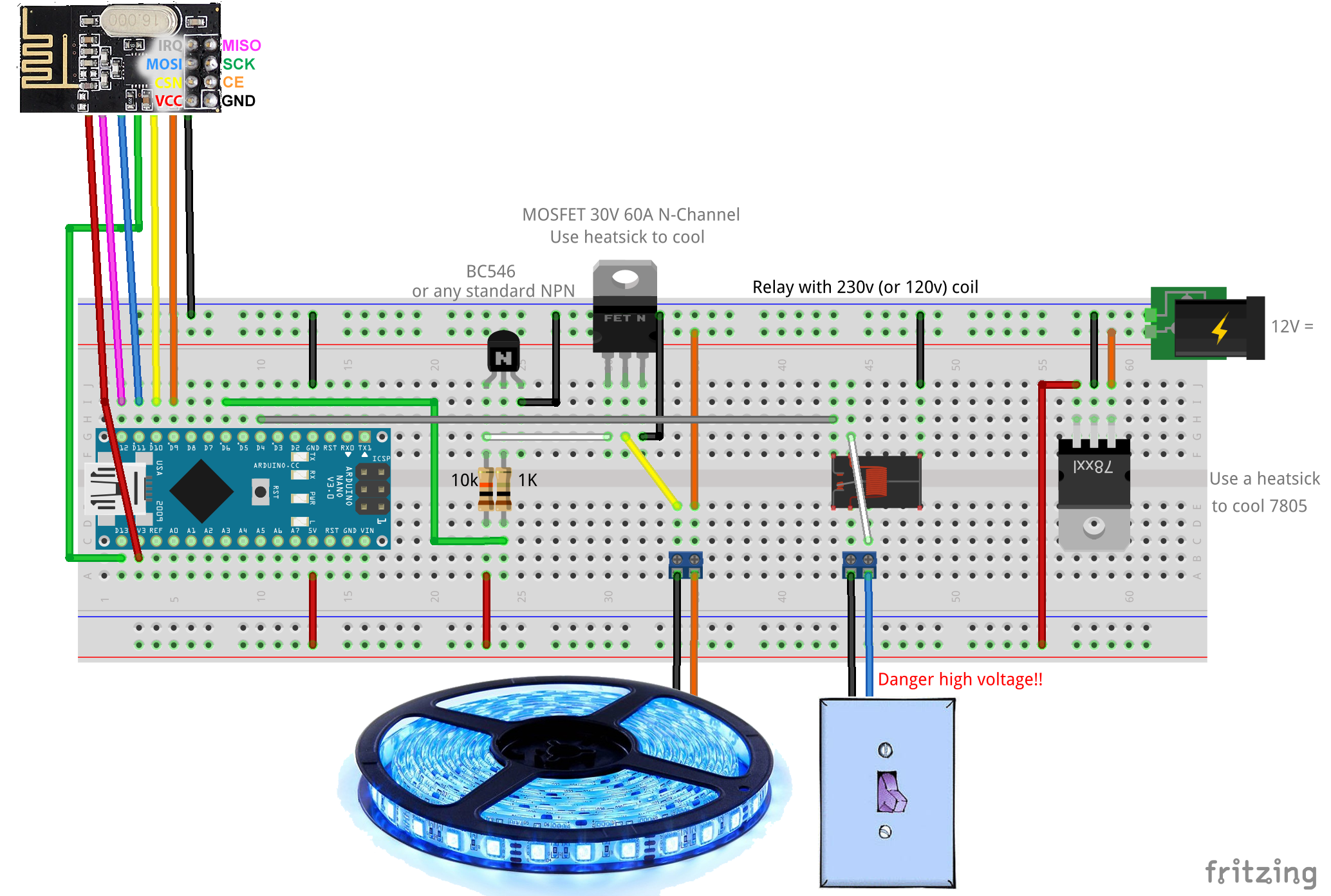
During development i discovered that (in my situation) the standard LED strip dimmer did not reach 12 volt @ 100% dim level (digitalWrite(pin, 255)) so a had to added a extra NPN transistor to reach the full 12 volt an thus maximum light. "Down site" of this extra transistor an inverted dim control so digitalWrite(pin, 255) will give no light and digitalWrite(pin, 0) 100%.
To make use of the standard in-wall switch i added a relay with a 230v coil controlling a 5 volt input pin a to signal the Arduino
This is the electrical prototype scheme:
It operates like this:
- Just toggling the switch will light the LED-(strip) smooth to 100% level or back to 0% when turning the light off.
- By a short ON-OFF switch-pulse the LED will dim to the last set dim level when it was OFF or dim to 0% when the LED was on.
- Setting a new target dim level can be done by keeping the switch on until it reaches the desired dim-level and the switch OFF again.
- Now the LED will stay on keeping the dim level
- In all situations your home automation controller will be informed on the changing situations and off course can override the switch situation
This sketch controls 2 LED-(strips) but can be easily extended by adding a LEDS entry to the led array (on line 67) the amount of leds is limited by the amount of PWM pins on your Arduino this is 6 (pin#3,5,6, 9,10,11), but 3 of these PWN pins (9.10,11) are occupied by the radio (NRF24L01), were pin 9 of the radio can be remapped
For the switch input both analog (Ax) and digital (Dx) pins can be usedThe dim level can be set linear i.s.o. logarithmic (for your eyes this will look more linear)
/** * REVISION HISTORY * Version 1.0 - February 15, 2014 - Bruce Lacey * Version 1.1 - August 13, 2014 - Converted to 1.4 (hek) * Version 1.2 - Januari 2016 - Bart Eversdijk * * DESCRIPTION * This sketch provides a Dimmable LED Light using PWM and based on Henrik Ekblad * <henrik.ekblad@gmail.com> Vera Arduino Sensor project. * Developed by Bruce Lacey, inspired by Hek's MySensor's example sketches. * * The circuit uses a MOSFET for Pulse-Wave-Modulation to dim the attached LED or LED strip. * The MOSFET Gate pin is connected to Arduino pin 3 (LED_PIN), the MOSFET Drain pin is connected * to the LED negative terminal and the MOSFET Source pin is connected to ground. * * V1.2 Additions: * control by normal ON/OFF switch * The sketch is now optimized for integration in an existing house wiring situation, Where a standard light switch can be used to control * the dimmer. Just toggling the switch will light the LED-(strip) smooth to 100% level or back to 0% when turning the light off. * By a short ON-OFF switch-pulse the LED will dim to the last set dim level (when it was OFF) or dim to 0% when the LED was on. * Setting a new target dim level can be done by keeping the switch on until it reaches the desired dim-level and the switch OFF again. * Now the LED will stay on keeping the dim level. * In all situations your home automation controller will be informed on the changing situations and off course can override the switch situation * * This sketch controls 2 LED-(strips) but can be easily extended by adding a LEDS entry to the led array (on line 70) * The dim level can be set linear i.s.o. logarithmic (for your eyes this will look more linear) * * http://www.mysensors.org/build/dimmer */ #include <MySensor.h> #include <SPI.h> #include <Bounce2.h> #include <math.h> #define LED1_PIN 6 // Arduino pin attached to MOSFET Gate pin #define SW1_PIN 4 #define LED2_PIN 3 // Arduino pin attached to MOSFET Gate pin #define SW2_PIN 2 #define MYS_INIT_DELAY 500 #define FADE_DELAY 10 // Delay in ms for each percentage fade up/down (10ms = 1s full-range dim) enum DIMCURVES { DIM_LINEAR = 0, // Normal linear curve DIM_LINEAR_INV, // Inverted linear curve DIM_LOGARITHMIC, // Normal logarithmic curve DIM_LOGARITHMIC_INV, // Inverted logarithmic curve DIM_CUSTOM // Define your own dimming curve }; struct LEDS { int currentLevel; // Current dim level int toLevel; // Level to dim to Bounce debouncer; int LedPin; int SwitchPin; byte switchValue; int savedLevel; // level to dim to when on is pressed int switchCount; bool ignoreNextSw; // if true ignore next OFF switch (was overriden by controller in ON state) DIMCURVES dimcurve; // Set the dim curve mode (linear, logarithmic, inverted, custom) MyMessage dimmerMsg; MyMessage lightMsg; }; LEDS led[] = { {0, 0, Bounce(), LED1_PIN, SW1_PIN, 0, 100, 0, false, DIM_LINEAR_INV, MyMessage(0, V_DIMMER), MyMessage(0, V_LIGHT)}, {0, 0, Bounce(), LED2_PIN, SW2_PIN, 0, 100, 0, false, DIM_CUSTOM, MyMessage(1, V_DIMMER), MyMessage(1, V_LIGHT)} }; #define MAXLED (sizeof(led)/sizeof(LEDS)) MySensor gw; /*** * Dimmable LED initialization method */ void setup() { // Switch off all leds for (byte id = 0; id < MAXLED; id++) { pinMode(led[id].LedPin, OUTPUT); setLedLevel(id); } gw.begin( incomingMessage ); // Register the LED Dimmable Light with the gateway for (byte id = 0; id < MAXLED; id++) { pinMode(led[id].SwitchPin, INPUT); // Activate internal pull-up digitalWrite(led[id].SwitchPin, HIGH); gw.present( id, S_DIMMER ); delay( MYS_INIT_DELAY ); // Pull the gateway's current dim level - restore light level upon sendor node power-up gw.request( id, V_DIMMER ); delay( MYS_INIT_DELAY ); // After setting up the button, setup debouncer led[id].debouncer.attach(led[id].SwitchPin); led[id].debouncer.interval(5); } gw.sendSketchInfo("1.2", "LedStripSwitch"); } /*** * Dimmable LED main processing loop */ void loop() { gw.process(); for (byte id = 0; id < MAXLED; id++) { // If target level is not reached fade a little bit more if (led[id].currentLevel != led[id].toLevel) { led[id].currentLevel += ((led[id].toLevel - led[id].currentLevel ) < 0 ? -1 : 1); setLedLevel(id); } // Check debounced button led[id].debouncer.update(); byte switchValue = led[id].debouncer.read() ? 0 : 1; // Inverted signal // Button change detected if (led[id].switchValue != switchValue) { Serial.print (F("Switch ")); Serial.println (switchValue); led[id].switchValue = switchValue; // If key released switch on when off or off when on --> when we where fading (above 100 steps) this is the end state // When we just left the button (> 500) we now turning the lights off again if (!switchValue && !led[id].ignoreNextSw) { if (led[id].switchCount <= 100 || led[id].switchCount > 500) { led[id].toLevel = (led[id].currentLevel ? 0 : led[id].savedLevel); } else { led[id].savedLevel = led[id].toLevel; // Store new saved level } // Inform the gateway of the current DimmableLED's SwitchPower1 and LoadLevelStatus value... gw.send(led[id].lightMsg.set(led[id].toLevel > 0 ? 1 : 0)); gw.send(led[id].dimmerMsg.set(led[id].toLevel) ); } led[id].ignoreNextSw = false; led[id].switchCount = 0; } else if (switchValue && led[id].switchCount <= 500) { // Keep counting until we reached 500 (@ 500 we asume we are in switch ON / OFF mode) led[id].switchCount++; // So this in not just a switch on (or off) but a new target led level key press if (led[id].switchCount > 100) { // Smooth led level increment, until the user found his/here desired dim lever if ((led[id].switchCount % 3) == 0) { // Stop increasing led level @ 100% if (led[id].currentLevel < 100) { if (led[id].currentLevel == 99) { // Inform the gateway we've reached 100% gw.send(led[id].lightMsg.set(1)); gw.send(led[id].dimmerMsg.set(100)); } led[id].currentLevel++; led[id].toLevel = led[id].currentLevel; setLedLevel(id); } } } } } // Wait FADE_DELAY ms to smooth the dim level adjustments gw.wait(FADE_DELAY); } void incomingMessage(const MyMessage &message) { if (message.type == V_LIGHT || message.type == V_DIMMER) { byte id = (message.sensor % MAXLED); // Retrieve the power or dim level from the incoming request message // if this is a V_LIGHT variable update [0 == off, 1 == on] use savedLevel int requestedLevel = ( message.type == V_LIGHT ? led[id].savedLevel * atoi( message.data ) : atoi( message.data ) ); if (requestedLevel > 0) { // Store as lastLevel led[id].savedLevel = requestedLevel; } // Make sure the new level is between 0 - 100 led[id].toLevel = (requestedLevel >= 0 ? min(requestedLevel, 100) : 0); Serial.print(F("Changing node: ")); Serial.print( id ); Serial.print(F(", from: ")); Serial.print( led[id].currentLevel ); Serial.print(F("%, to: ")); Serial.print( requestedLevel ); Serial.println(F("%")); // Inform the gateway of the current DimmableLED's SwitchPower1 and LoadLevelStatus value... gw.send(led[id].lightMsg.set(requestedLevel > 0 ? 1 : 0)); gw.send(led[id].dimmerMsg.set(requestedLevel) ); // Ignore next OFF switch when switch is ON and controller switches LED to OFF state) led[id].ignoreNextSw = (led[id].toLevel == 0 && led[id].SwitchPin); } } void setLedLevel(byte id) { // Convert level 0% - 100% to logathimic OR linear PWM range of 0 to 255 switch (led[id].dimcurve) { case DIM_LINEAR: // Normal linear curve analogWrite(led[id].LedPin, (int)(led[id].currentLevel * 2.5)); break; case DIM_LINEAR_INV: // Inverted linear curve analogWrite(led[id].LedPin, 255 - (int)(led[id].currentLevel * 2.5)); break; case DIM_LOGARITHMIC: // Normal logarithmic curve analogWrite(led[id].LedPin, fscale( 0, 100, 0, 255, led[id].currentLevel, -2)); break; case DIM_LOGARITHMIC_INV: // Inverted logarithmic curve analogWrite(led[id].LedPin, 255 - fscale( 0, 100, 0, 255, led[id].currentLevel, -2)); break; case DIM_CUSTOM: analogWrite(led[id].LedPin, 255 - led[id].currentLevel); break; } } /* fscale Floating Point Autoscale Function V0.1 Paul Badger 2007 Modified from code by Greg Shakar */ float fscale( float originalMin, float originalMax, float newBegin, float newEnd, float inputValue, float curve) { float OriginalRange = 0; float NewRange = 0; float zeroRefCurVal = 0; float normalizedCurVal = 0; float rangedValue = 0; boolean invFlag = 0; // condition curve parameter // limit range if (curve > 10) curve = 10; if (curve < -10) curve = -10; curve = (curve * -.1) ; // - invert and scale - this seems more intuitive - postive numbers give more weight to high end on output curve = pow(10, curve); // convert linear scale into lograthimic exponent for other pow function // Check for out of range inputValues if (inputValue < originalMin) { inputValue = originalMin; } if (inputValue > originalMax) { inputValue = originalMax; } // Zero Refference the values OriginalRange = originalMax - originalMin; if (newEnd > newBegin){ NewRange = newEnd - newBegin; } else { NewRange = newBegin - newEnd; invFlag = 1; } zeroRefCurVal = inputValue - originalMin; normalizedCurVal = zeroRefCurVal / OriginalRange; // normalize to 0 - 1 float // Check for originalMin > originalMax - the math for all other cases i.e. negative numbers seems to work out fine if (originalMin > originalMax ) { return 0; } if (invFlag == 0) { rangedValue = (pow(normalizedCurVal, curve) * NewRange) + newBegin; } else { // invert the ranges rangedValue = newBegin - (pow(normalizedCurVal, curve) * NewRange); } return rangedValue; } -
Nice, any pictures if the real thing?
-
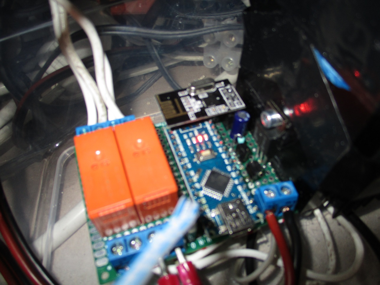
@sundberg84 yes, the picture is a bit vague and messy (it is hard to take a sharp picture above the kitchen lowered-ceiling),
but it gives an impression the big black thing on the right is the heat sink covering the FETs from showing on the image.The T0220 you see is the voltage regulator. The orange blocks are the 230v relays, i did made a 2 way single button version controlling a led-strips (replacing TL-tubes) and a set of 5 LED halogen replacement lamps. The 4 white wires in the left top are connected to my in-wall switches) the lower left wires are connected to the LED's and the lower right wires is the 12 volt power supply. The 3- white/blue wires in the front are connected to a PIR sensor (a little add on to dim the LED when nobody is in the kitchen :-))
-
@sundberg84 yes, the picture is a bit vague and messy (it is hard to take a sharp picture above the kitchen lowered-ceiling),
but it gives an impression the big black thing on the right is the heat sink covering the FETs from showing on the image.The T0220 you see is the voltage regulator. The orange blocks are the 230v relays, i did made a 2 way single button version controlling a led-strips (replacing TL-tubes) and a set of 5 LED halogen replacement lamps. The 4 white wires in the left top are connected to my in-wall switches) the lower left wires are connected to the LED's and the lower right wires is the 12 volt power supply. The 3- white/blue wires in the front are connected to a PIR sensor (a little add on to dim the LED when nobody is in the kitchen :-))
@BartE
Hello, I am happy, to found this sketch, because he has exactly the functions, which I need.
After little issues I have compiled it with Arduino 1.6.7 and Mysensors 1.4.2.
But now always the LEDs are on and the switches are without function. I don't have any home automation controller, only the LED at pin 6 and the switch at pin 4. With other simple sketches the hardware works fine.
My question: It is able to use this sketch without homecontroller or radio (NRF24L01)as stand alone solution only with single buttons?
And if not, which changes I have to do?
Thanks for your help. -
@BartE
Hello, I am happy, to found this sketch, because he has exactly the functions, which I need.
After little issues I have compiled it with Arduino 1.6.7 and Mysensors 1.4.2.
But now always the LEDs are on and the switches are without function. I don't have any home automation controller, only the LED at pin 6 and the switch at pin 4. With other simple sketches the hardware works fine.
My question: It is able to use this sketch without homecontroller or radio (NRF24L01)as stand alone solution only with single buttons?
And if not, which changes I have to do?
Thanks for your help.@Axel yes you can use this sketch stand alone.
In the sketch just:
- remove #include <MySensor.h> and #include <SPI.h>
- remove MyMessage from struct LEDS (6 times on 4 lines)
- remove all lines with "gw." except for gw.wait() replace this function with delay()
- remove the function incomingMessage
That should be it, not sure if all compilers are gone now (did not test it)
And of course there is no needs anymore to add the NFR radio module
-
Hello BartE
Thanks so much for quick replay. I have done your instructions, but now I have a lot of error messages, start with:
Dimmer_net_10:78: error: 'setLedLevel' was not declared in this scopesetLedLevel(id);If I delete all strings, wich make problems, I can compile, but the sketch don´t work.
-
@Axel yes you can use this sketch stand alone.
In the sketch just:
- remove #include <MySensor.h> and #include <SPI.h>
- remove MyMessage from struct LEDS (6 times on 4 lines)
- remove all lines with "gw." except for gw.wait() replace this function with delay()
- remove the function incomingMessage
That should be it, not sure if all compilers are gone now (did not test it)
And of course there is no needs anymore to add the NFR radio module
@BartE said:
@Axel yes you can use this sketch stand alone.
In the sketch just:
- remove #include <MySensor.h> and #include <SPI.h>
- remove MyMessage from struct LEDS (6 times on 4 lines)
- remove all lines with "gw." except for gw.wait() replace this function with delay()
- remove the function incomingMessage
That should be it, not sure if all compilers are gone now (did not test it)
And of course there is no needs anymore to add the NFR radio module
Hello BartE
Could you post the sketch (post 1) for Mysensors2.0.0, please?
Or what I have to change on this sketch to make it's compilated with arduino 1.6.9 Mysensors Library 2.0.02 hours and "Done compiling". So I have wrong library version. And now It's ready to upload. :)
/** * REVISION HISTORY * Version 1.0 - February 15, 2014 - Bruce Lacey * Version 1.1 - August 13, 2014 - Converted to 1.4 (hek) * Version 1.2 - Januari 2016 - Bart Eversdijk * * DESCRIPTION * This sketch provides a Dimmable LED Light using PWM and based on Henrik Ekblad * <henrik.ekblad@gmail.com> Vera Arduino Sensor project. * Developed by Bruce Lacey, inspired by Hek's MySensor's example sketches. * * The circuit uses a MOSFET for Pulse-Wave-Modulation to dim the attached LED or LED strip. * The MOSFET Gate pin is connected to Arduino pin 3 (LED_PIN), the MOSFET Drain pin is connected * to the LED negative terminal and the MOSFET Source pin is connected to ground. * * V1.2 Additions: * control by normal ON/OFF switch * The sketch is now optimized for integration in an existing house wiring situation, Where a standard light switch can be used to control * the dimmer. Just toggling the switch will light the LED-(strip) smooth to 100% level or back to 0% when turning the light off. * By a short ON-OFF switch-pulse the LED will dim to the last set dim level (when it was OFF) or dim to 0% when the LED was on. * Setting a new target dim level can be done by keeping the switch on until it reaches the desired dim-level and the switch OFF again. * Now the LED will stay on keeping the dim level. * In all situations your home automation controller will be informed on the changing situations and off course can override the switch situation * * This sketch controls 2 LED-(strips) but can be easily extended by adding a LEDS entry to the led array (on line 70) * The dim level can be set linear i.s.o. logarithmic (for your eyes this will look more linear) * * http://www.mysensors.org/build/dimmer */ #define MY_RADIO_NRF24 #include <SPI.h> #include <MySensors.h> #include <Bounce2.h> #include <math.h> #define LED1_PIN 6 // Arduino pin attached to MOSFET Gate pin #define SW1_PIN 4 #define LED2_PIN 3 // Arduino pin attached to MOSFET Gate pin #define SW2_PIN 2 #define MYS_INIT_DELAY 500 #define FADE_DELAY 10 // Delay in ms for each percentage fade up/down (10ms = 1s full-range dim) enum DIMCURVES { DIM_LINEAR = 0, // Normal linear curve DIM_LINEAR_INV, // Inverted linear curve DIM_LOGARITHMIC, // Normal logarithmic curve DIM_LOGARITHMIC_INV, // Inverted logarithmic curve DIM_CUSTOM // Define your own dimming curve }; struct LEDS { int currentLevel; // Current dim level int toLevel; // Level to dim to Bounce debouncer; int LedPin; int SwitchPin; byte switchValue; int savedLevel; // level to dim to when on is pressed int switchCount; bool ignoreNextSw; // if true ignore next OFF switch (was overriden by controller in ON state) DIMCURVES dimcurve; // Set the dim curve mode (linear, logarithmic, inverted, custom) MyMessage dimmerMsg; MyMessage lightMsg; }; LEDS led[] = { {0, 0, Bounce(), LED1_PIN, SW1_PIN, 0, 100, 0, false, DIM_LINEAR_INV, MyMessage(0, V_DIMMER), MyMessage(0, V_LIGHT)}, {0, 0, Bounce(), LED2_PIN, SW2_PIN, 0, 100, 0, false, DIM_CUSTOM, MyMessage(1, V_DIMMER), MyMessage(1, V_LIGHT)} }; #define MAXLED (sizeof(led)/sizeof(LEDS)) /*** * Dimmable LED initialization method */ void setup() { // Switch off all leds for (byte id = 0; id < MAXLED; id++) { pinMode(led[id].LedPin, OUTPUT); setLedLevel(id); } // Register the LED Dimmable Light with the gateway for (byte id = 0; id < MAXLED; id++) { pinMode(led[id].SwitchPin, INPUT); // Activate internal pull-up digitalWrite(led[id].SwitchPin, HIGH); present( id, S_DIMMER ); delay( MYS_INIT_DELAY ); // Pull the gateway's current dim level - restore light level upon sendor node power-up request( id, V_DIMMER ); delay( MYS_INIT_DELAY ); // After setting up the button, setup debouncer led[id].debouncer.attach(led[id].SwitchPin); led[id].debouncer.interval(5); } sendSketchInfo("1.2", "LedStripSwitch"); } /*** * Dimmable LED main processing loop */ void loop() { for (byte id = 0; id < MAXLED; id++) { // If target level is not reached fade a little bit more if (led[id].currentLevel != led[id].toLevel) { led[id].currentLevel += ((led[id].toLevel - led[id].currentLevel ) < 0 ? -1 : 1); setLedLevel(id); } // Check debounced button led[id].debouncer.update(); byte switchValue = led[id].debouncer.read() ? 0 : 1; // Inverted signal // Button change detected if (led[id].switchValue != switchValue) { Serial.print (F("Switch ")); Serial.println (switchValue); led[id].switchValue = switchValue; // If key released switch on when off or off when on --> when we where fading (above 100 steps) this is the end state // When we just left the button (> 500) we now turning the lights off again if (!switchValue && !led[id].ignoreNextSw) { if (led[id].switchCount <= 100 || led[id].switchCount > 500) { led[id].toLevel = (led[id].currentLevel ? 0 : led[id].savedLevel); } else { led[id].savedLevel = led[id].toLevel; // Store new saved level } // Inform the gateway of the current DimmableLED's SwitchPower1 and LoadLevelStatus value... send(led[id].lightMsg.set(led[id].toLevel > 0 ? 1 : 0)); send(led[id].dimmerMsg.set(led[id].toLevel) ); } led[id].ignoreNextSw = false; led[id].switchCount = 0; } else if (switchValue && led[id].switchCount <= 500) { // Keep counting until we reached 500 (@ 500 we asume we are in switch ON / OFF mode) led[id].switchCount++; // So this in not just a switch on (or off) but a new target led level key press if (led[id].switchCount > 100) { // Smooth led level increment, until the user found his/here desired dim lever if ((led[id].switchCount % 3) == 0) { // Stop increasing led level @ 100% if (led[id].currentLevel < 100) { if (led[id].currentLevel == 99) { // Inform the gateway we've reached 100% send(led[id].lightMsg.set(1)); send(led[id].dimmerMsg.set(100)); } led[id].currentLevel++; led[id].toLevel = led[id].currentLevel; setLedLevel(id); } } } } } // Wait FADE_DELAY ms to smooth the dim level adjustments wait(FADE_DELAY); } void incomingMessage(const MyMessage &message) { if (message.type == V_LIGHT || message.type == V_DIMMER) { byte id = (message.sensor % MAXLED); // Retrieve the power or dim level from the incoming request message // if this is a V_LIGHT variable update [0 == off, 1 == on] use savedLevel int requestedLevel = ( message.type == V_LIGHT ? led[id].savedLevel * atoi( message.data ) : atoi( message.data ) ); if (requestedLevel > 0) { // Store as lastLevel led[id].savedLevel = requestedLevel; } // Make sure the new level is between 0 - 100 led[id].toLevel = (requestedLevel >= 0 ? min(requestedLevel, 100) : 0); Serial.print(F("Changing node: ")); Serial.print( id ); Serial.print(F(", from: ")); Serial.print( led[id].currentLevel ); Serial.print(F("%, to: ")); Serial.print( requestedLevel ); Serial.println(F("%")); // Inform the gateway of the current DimmableLED's SwitchPower1 and LoadLevelStatus value... send(led[id].lightMsg.set(requestedLevel > 0 ? 1 : 0)); send(led[id].dimmerMsg.set(requestedLevel) ); // Ignore next OFF switch when switch is ON and controller switches LED to OFF state) led[id].ignoreNextSw = (led[id].toLevel == 0 && led[id].SwitchPin); } } void setLedLevel(byte id) { // Convert level 0% - 100% to logathimic OR linear PWM range of 0 to 255 switch (led[id].dimcurve) { case DIM_LINEAR: // Normal linear curve analogWrite(led[id].LedPin, (int)(led[id].currentLevel * 2.5)); break; case DIM_LINEAR_INV: // Inverted linear curve analogWrite(led[id].LedPin, 255 - (int)(led[id].currentLevel * 2.5)); break; case DIM_LOGARITHMIC: // Normal logarithmic curve analogWrite(led[id].LedPin, fscale( 0, 100, 0, 255, led[id].currentLevel, -2)); break; case DIM_LOGARITHMIC_INV: // Inverted logarithmic curve analogWrite(led[id].LedPin, 255 - fscale( 0, 100, 0, 255, led[id].currentLevel, -2)); break; case DIM_CUSTOM: analogWrite(led[id].LedPin, 255 - led[id].currentLevel); break; } } /* fscale Floating Point Autoscale Function V0.1 Paul Badger 2007 Modified from code by Greg Shakar */ float fscale( float originalMin, float originalMax, float newBegin, float newEnd, float inputValue, float curve) { float OriginalRange = 0; float NewRange = 0; float zeroRefCurVal = 0; float normalizedCurVal = 0; float rangedValue = 0; boolean invFlag = 0; // condition curve parameter // limit range if (curve > 10) curve = 10; if (curve < -10) curve = -10; curve = (curve * -.1) ; // - invert and scale - this seems more intuitive - postive numbers give more weight to high end on output curve = pow(10, curve); // convert linear scale into lograthimic exponent for other pow function // Check for out of range inputValues if (inputValue < originalMin) { inputValue = originalMin; } if (inputValue > originalMax) { inputValue = originalMax; } // Zero Refference the values OriginalRange = originalMax - originalMin; if (newEnd > newBegin){ NewRange = newEnd - newBegin; } else { NewRange = newBegin - newEnd; invFlag = 1; } zeroRefCurVal = inputValue - originalMin; normalizedCurVal = zeroRefCurVal / OriginalRange; // normalize to 0 - 1 float // Check for originalMin > originalMax - the math for all other cases i.e. negative numbers seems to work out fine if (originalMin > originalMax ) { return 0; } if (invFlag == 0) { rangedValue = (pow(normalizedCurVal, curve) * NewRange) + newBegin; } else { // invert the ranges rangedValue = newBegin - (pow(normalizedCurVal, curve) * NewRange); } return rangedValue; }``` -
very nice. any chance you have some video up on how it looks coming up?
-
@BartE I was wondering about which relay your using. Am I right to understand that your using 230V to switch a 5v pin? I found a signal relay on the internet is that the type you are using? Do you had a link for better reference I could use? Maybe a link with more information about the relay? I can only find sites that want to sell me a relay but not much information about how it works.
-
@BartE (dutch site.. Even better) thanks for the link. I am looking for the safest way, seeing the this will not be in a quick access location. I want to put it away and only return for update/upgrades. But I will also look into an opto-coupler. Thanks for the tip.:+1:
Hello! It looks like you're interested in this conversation, but you don't have an account yet.
Getting fed up of having to scroll through the same posts each visit? When you register for an account, you'll always come back to exactly where you were before, and choose to be notified of new replies (either via email, or push notification). You'll also be able to save bookmarks and upvote posts to show your appreciation to other community members.
With your input, this post could be even better 💗
Register Login