Skip to content
  • MySensors
  • OpenHardware.io
  • Categories
  • Recent
  • Tags
  • Popular
Skins
  • Light
  • Brite
  • Cerulean
  • Cosmo
  • Flatly
  • Journal
  • Litera
  • Lumen
  • Lux
  • Materia
  • Minty
  • Morph
  • Pulse
  • Sandstone
  • Simplex
  • Sketchy
  • Spacelab
  • United
  • Yeti
  • Zephyr
  • Dark
  • Cyborg
  • Darkly
  • Quartz
  • Slate
  • Solar
  • Superhero
  • Vapor

  • Default (No Skin)
  • No Skin
Collapse
Brand Logo
  1. Home
  2. OpenHardware.io
  3. 💬 In Wall AC/DC Pcb (with Relay) for MySensors (SMD)

💬 In Wall AC/DC Pcb (with Relay) for MySensors (SMD)

Scheduled Pinned Locked Moved OpenHardware.io
switchin-wallrelayacdchlk-pm01
89 Posts 27 Posters 24.2k Views 29 Watching
  • Oldest to Newest
  • Newest to Oldest
  • Most Votes
Reply
  • Reply as topic
Log in to reply
This topic has been deleted. Only users with topic management privileges can see it.
  • gusG Offline
    gusG Offline
    gus
    wrote on last edited by
    #11

    @sundberg84 yes, irl can be tough 😊
    I'll be watching your project, keep up!

    1 Reply Last reply
    1
    • sundberg84S Offline
      sundberg84S Offline
      sundberg84
      Hardware Contributor
      wrote on last edited by sundberg84
      #12

      Everything is moving along slowly... :)

      Today i tested the relay function, the AC - DC (HLK) and if everything fitted inside the 3d box.

      Found some issues with the relay... it opens ok, but I cant close it again so the relay remains open... I need to figure out (or ask) if there is something wrong with my schematics or if the relay I used was bad.

      Also I have to add some mm on the 3dbox in the holes for the relay and HLK.

      0_1470155716207_1.jpg

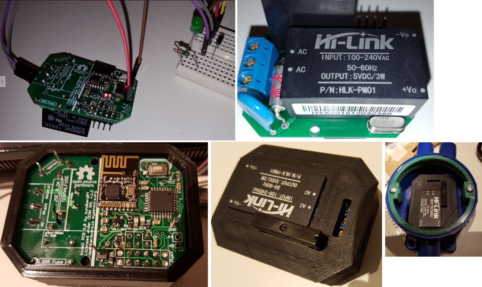
      I have uploaded some images and the eaglesfiles - but I would not recommend to create any pcbs yet - im not satisfied with the result and things will change on the layout and other.

      Controller: Proxmox VM - Home Assistant
      MySensors GW: Arduino Uno - W5100 Ethernet, Gw Shield Nrf24l01+ 2,4Ghz
      MySensors GW: Arduino Uno - Gw Shield RFM69, 433mhz
      RFLink GW - Arduino Mega + RFLink Shield, 433mhz

      1 Reply Last reply
      6
      • sundberg84S Offline
        sundberg84S Offline
        sundberg84
        Hardware Contributor
        wrote on last edited by
        #13

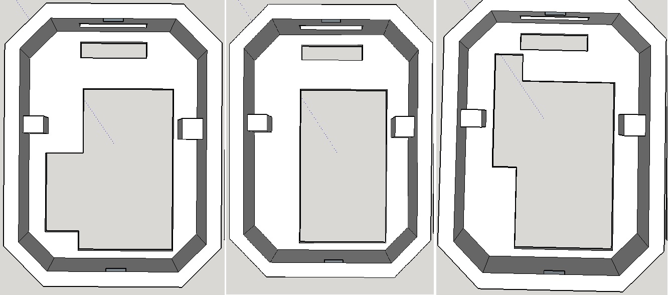
        Updated the 3dbox with some variants...
        From left...
        Box with access to MysX Connector
        Box wthout any access to inside (except AC screw terminal)
        Box with hole for a g3mc-202 relay and no other access.
        0_1471547221319_1.jpg

        Controller: Proxmox VM - Home Assistant
        MySensors GW: Arduino Uno - W5100 Ethernet, Gw Shield Nrf24l01+ 2,4Ghz
        MySensors GW: Arduino Uno - Gw Shield RFM69, 433mhz
        RFLink GW - Arduino Mega + RFLink Shield, 433mhz

        1 Reply Last reply
        5
        • hekH Offline
          hekH Offline
          hek
          Admin
          wrote on last edited by
          #14

          I hope to add a stl 3d viewer soon.. starting to get a grip on three.js :).

          1 Reply Last reply
          4
          • vladimirV Offline
            vladimirV Offline
            vladimir
            wrote on last edited by
            #15

            Hello. Please write size of the device in the box.

            1 Reply Last reply
            0
            • sundberg84S Offline
              sundberg84S Offline
              sundberg84
              Hardware Contributor
              wrote on last edited by
              #16

              @vladimir The PCB is 50x36 cm.

              Controller: Proxmox VM - Home Assistant
              MySensors GW: Arduino Uno - W5100 Ethernet, Gw Shield Nrf24l01+ 2,4Ghz
              MySensors GW: Arduino Uno - Gw Shield RFM69, 433mhz
              RFLink GW - Arduino Mega + RFLink Shield, 433mhz

              1 Reply Last reply
              0
              • vladimirV Offline
                vladimirV Offline
                vladimir
                wrote on last edited by
                #17

                @sundberg84 Please tell me, how you can connect a maximum output devices into an outlet controlled by the relay? As I understand it, it will not sustain even the kettle?
                I apologize in advance for the stupid question, I'm not good at electronics.

                1 Reply Last reply
                0
                • C Offline
                  C Offline
                  Chester
                  wrote on last edited by Chester
                  #18

                  @vladimir , you are correct, in that you can only connect a load that is less than the rating of the relay's, or you can cause damage. Realistically what you would do is use this unit for lighting where the load required can be calculated and won't really change, or if you were using it for a switch, you would need to have some kind of labelling noting that it was only for a maxmium xxxW output.

                  1 Reply Last reply
                  0
                  • sundberg84S Offline
                    sundberg84S Offline
                    sundberg84
                    Hardware Contributor
                    wrote on last edited by sundberg84
                    #19

                    @vladimir - yep, and for protection there is a fuse.
                    Maximum for the G3MC-202PL is 2 A at 100 to 240 VAC

                    Controller: Proxmox VM - Home Assistant
                    MySensors GW: Arduino Uno - W5100 Ethernet, Gw Shield Nrf24l01+ 2,4Ghz
                    MySensors GW: Arduino Uno - Gw Shield RFM69, 433mhz
                    RFLink GW - Arduino Mega + RFLink Shield, 433mhz

                    1 Reply Last reply
                    0
                    • ragflyerR Offline
                      ragflyerR Offline
                      ragflyer
                      wrote on last edited by
                      #20

                      Cool design! Could you post the dimensions including box and relay?
                      I understand one can update firmware through the MYSX connector?

                      sundberg84S 1 Reply Last reply
                      0
                      • ragflyerR ragflyer

                        Cool design! Could you post the dimensions including box and relay?
                        I understand one can update firmware through the MYSX connector?

                        sundberg84S Offline
                        sundberg84S Offline
                        sundberg84
                        Hardware Contributor
                        wrote on last edited by sundberg84
                        #21

                        @ragflyer - Thank you!

                        I suggest using the ISCP to update firmware. There isnt any DTR (to reset) on the MysX (this design - its coming next revision).
                        The box is 56mm wide and 43mm deep and the height is 24.6mm
                        Uncluding the SSR relay sticking out its 29mm height.

                        Controller: Proxmox VM - Home Assistant
                        MySensors GW: Arduino Uno - W5100 Ethernet, Gw Shield Nrf24l01+ 2,4Ghz
                        MySensors GW: Arduino Uno - Gw Shield RFM69, 433mhz
                        RFLink GW - Arduino Mega + RFLink Shield, 433mhz

                        1 Reply Last reply
                        0
                        • fra290F Offline
                          fra290F Offline
                          fra290
                          wrote on last edited by
                          #22

                          Hi sundberg84,
                          what's the status of this great project? can I produce the PCB? I want use this for sopstitute my current X10 plant based on around 20 micro module.
                          only one question, I need to control light also by a traditional switch (momentary button) where a can connect the normal switch, A1 or A2 to GND is OK? in my case can be lot of distance from the node to switch, in some case more them 4 meters and the wire for control switch run in a same pipe to grid linee, can this plant create interference? what do you think to insert one optical cupolaed?
                          Thanks..
                          MArco

                          sundberg84S 1 Reply Last reply
                          0
                          • fra290F fra290

                            Hi sundberg84,
                            what's the status of this great project? can I produce the PCB? I want use this for sopstitute my current X10 plant based on around 20 micro module.
                            only one question, I need to control light also by a traditional switch (momentary button) where a can connect the normal switch, A1 or A2 to GND is OK? in my case can be lot of distance from the node to switch, in some case more them 4 meters and the wire for control switch run in a same pipe to grid linee, can this plant create interference? what do you think to insert one optical cupolaed?
                            Thanks..
                            MArco

                            sundberg84S Offline
                            sundberg84S Offline
                            sundberg84
                            Hardware Contributor
                            wrote on last edited by
                            #23

                            @fra290 - Hi!
                            Status is that I have just received the updated new PCB and are planning to test them... but havent had the time.
                            I have updated openhardware.io with 7.1 which is the latest and the one im testing.

                            You can download the gerber or eagles files and manufacture.
                            I have also made a request for the pcbhouses to add 7.1 so you can buy them from openhardware.io

                            Its small revisions and I dont think there should be any major issues with 7.1

                            Controller: Proxmox VM - Home Assistant
                            MySensors GW: Arduino Uno - W5100 Ethernet, Gw Shield Nrf24l01+ 2,4Ghz
                            MySensors GW: Arduino Uno - Gw Shield RFM69, 433mhz
                            RFLink GW - Arduino Mega + RFLink Shield, 433mhz

                            1 Reply Last reply
                            1
                            • proddyP Offline
                              proddyP Offline
                              proddy
                              wrote on last edited by
                              #24

                              @sundberg84 Thanks for sharing this. I'm gathering the components and plan to build it soon when the PCB v7.1 is available.

                              I do have a few questions if I may

                              • with the Relay, is it important to have one that has zero crossover? E.g the difference between getting the G3MC-202PL over a G3MC-202P
                              • what were you planning to use the 16Mhz oscillator for eventually?
                              • do you see any issues if I build the first prototype using an ESP-12 (ESP8266 with onboard Serial WiFi running at 3.3v)?
                              sundberg84S 1 Reply Last reply
                              0
                              • proddyP proddy

                                @sundberg84 Thanks for sharing this. I'm gathering the components and plan to build it soon when the PCB v7.1 is available.

                                I do have a few questions if I may

                                • with the Relay, is it important to have one that has zero crossover? E.g the difference between getting the G3MC-202PL over a G3MC-202P
                                • what were you planning to use the 16Mhz oscillator for eventually?
                                • do you see any issues if I build the first prototype using an ESP-12 (ESP8266 with onboard Serial WiFi running at 3.3v)?
                                sundberg84S Offline
                                sundberg84S Offline
                                sundberg84
                                Hardware Contributor
                                wrote on last edited by
                                #25

                                @Paul-Derbyshire

                                1. It must depend on what you are planning to connect to the relay
                                2. The oscillator is for the MCU - you can program a bootloader without it and use the internal.
                                3. No issue - please do! Im glad i can make stuff that gets the community forward. Best of luck!

                                Controller: Proxmox VM - Home Assistant
                                MySensors GW: Arduino Uno - W5100 Ethernet, Gw Shield Nrf24l01+ 2,4Ghz
                                MySensors GW: Arduino Uno - Gw Shield RFM69, 433mhz
                                RFLink GW - Arduino Mega + RFLink Shield, 433mhz

                                proddyP 1 Reply Last reply
                                0
                                • sundberg84S sundberg84

                                  @Paul-Derbyshire

                                  1. It must depend on what you are planning to connect to the relay
                                  2. The oscillator is for the MCU - you can program a bootloader without it and use the internal.
                                  3. No issue - please do! Im glad i can make stuff that gets the community forward. Best of luck!
                                  proddyP Offline
                                  proddyP Offline
                                  proddy
                                  wrote on last edited by
                                  #26

                                  @sundberg84 said:

                                  It must depend on what you are planning to connect to the relay

                                  It would use it to switch on and off an external mounted lamp - so with a fixed Watt & Voltage. Probably an LED 220V Lamp. Should I avoid zero-crossover as I've read somewhere that zero-crossover can cause a surge current of perhaps 10 to 40 times the steady state current when switched on.

                                  sundberg84S 1 Reply Last reply
                                  0
                                  • proddyP proddy

                                    @sundberg84 said:

                                    It must depend on what you are planning to connect to the relay

                                    It would use it to switch on and off an external mounted lamp - so with a fixed Watt & Voltage. Probably an LED 220V Lamp. Should I avoid zero-crossover as I've read somewhere that zero-crossover can cause a surge current of perhaps 10 to 40 times the steady state current when switched on.

                                    sundberg84S Offline
                                    sundberg84S Offline
                                    sundberg84
                                    Hardware Contributor
                                    wrote on last edited by
                                    #27

                                    @Paul-Derbyshire - sorry, to be hones i missunderstood you.
                                    Most SSR sold for arduino are P and not PL it seems.

                                    "The light from the diode is beamed into a light-sensitive semiconductor that, in the case of zero-voltage crossover relays, conditions the control circuit to turn on the output solid-state switch at the next zero-voltage crossover. In the case of nonzero-voltage crossover relays, the output solid-state switch is turned on at the precise voltage occurring at the time."

                                    Controller: Proxmox VM - Home Assistant
                                    MySensors GW: Arduino Uno - W5100 Ethernet, Gw Shield Nrf24l01+ 2,4Ghz
                                    MySensors GW: Arduino Uno - Gw Shield RFM69, 433mhz
                                    RFLink GW - Arduino Mega + RFLink Shield, 433mhz

                                    1 Reply Last reply
                                    0
                                    • Jose SimoesJ Offline
                                      Jose SimoesJ Offline
                                      Jose Simoes
                                      wrote on last edited by
                                      #28

                                      hi, just an idea, do you think it is possible to add a current sensor to the PCB in order to add a power meter function to the node to monitor power consumption? say up to 20A

                                      sundberg84S 1 Reply Last reply
                                      0
                                      • Jose SimoesJ Jose Simoes

                                        hi, just an idea, do you think it is possible to add a current sensor to the PCB in order to add a power meter function to the node to monitor power consumption? say up to 20A

                                        sundberg84S Offline
                                        sundberg84S Offline
                                        sundberg84
                                        Hardware Contributor
                                        wrote on last edited by
                                        #29

                                        @Jose-Simoes - no clue about current sensors... sorry I just cant answer that at the moment.

                                        Controller: Proxmox VM - Home Assistant
                                        MySensors GW: Arduino Uno - W5100 Ethernet, Gw Shield Nrf24l01+ 2,4Ghz
                                        MySensors GW: Arduino Uno - Gw Shield RFM69, 433mhz
                                        RFLink GW - Arduino Mega + RFLink Shield, 433mhz

                                        Jose SimoesJ 1 Reply Last reply
                                        0
                                        • Jose SimoesJ Offline
                                          Jose SimoesJ Offline
                                          Jose Simoes
                                          wrote on last edited by
                                          #30
                                          This post is deleted!
                                          1 Reply Last reply
                                          0
                                          Reply
                                          • Reply as topic
                                          Log in to reply
                                          • Oldest to Newest
                                          • Newest to Oldest
                                          • Most Votes


                                          14

                                          Online

                                          11.7k

                                          Users

                                          11.2k

                                          Topics

                                          113.0k

                                          Posts


                                          Copyright 2019 TBD   |   Forum Guidelines   |   Privacy Policy   |   Terms of Service
                                          • Login

                                          • Don't have an account? Register

                                          • Login or register to search.
                                          • First post
                                            Last post
                                          0
                                          • MySensors
                                          • OpenHardware.io
                                          • Categories
                                          • Recent
                                          • Tags
                                          • Popular