im brand new to MySensor and its not going well
-
Hi there, I apologies in advance if the questions I am about to ask here are obvious and I should already have been able to find the answers. But I can’t so here we are.
First of I’m not new to home Automation, I have a Smarthings setup which works very well but its very expensive to expand and I find the configuration a little “home automation for dummies” I have also played around with device.bit but this site appears to have been converted from chines so the language is a little challenging. But it works so if I can’t get the mysensor thing working then I will just go back to that for all its short comings.
So here’s the thing. I have spent many hours now trying to get my first project working with no success.
First of all I have an Arduino mega with a WS5100 Ethernet Shield, an Arduino Nano, 2 x NRF24L01 modules and a relay module.
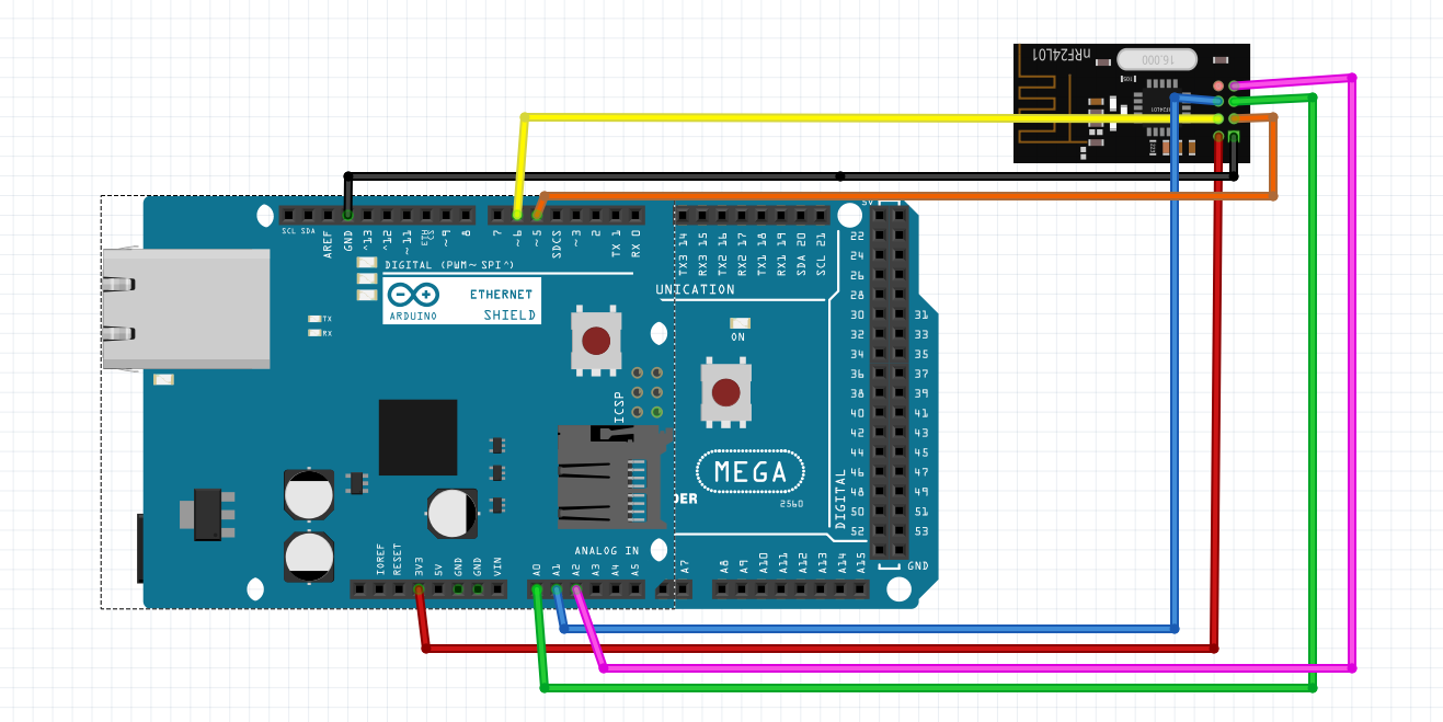
All I am trying to do to start with is connect the Mega and the nano together, the mega is my gateway and the Nano is my Actuator I then want to control the relay using mynodes.net as my controllerSo first this first. Below is the Fritzing sketch of the circuit layout of the Mega
I have loaded the example code from the my sensor library, this is unchanged with the exception of the IP address of cause. Here is where I hit my first issue.
I am using mynodes.net, I really like how it looks so I want to give it a go. I have installed it on my local PC to start with. I will figure out a more permanent solution later. But when I try to connect the mynodes.net to my Arduino it fails. It is just unable to reach the ip address. Doing further digging I discovered that I can not ping the Mega so I decided to do some more fault finding.
I loaded an example from the Arduino Ethernet library called “chat server”, Code is below. The only thing I have changed from default is the ip Address and port. Because this code also asks for gateway dns and subnet, I have also configured them. I loaded it onto the Mega and bingo I was able to connect with mynodes.net without issue. Of cause I could not see any devices because none of that is in the chat server code.#include <SPI.h> #include <Ethernet.h> // Enter a MAC address and IP address for your controller below. // The IP address will be dependent on your local network. // gateway and subnet are optional: byte mac[] = { 0xDE, 0xAD, 0xBE, 0xEF, 0xFE, 0xED }; IPAddress ip(192, 168, 1, 177); IPAddress myDns(192,168,1, 1); IPAddress gateway(192, 168, 1, 1); IPAddress subnet(255, 255, 0, 0); // telnet defaults to port 23 EthernetServer server(5100); boolean alreadyConnected = false; // whether or not the client was connected previously void setup() { // initialize the ethernet device Ethernet.begin(mac, ip, myDns, gateway, subnet); // start listening for clients server.begin(); // Open serial communications and wait for port to open: Serial.begin(9600); while (!Serial) { ; // wait for serial port to connect. Needed for native USB port only } Serial.print("Chat server address:"); Serial.println(Ethernet.localIP()); } void loop() { // wait for a new client: EthernetClient client = server.available(); // when the client sends the first byte, say hello: if (client) { if (!alreadyConnected) { // clear out the input buffer: client.flush(); Serial.println("We have a new client"); client.println("Hello, client!"); alreadyConnected = true; } if (client.available() > 0) { // read the bytes incoming from the client: char thisChar = client.read(); // echo the bytes back to the client: server.write(thisChar); // echo the bytes to the server as well: Serial.write(thisChar); } } }So this has led me to conclude that the GatewayW5100.ino must be relying on some default gateway and possibly subnet configuration that I can’t find. If this is true where do I set it. And also this should be more clearly defined in the initial setup instructions.
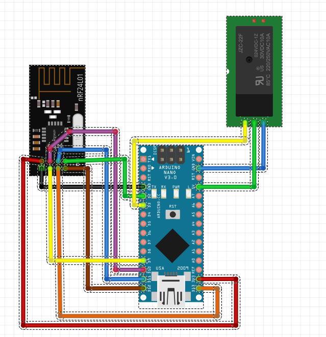
The next step. Below is the Fritzing sketch of the circuit layout of the nano
I have uploaded the default example for a relay Actuator. This loads successfully but when I open the serial window I see the following message, so clearly the two RF24’s are not talking.
0;255;3;0;9;TSM:INIT
0;255;3;0;9;!TSM:RADIO:FAIL
0;255;3;0;9;!TSM:FAILURE
0;255;3;0;9;TSM:PDTNow I have performed a bunch of test on this and I have categorically ruled out any hardware related issues. I did this by following a set of tutorials provided on the following link, https://www.sunfounder.com/learn/Smart-Home-Kit-V2-0-for-Arduino/experiments-smart-home-kit-for-arduino.html the English on this site is pretty average and it took me ages to work out what they were talking about but suffice to say I got it working.
Before I go any deeper, I wonder if there is any detailed instructions on how to setup your first node. This seems to be lacking, for example I have read in a couple of place a reference to addressing the nodes. So I need to understand how to do this? Because its completely unclear how the system works out how to communicate with the different devices, is there some magic involved that I need to configure.
I hope this will be straightforward to answer. I’m not somebody who normally posts in forums I usually figure things out on my own but I think some fundamental how to information is missing somewhere between the getting started and the build my first project. Because I seem to be missing a lot of fundamentals. -
Hi there, I apologies in advance if the questions I am about to ask here are obvious and I should already have been able to find the answers. But I can’t so here we are.
First of I’m not new to home Automation, I have a Smarthings setup which works very well but its very expensive to expand and I find the configuration a little “home automation for dummies” I have also played around with device.bit but this site appears to have been converted from chines so the language is a little challenging. But it works so if I can’t get the mysensor thing working then I will just go back to that for all its short comings.
So here’s the thing. I have spent many hours now trying to get my first project working with no success.
First of all I have an Arduino mega with a WS5100 Ethernet Shield, an Arduino Nano, 2 x NRF24L01 modules and a relay module.
All I am trying to do to start with is connect the Mega and the nano together, the mega is my gateway and the Nano is my Actuator I then want to control the relay using mynodes.net as my controllerSo first this first. Below is the Fritzing sketch of the circuit layout of the Mega
I have loaded the example code from the my sensor library, this is unchanged with the exception of the IP address of cause. Here is where I hit my first issue.
I am using mynodes.net, I really like how it looks so I want to give it a go. I have installed it on my local PC to start with. I will figure out a more permanent solution later. But when I try to connect the mynodes.net to my Arduino it fails. It is just unable to reach the ip address. Doing further digging I discovered that I can not ping the Mega so I decided to do some more fault finding.
I loaded an example from the Arduino Ethernet library called “chat server”, Code is below. The only thing I have changed from default is the ip Address and port. Because this code also asks for gateway dns and subnet, I have also configured them. I loaded it onto the Mega and bingo I was able to connect with mynodes.net without issue. Of cause I could not see any devices because none of that is in the chat server code.#include <SPI.h> #include <Ethernet.h> // Enter a MAC address and IP address for your controller below. // The IP address will be dependent on your local network. // gateway and subnet are optional: byte mac[] = { 0xDE, 0xAD, 0xBE, 0xEF, 0xFE, 0xED }; IPAddress ip(192, 168, 1, 177); IPAddress myDns(192,168,1, 1); IPAddress gateway(192, 168, 1, 1); IPAddress subnet(255, 255, 0, 0); // telnet defaults to port 23 EthernetServer server(5100); boolean alreadyConnected = false; // whether or not the client was connected previously void setup() { // initialize the ethernet device Ethernet.begin(mac, ip, myDns, gateway, subnet); // start listening for clients server.begin(); // Open serial communications and wait for port to open: Serial.begin(9600); while (!Serial) { ; // wait for serial port to connect. Needed for native USB port only } Serial.print("Chat server address:"); Serial.println(Ethernet.localIP()); } void loop() { // wait for a new client: EthernetClient client = server.available(); // when the client sends the first byte, say hello: if (client) { if (!alreadyConnected) { // clear out the input buffer: client.flush(); Serial.println("We have a new client"); client.println("Hello, client!"); alreadyConnected = true; } if (client.available() > 0) { // read the bytes incoming from the client: char thisChar = client.read(); // echo the bytes back to the client: server.write(thisChar); // echo the bytes to the server as well: Serial.write(thisChar); } } }So this has led me to conclude that the GatewayW5100.ino must be relying on some default gateway and possibly subnet configuration that I can’t find. If this is true where do I set it. And also this should be more clearly defined in the initial setup instructions.
The next step. Below is the Fritzing sketch of the circuit layout of the nano
I have uploaded the default example for a relay Actuator. This loads successfully but when I open the serial window I see the following message, so clearly the two RF24’s are not talking.
0;255;3;0;9;TSM:INIT
0;255;3;0;9;!TSM:RADIO:FAIL
0;255;3;0;9;!TSM:FAILURE
0;255;3;0;9;TSM:PDTNow I have performed a bunch of test on this and I have categorically ruled out any hardware related issues. I did this by following a set of tutorials provided on the following link, https://www.sunfounder.com/learn/Smart-Home-Kit-V2-0-for-Arduino/experiments-smart-home-kit-for-arduino.html the English on this site is pretty average and it took me ages to work out what they were talking about but suffice to say I got it working.
Before I go any deeper, I wonder if there is any detailed instructions on how to setup your first node. This seems to be lacking, for example I have read in a couple of place a reference to addressing the nodes. So I need to understand how to do this? Because its completely unclear how the system works out how to communicate with the different devices, is there some magic involved that I need to configure.
I hope this will be straightforward to answer. I’m not somebody who normally posts in forums I usually figure things out on my own but I think some fundamental how to information is missing somewhere between the getting started and the build my first project. Because I seem to be missing a lot of fundamentals.Big welcome to the MySensors community, @Coffeesnob ! And thanks for your feedback. Sorry that things aren't working out for you.
It seems like you have already found the ethernet gateway example. This is a great start for a gateway, but it assumes your home network has a working dhcp server to provide the network interface with ip address and gateway. Most home networks have this, and we want to keep the examples simple to not confuse new users. This is probably what you need:
Enable MY_IP_ADDRESS here if you want a static ip address (no DHCP)
//#define MY_IP_ADDRESS 192,168,178,87

// If using static ip you need to define Gateway and Subnet address as well
#define MY_IP_GATEWAY_ADDRESS 192,168,178,1
#define MY_IP_SUBNET_ADDRESS 255,255,255,0
The getting started guide describes the different concepts in MySensors and how they tie together.
A common problem when using Mega is that the SPI pins are different (as mentioned on connecting the radio).
0;255;3;0;9;!TSM:RADIO:FAIL does not mean that the radios are unable to communicate with eachother. It means that the Arduino is unable to communicate with its radio. My guess is that this is due to the missing SPI settings.Try setting the spi pins (as described on connecting the radio) and see if that helps. If you get stuck, just post here again :)
-
@mfalkvidd thanks very very much for the warm welcome and rapid reply particularly at this time of year. I can see that you have put a huge amount of work into getting this all setup up so you are to be congratulated. However, as a new user coming into this cold with little Arduino knowledge I can see there are some big gaps in the documentation.
First of all, the Ethernet tutorial which is where I started doesn’t say anything at all about DHCP it only says to configure a static IP so that is why I went that direction. But just a point on that. If im not mistaken your code doesn’t show you what the IP address is. This would be extremely useful particularly if you are using MyNode like I am.
In any case, here is what the current status is. I have added a static gateway and Subnet but this didn’t work so there is something else wrong. I have also tried to set to DHCP Mode but according to my Router (Cisco) the device is not getting an IP address. (I have not given full IP and Mac address for security reasons) the mac address is not showing up in the address list.x.x.20.52 ffff.ffff.1ea8 Jan 02 2017 12:18 PM Automatic
x.x.20.55 ffff.ffff.6926 Jan 02 2017 09:32 PM Automatic
x.x.20.59 ffff.ffff.4f1c.d8 Jan 02 2017 07:15 PM Automatic
x.x.20.69 ffff.ffff.30a1.00 Jan 02 2017 09:00 PM Automatic
x.x.20.80 ffff.ffff.5cfb.9e Jan 02 2017 11:07 PM Automatic
x.x.20.86 ffff.ffff.d903.0b Jan 02 2017 09:42 PM Automatic
x.x.20.90 ffff.ffff.3103.ff Jan 02 2017 11:50 AM Automatic
x.x.20.91 ffff.ffff.25fd.9e Jan 02 2017 10:30 PM Automatic
x.x.20.104 ffff.ffff.00f4.2c Jan 02 2017 10:18 PM Automatic
x.x.20.105 ffff.ffff.c58b.f5 Jan 02 2017 09:01 PM Automatic
x.x.20.106 ffff.ffff.1a61.1f Jan 02 2017 11:13 PM Automaticthe full code is below.
/**
 * The MySensors Arduino library handles the wireless radio link and protocol
 * between your home built sensors/actuators and HA controller of choice.
 * The sensors forms a self healing radio network with optional repeaters. Each
 * repeater and gateway builds a routing tables in EEPROM which keeps track of the
 * network topology allowing messages to be routed to nodes.
 *
 * Created by Henrik Ekblad <henrik.ekblad@mysensors.org>
 * Copyright (C) 2013-2015 Sensnology AB
 * Full contributor list: https://github.com/mysensors/Arduino/graphs/contributors
 *
 * Documentation: http://www.mysensors.org
 * Support Forum: http://forum.mysensors.org
 *
 * This program is free software; you can redistribute it and/or
 * modify it under the terms of the GNU General Public License
 * version 2 as published by the Free Software Foundation.
 *
 *******************************
 *
 * REVISION HISTORY
 * Version 1.0 - Henrik EKblad
 * Contribution by a-lurker and Anticimex,
 * Contribution by Norbert Truchsess <norbert.truchsess@t-online.de>
 * Contribution by Tomas Hozza <thozza@gmail.com>
 *
 *
 * DESCRIPTION
 * The EthernetGateway sends data received from sensors to the ethernet link.
 * The gateway also accepts input on ethernet interface, which is then sent out to the radio network.
 *
 * The GW code is designed for Arduino 328p / 16MHz.  ATmega168 does not have enough memory to run this program.
 *
 * LED purposes:
 * - To use the feature, uncomment MY_DEFAULT_xxx_LED_PIN in the sketch below
 * - RX (green) - blink fast on radio message recieved. In inclusion mode will blink fast only on presentation recieved
 * - TX (yellow) - blink fast on radio message transmitted. In inclusion mode will blink slowly
 * - ERR (red) - fast blink on error during transmission error or recieve crc error
 *
 * See http://www.mysensors.org/build/ethernet_gateway for wiring instructions.
 *
 */

// Enable debug prints to serial monitor
#define MY_DEBUG

// Enable and select radio type attached
#define MY_RADIO_NRF24
//#define MY_RADIO_RFM69

// Enable gateway ethernet module type
#define MY_GATEWAY_W5100

// W5100 Ethernet module SPI enable (optional if using a shield/module that manages SPI_EN signal)
#define MY_W5100_SPI_EN 4

// Enable Soft SPI for NRF radio (note different radio wiring is required)
// The W5100 ethernet module seems to have a hard time co-operate with
// radio on the same spi bus.
#if !defined(MY_W5100_SPI_EN) && !defined(ARDUINO_ARCH_SAMD)
#define MY_SOFTSPI
#define MY_SOFT_SPI_SCK_PIN 13
#define MY_SOFT_SPI_MISO_PIN 12
#define MY_SOFT_SPI_MOSI_PIN 11
#endif

// When W5100 is connected we have to move CE/CSN pins for NRF radio
#ifndef MY_RF24_CE_PIN
#define MY_RF24_CE_PIN 5
#endif
#ifndef MY_RF24_CS_PIN
#define MY_RF24_CS_PIN 6
#endif

// Enable to UDP
//#define MY_USE_UDP

//#define MY_IP_ADDRESS 192,168,101,240   // If this is disabled, DHCP is used to retrieve address
//#define MY_IP_GATEWAY_ADDRESS 192,168,101,1
//#define MY_IP_SUBNET_ADDRESS 255,255,255,0
// Renewal period if using DHCP
//#define MY_IP_RENEWAL_INTERVAL 60000
// The port to keep open on node server mode / or port to contact in client mode
#define MY_PORT 5003

// Controller ip address. Enables client mode (default is "server" mode).
// Also enable this if MY_USE_UDP is used and you want sensor data sent somewhere.
//#define MY_CONTROLLER_IP_ADDRESS 192, 168, 178, 254

// The MAC address can be anything you want but should be unique on your network.
// Newer boards have a MAC address printed on the underside of the PCB, which you can (optionally) use.
// Note that most of the Ardunio examples use  "DEAD BEEF FEED" for the MAC address.
#define MY_MAC_ADDRESS 0xDE, 0xAD, 0xBE, 0xEF, 0xFE, 0xED

// Enable inclusion mode
#define MY_INCLUSION_MODE_FEATURE
// Enable Inclusion mode button on gateway
//#define MY_INCLUSION_BUTTON_FEATURE
// Set inclusion mode duration (in seconds)
#define MY_INCLUSION_MODE_DURATION 60
// Digital pin used for inclusion mode button
//#define MY_INCLUSION_MODE_BUTTON_PIN  3

// Set blinking period
#define MY_DEFAULT_LED_BLINK_PERIOD 300

// Flash leds on rx/tx/err
// Uncomment to override default HW configurations
//#define MY_DEFAULT_ERR_LED_PIN 7  // Error led pin
//#define MY_DEFAULT_RX_LED_PIN  8  // Receive led pin
//#define MY_DEFAULT_TX_LED_PIN  9  // Transmit led pin


#if defined(MY_USE_UDP)
#include <EthernetUdp.h>
#endif
#include <Ethernet.h>
#include <MySensors.h>


void setup()
{
}

void loop()
{
}
In relation to the errors, I have done as you have suggested and the NRF24L01+ is connected as per https://www.mysensors.org/build/connect_radio
There does appear to be a bit of confusion if using a W5100 shield module because the Ethernet page talks about issues sharing SPI.
“The W5100 ethernet module has problems sharing SPI with radio. To solve this, we put the radio on a couple of other pins and use so called soft-spi. That's why you have to wire the radio a little differently here than on the usual sensors.”
Can you please clarify if this might apply in my situation.I'm going to keep playing around for about another half hour and see if i can figure out why this isn't working but I would really appreciate your help.
thanks in advance
-
Maybe this thread can help
https://forum.mysensors.org/topic/1245/building-an-ethernet-gateway-on-an-arduino-mega/4 -
@Coffeesnob sorry, I don't now more about this than what I can read in the code and the docs. I don't own a Mega, nor a W5100. Hopefully someone else has a suggestion.
@mfalkvidd Thanks again for your reply, I greatly appreciate your efforts. So, I have made some good progress and now I think we are getting close. I discovered a bit of an anomaly in the way things are described on the website which doesn’t make it easy to understand how to connect things up when your first crack at this. It is probably worthwhile clarifying on this page https://www.mysensors.org/build/ethernet_gateway. So what I have discovered is that the page linked to above describes setting the NRF24L01 on pins A2,A1,SCK,CSN,CE however it also goes on to talk about potential conflicts with SPI, and to use alternative pins, however, it doesn’t really make it very clear how to do that.
So here is what I did. I found a library called NRF24L01_h which was provided to me by Device.bit when I was looking at using their approach. By reading this I was able to get a much clearer understanding of how the SPI works and as you can see this file maps the NRF24L01 pins to 30,28,26,24,22 and 32 as the IRQ.#ifndef NRF24L01_h #define NRF24L01_h #include "API.h" //--------------------------------------------- #define TX_ADR_WIDTH 5 // 5 unsigned chars TX(RX) address width #define TX_PLOAD_WIDTH 1 // 20 unsigned chars TX payload //--------------------------------------------- #define CE 22 // CE_BIT: Digital Input Chip Enable Activates RX or TX mode #define CSN 24 // CSN BIT: Digital Input SPI Chip Select #define SCK_PIN 26 // SCK BIT: Digital Input SPI Clock #define MOSI_PIN 28 // MOSI BIT: Digital Input SPI Slave Data Input #define MISO_PIN 30 // MISO BIT: Digital Output SPI Slave Data Output, with tri-state option #define IRQ 32 // IRQ BIT: Digital Output Maskable interrupt pin //********************************************* #endifSo I started to re-write the example code to user this but in doing so I discovered these lines of code in the example script and then the penny dropped.
#if !defined(MY_W5100_SPI_EN) && !defined(ARDUINO_ARCH_SAMD)
  #define MY_SOFTSPI
  #define MY_SOFT_SPI_SCK_PIN 14
  #define MY_SOFT_SPI_MISO_PIN 16
  #define MY_SOFT_SPI_MOSI_PIN 15
#endif

// When W5100 is connected we have to move CE/CSN pins for NRF radio
#ifndef MY_RF24_CE_PIN
  #define MY_RF24_CE_PIN 5
#endif
#ifndef MY_RF24_CS_PIN
  #define MY_RF24_CS_PIN 6
#endif
0;255;3;0;9;Starting gateway (RNNGA-, 2.0.0)
0;255;3;0;9;TSM:INIT
0;255;3;0;9;TSM:RADIO:OK
0;255;3;0;9;TSM:GW MODE
0;255;3;0;9;TSM:READY
IP: x.x.20.12So we are away. The radio is working and now I am starting to understand how the code works a little better….however!!!!
In the Ethernet code there is a line #define MY_PORT 5003 which is what mynode will connect to. Only issue now is this port doesn’t seem to be open or it is in the wrong mode somewhere deeper in the code. If I load the example code for Chat server. And set the port to 5003 then my node can connect to the Mega no problem. So I know it's not firewall or hardware or in fact network related. Can you point me in the right direction to troubleshoot this please. i suspect the issue will be in one of the libraries further down the line.
Hello! It looks like you're interested in this conversation, but you don't have an account yet.
Getting fed up of having to scroll through the same posts each visit? When you register for an account, you'll always come back to exactly where you were before, and choose to be notified of new replies (either via email, or push notification). You'll also be able to save bookmarks and upvote posts to show your appreciation to other community members.
With your input, this post could be even better 💗
Register Login