Thermostat bridge/HVAC node issues
-
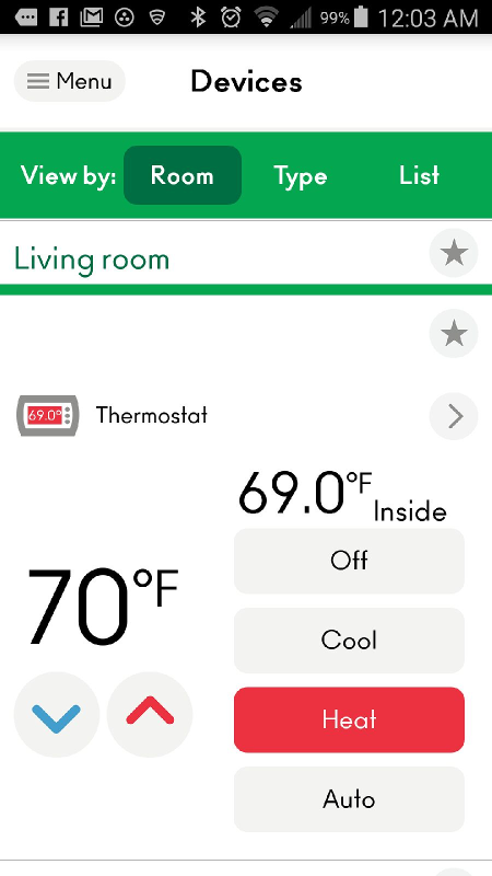
OK, so I have been working on converting my thermostat bridge node to work with Vera. The problem I have is that Vera only shows one set point. As you can see in my screen shot below it shows 0.0 °F for the set point. My thermostat, as well as the MySensors library works with both a heating and cooling set point. It is obvious that the Vera device is not picking up on either of the two set point values, thus the 0.0 °F reading. Also, when ti try to use the controls for raising or lowering the set point, these do not function correctly. How does the Vera plugin first, read the set point value to be displayed, and second, determine which set point it is changing when operating the controls. Because the serial API uses V_HVAC_SETPOINT_COOL and V_HVAC_SETPOINT_HEAT, shouldn't there be controls for both?
The other controls for V_HVAC_FLOW_STATE (thermostat mode control), V_HVAC_FLOW_MODE (fan status control), and displaying the current temperature work fine with my thermostat. My only problem now is the set point controls. -
Not my area but maybe this is some help
https://forum.mysensors.org/topic/3606/redesigned-vera-ui7-thermostat-with-heat-cool-setpoint-hvac-state-fan-status-energy-mode -
Not my area but maybe this is some help
https://forum.mysensors.org/topic/3606/redesigned-vera-ui7-thermostat-with-heat-cool-setpoint-hvac-state-fan-status-energy-mode@rmtucker Thanks for the reply. I did see that link, but I didn't really feel like rewriting my whole thermostat bridge sketch to use that. The sketch that I have currently works for everything except the setpoint. I kind of posed the question if anyone had done a thermostat with MySensors and Vera because the functions of the Vera device that is used when an HVAC node is presented doesn't match or work with the variable types that MySensors 2.0.x has integrated. I am just trying to make it work with what I have. If I could figure out how to change the existing thermostat xml and json files in Vera to just add separate heating and cooling setpoints instead of the single setting that it currently has, that would be ideal. So if anyone has any input on how I could make those changes, I will do it and gladly share the work with the community. Maybe then it could be included as a subfolder in the UI7 interface like the barometer, distance sensor and other specialized MySensors device files.
-
So seeing that I have not gotten much response on this topic other than that mentioned by @rmtucker, and the fact that I was itching for a solution to this, I decided to look more at the solution posted by @mbk .
Right off the bat, I decided to try just uploading the D_HVAC_ZoneThermostatHC1.json and D_HVAC_ZoneThermostatHC1.xml files and changing my Vera thermostat object to point to these instead of the standard thermostat files in the advanced tab. Doing this alone gave me control of both my heating and cooling setpoints as well as my mode and fan options. The "HVAC State" and "Fan Status" sections were obviously blank as I was not in any way sending this information. One option I liked with the original object, though not a huge deal, was the fact that it showed the temp in the icon like this:
With the new object, it just shows empty like this:
Like I say, not a huge deal, but I think with the temp on the icon it looks more professional.
My next step was to upload the new L_Arduino.lua, and I_Arduino1.xml luup files to Vera. Testing after the upload, I did not see any affect on any of my other MySensors node objects, so then all that was needed was tomake the changes to my Thermostat Bridge Node sketch.
First, @mbk suggested a modified MyMessage.h file. I opted not to do that. I simply added these lines at the beginning of my Sketch:
//New sensor type S_HVACHC
const int S_HVACHC = 39;
//New variable types
const int V_HVAC_FAN_STATUS = 51;
const int V_HVAC_MODE_STATE = 52;
const int V_HVAC_ENERGY_MODE = 53;
These gave me all the functionality I needed to use the new luup files. In the sample sketch from @mbk, he has the following:
gw.send(msgSetpointFanStatus.set("On")); // On, Off
gw.send(msgSetpointModeState.set("Idle")); // Off, Heating, Cooling, FanOnly, Idle, Error!
gw.send(msgSetpointEnergyMode.set("Normal")); //EnergySavingsMode, Normal
He mentions the options for msgSetpointFanStatusto be On or Off, though I found through experimentation that you can use any text for these. My HVAC system is a multi stage system. This allowed me to display the corresponding fan stage for msgSetpointFanStatus such as Off, Stage 1, Stage 2, or Stage 3. I could have also used Low, Medium and High. I would imagine I would also be able to use any text for msgSetpointModeState and msgSetpointEnergyMode, though I have not tested this.
Anyways, on to my full sketch. This node is just as it's name implies. It is to bridge the gap between my RCS RS485 serial thermostat network and my MySensors setup. Things have not been 100% tested as of yet, but the majority of the things as far as I can see are working good. I have near full control of my thermostat from Vera now. Here is the full sketch:
/*
  RCS Thermostat for MySensors

  Arduino RCS RS485 thermostat control

  July 7,2016

  This is a gateway bridge to allow an RCS serial thermostat to be accessible to a MySensors
  gateway.  The thermostat being used to test this is an RCS TR40 RS485 thermostat.  The published
  protocol for RCS thermostats can be found at the following address;
  http://www.rcstechnology.com/oldsite/docs/thermostats/serial/SERIAL%20PROTOCOL%20REV%204.3%20%20150-00225-43.pdf

  This sketch features the following:

  Add features here
 */

// Enable debug prints to serial monitor
#define MY_DEBUG

//Set up the nRF24L01+
#define MY_RADIO_NRF24

// Import needed libraries
#include <SPI.h>
#include <MySensors.h>
#include <SoftwareSerial.h>
#include <EEPROM.h>

#define SKETCH_NAME "RCS Thermostat"
#define SKETCH_VERSION "1.0"

/*
#define CHILD_ID_TEMP          0 // V_TEMP
#define CHILD_ID_STATUS        1 // V_STATUS
#define CHILD_ID_SETPOINT_COOL 2 // V_HVAC_SETPOINT_COOL
#define CHILD_ID_SETPOINT_HEAT 3 // V_HVAC_SETPOINT_HEAT
#define CHILD_ID_FLOW_STATE    4 // V_HVAC_FLOW_STATE
#define CHILD_ID_FLOW_MODE     5 // V_HVAC_FLOW_MODE
#define CHILD_ID_HVAC_SPEED    6 // V_HVAC_SPEED
*/

#define CHILD_ID_HVAC        0 // S_HVAC
#define CHILD_ID_OUTSIDE_AIR 2 // S_INFO

// Declare Constants and Pin Numbers
#define SSerialRX            5  //Serial Receive pin 8
#define SSerialTX            3  //Serial Transmit pin 7

#define SSerialTxControl     4  //RS485 Direction control

#define RS485Transmit        HIGH
#define RS485Receive         LOW

#define MY_REPEATER_FEATURE

//New sensor type S_HVACHC
const int S_HVACHC = 39;
//New variable types
const int V_HVAC_FAN_STATUS = 51;
const int V_HVAC_MODE_STATE = 52;
const int V_HVAC_ENERGY_MODE = 53;

// Declare objects
SoftwareSerial RS485Serial(SSerialRX, SSerialTX); // RX, TX

// Sensor values
// V_TEMP, V_STATUS, V_HVAC_FLOW_STATE, V_HVAC_SPEED
// V_HVAC_SETPOINT_COOL, V_HVAC_SETPOINT_HEAT, V_HVAC_FLOW_MODE
MyMessage msgStatus( CHILD_ID_HVAC,               V_STATUS );
MyMessage msgTemp( CHILD_ID_HVAC,                 V_TEMP );
MyMessage msgSetCool( CHILD_ID_HVAC,              V_HVAC_SETPOINT_COOL );
MyMessage msgSetHeat( CHILD_ID_HVAC,              V_HVAC_SETPOINT_HEAT );
MyMessage msgFlowState( CHILD_ID_HVAC,            V_HVAC_FLOW_STATE );
MyMessage msgFlowMode( CHILD_ID_HVAC,             V_HVAC_FLOW_MODE );
MyMessage msgHvacSpeed( CHILD_ID_HVAC,            V_HVAC_SPEED );
MyMessage msgFanStatus( CHILD_ID_HVAC,            V_HVAC_FAN_STATUS );
MyMessage msgModeState( CHILD_ID_HVAC,            V_HVAC_MODE_STATE );
MyMessage msgEnergyMode( CHILD_ID_HVAC,            V_HVAC_ENERGY_MODE );

// This is used to get the outzide air temp to display on the thermostat
MyMessage msgSetOutsideAir( CHILD_ID_OUTSIDE_AIR, V_TEXT );

// DECLARE VARIABLES
//the last sent set point
String setPoint;
//The current mode (O, H, C, A). the initial mode of "-" is to tell the sketch to call for initial status
String mode = "-";
//The last mode received from the thermostat
String LastMode = "";
//The current fan mode received from the thermostat
String FanMode = "";
//The last fan mode received from the thermostat
String LastFanMode = "";
//The last mode received from Vera
String LastVeraMode = "";
//This is the RS485 address of this node that gets sent to the thermostat
String serialAddr = "1";
//The originator code identifier of the originator of the message
String originator = "00";
//Placeholder for the last command sent
String LastSent = "";
//Counter used in place of sleep to request information at certain intervals
int updateCounter = 0;
//The last outside air value received fromVera for display on the WDU
float lastOutsideAir = 0;

/**
 * presentation - Present the parts of the thermostat
 */
void presentation() {

  sendSketchInfo( SKETCH_NAME, SKETCH_VERSION );

  // Register the thermostat with the gateway
  //present( CHILD_ID_HVAC,        S_HVAC );
  present( CHILD_ID_HVAC,        S_HVACHC );
  present( CHILD_ID_OUTSIDE_AIR, S_INFO );

  send(msgSetOutsideAir.setSensor(CHILD_ID_OUTSIDE_AIR).set("-"));

} //End presentation

/**
 * setup - Set up and initialize objects and variables
 */
void setup() {

  Serial.begin(9600);

  // put your setup code here, to run once:
  pinMode( SSerialTxControl, OUTPUT );

  // Initialize RS485 Transceiver
  digitalWrite( SSerialTxControl, RS485Receive );

  // Start the software serial port, to another device
  RS485Serial.begin(9600);   // set the data rate

  //Call for the initial status of the thermostat
  SendCmd("R=1");

} //End setup

/**
 * loop - The main program loop
 */
void loop() {

  String dataIn;

  if (RS485Serial.available()) {
    dataIn = RS485Serial.readStringUntil('\n');
    ParseReceived(dataIn);
  }

  // The updateCounter is used to request information at different intervals. Requesting
  // information at different intervals helps prevent data errors on the serial transmission.
  updateCounter ++;

  // Initiate a status request at 15000 which is one half of the cycle
  if (updateCounter == 10000) {
    SendCmd("R=1");
    request( CHILD_ID_HVAC, V_TEXT );
  }

  // Request the outside air temp from the controller at the second half of the cycle
  if (updateCounter == 20000) {
    SendCmd("R=2");
    request( CHILD_ID_OUTSIDE_AIR, V_TEXT );
    // Reset the counter
    updateCounter = 0;
  }

} //End loop

/**
 * ParseReceived - Used to parse data received from the RS485 network.  Usually the thermostat
 *
 * Attributes:
 * Message  - The message string to parse
 */
void ParseReceived(String Message) {

  String StatusData;
  //int Count;
  String StatusString;
  String Status;
  String Type;
  String Value;

  int Index;
  int Start;
  int End;
  int StatIndex;

  Index = Message.indexOf(' ');
  Start = 0;

  Serial.println("Message: " + Message);

  if (Message.startsWith("A=")) {
    while (End != Message.length()) {
      End = (Index == -1) ? Message.length() : Index;
      //Get the status string to process
      StatusString = Message.substring(Start, End);
      //Change our start position to 1 over the last space found
      Start = Index + 1;
      //Find the end of the next status string
      Index = Message.indexOf(' ', Start);

      //Now we need to process the status string into it's Type and Value
      StatIndex = StatusString.indexOf('=');
      Type = StatusString.substring(0, StatIndex);
      Value = StatusString.substring(StatIndex + 1);
      ParseStatus(Type, Value);
    }
  } else {
    SendCmd(LastSent);
  }

} //End ParseReceived

/**
 * ParseStatus - Used to parse a status parameter sent from the thermostat
 *
 * Attributes:
 * type  - The status type
 * Value - The status value
 */
void ParseStatus(String Type, String Value) {

  if (Type == "OA") {
    //Outside Air not used
  } else if (Type == "Z") {
    //Zone not used
  } else if (Type == "T") {
    //Current temperature
    send(msgTemp.set( Value.toFloat(), 1 ));
  } else if (Type == "SP") {
    //Set Point (for single setpoint systems)
    if (mode == "H" || mode == "EH") {
      send(msgSetHeat.set( Value.toFloat(), 1 ));
    } else if (mode == "C") {
      send(msgSetCool.set( Value.toFloat(), 1 ));
    }
  } else if (Type == "SPH") {
    //Heating set point
    send(msgSetHeat.set( Value.toFloat(), 1 ));
  } else if (Type == "SPC") {
    //Cooling set point
    send(msgSetCool.set( Value.toFloat(), 1 ));
  } else if (Type == "M") {
    //RCS thermostat mode (MySensors V_HVAC_FLOW_STATE)
    mode = Value.c_str();
    Serial.println("mode=" + mode);
    send(msgEnergyMode.set("Normal"));
    if (LastMode != mode) {
      if (mode == "O") {
          send(msgFlowState.set("Off"));
          send(msgModeState.set("Off"));
      } else if (mode == "H") {
         send(msgFlowState.set("HeatOn"));
          send(msgModeState.set("Heating"));
      } else if (mode == "C") {
          send(msgFlowState.set("CoolOn"));
          send(msgModeState.set("Cooling"));
      } else if (mode == "A") {
          send(msgFlowState.set("AutoChangeOver"));
      } else if (mode == "EH") {
          send(msgFlowState.set("HeatOn"));
          send(msgModeState.set("Heating"));
      }
      LastMode = mode;
    }
  } else if (Type == "FM") {
    //RCS fan mode (MySensors V_STATUS 0=off 1=on)
    FanMode = Value.c_str();
    if (LastFanMode != FanMode) {
      if (FanMode == "1") {
        send(msgFlowMode.set("ContinuousOn"));
      } else {
        send(msgFlowMode.set("Auto"));
      }
      LastFanMode = FanMode;
    }
  //Type 2 status message types
  } else if (Type == "H1A" && Value == "1") {
    //RCS heating stage 1
    send(msgHvacSpeed.set("Min"));
    send(msgFanStatus.set("Stage 1"));
  } else if (Type == "H2A" && Value == "1") {
    //RCS heating stage 2
    send(msgHvacSpeed.set("Normal"));
    send(msgFanStatus.set("Stage 2"));
  } else if (Type == "H3A" && Value == "1") {
    //RCS heating stage 3
    send(msgHvacSpeed.set("Max"));
    send(msgFanStatus.set("Stage 3"));
  } else if (Type == "C1A" && Value == "1") {
    //RCS cooling stage 1
    send(msgHvacSpeed.set("Normal"));
    send(msgFanStatus.set("Stage 1"));
  } else if (Type == "C2A" && Value == "1") {
    //RCS cooling stage 2
     send(msgHvacSpeed.set("Max"));
    send(msgFanStatus.set("Stage 2"));
  // We may receive values of 0 for both C1A and H1A we may get an on/Auto cycling if one or the
  // other is on. To prevent this we must verify the mode we are in and only set it to auto if
  // the heating or cooling stage with a 0 value matches the mode we are in
  } else if (((Type == "C1A" && mode == "C") || (Type == "H1A" && (mode == "H" || mode == "EH"))) && Value == "0") {
    send(msgFanStatus.set("Off"));
  } else if (Type == "FA") {
    //RCS fan status (MySensors V_HVAC_FLOW_MODE)
    if (Value == "1") {
      send(msgFlowMode.set("ContinuousOn"));
    } else {
      send(msgHvacSpeed.set("Auto"));
    }
  } else if (Type == "VA") {
    //Vent damper not used
  } else if (Type == "D1") {
    //Damper #1 not used
  } else if (Type == "SCP") {
    //This is for MOT (Minimum Off Time) and MRT (Minimum Run Time) statuses for
    //stages 1 and 2.  I may find a way to implement this into Vera, but for now
    //it is not used

    //String stg1 = Value.substring(0, 1);
    //String stg2 = Value.substring(0, Value.length() - 1);
  }

} //End ParseStatus

/**
 * SendCmd - Sends a command out to the RS485 network
 *
 * Attributes:
 * cmd - The command to send
 */
void SendCmd(String cmd) {

  //Assemble the command string using the defined serial address and originator codes
  String commandStr = "A=" + serialAddr + " O=" + originator + " " + cmd;
  // Enable RS485 Transmit only for the duration of the send
  digitalWrite(SSerialTxControl, RS485Transmit);
  RS485Serial.print(commandStr + "\r");
  LastSent = cmd;
  //Return to RS485 receive mode
  digitalWrite(SSerialTxControl, RS485Receive);
  delay(50);

} //End SendCmd

/**
 * receive - Process the incoming messages and watch for an incoming boolean 1
 *           to toggle the garage door opener.
 *
 * Attributes:
 * MyMessage - The referenced message object received
 */
void receive(const MyMessage &message) {

  //Check messages from controller
  if ( message.type == V_TEXT ) {
    float OT;
    String temp;

    OT = atof(message.data);
    temp = String( OT, 0 );
    if (lastOutsideAir != OT) {
      SendCmd("OT=" + temp);
    }
    lastOutsideAir = OT;
  } //End V_TEXT

  if (message.type == V_TEMP) {
    //Get the temp setting passed
    setPoint = String(atof(message.data), 0);
    if (mode == "H" || mode == "EH") {
      SendCmd("SPH=" + setPoint + " R=1");
    } else if (mode == "C") {
      SendCmd("SPC=" + setPoint + " R=1");
    }
  } //End V_TEMP

  if ( message.type == V_STATUS ) {
    String M = message.data;
    SendCmd("F=" + M + " R=1");
  } //End V_STATUS

  if ( message.type == V_HVAC_FLOW_STATE ) {
    String M = message.data;
    send(msgEnergyMode.set("Normal"));
    if (M == "Off") {
      mode = "O";
      SendCmd("M=O R=1");
      send(msgModeState.set("Off"));
    } else if (M == "HeatOn") {
      mode = "H";
      SendCmd("M=H R=1");
      send(msgModeState.set("Heating"));
    } else if (M == "CoolOn") {
      mode = "C";
      SendCmd("M=C R=1");
      send(msgModeState.set("Cooling"));
    } else if (M == "AutoChangeOver") {
      mode = "A";
      SendCmd("M=A R=1");
    }
  } //End V_HVAC_FLOW_STATE

  if ( message.type == V_HVAC_SPEED ) {
    //Serial.println("Speed: " + String(message.data));
  } //End V_HVAC_SPEED

  if (message.type == V_HVAC_SETPOINT_COOL) {
     setPoint = String(atof(message.data), 0);
     SendCmd("SPC=" + setPoint + " R=1");
  } //End V_HVAC_SETPOINT_COOL

  if (message.type == V_HVAC_SETPOINT_HEAT) {
     setPoint = String(atof(message.data), 0);
     SendCmd("SPH=" + setPoint + " R=1");
  } //End V_HVAC_SETPOINT_HEAT

  if ( (message.type == V_HVAC_FLOW_MODE) ) {
    String SM = message.data;
    if (SM == "Auto") {
      SendCmd("F=0 R=1");
    } else if (SM == "ContinuousOn" || SM == "PeriodicOn") {
      SendCmd("F=1 R=1");
    }
  } //End V_HVAC_FLOW_MODE
} //End receive
I think that this information should be put into the next release of MySensors. Though I don't think we necessarily need a fully new sensor type such as S_HVACHC, the HVAC_FAN_STATUS, V_HVAC_MODE_STATE, and V_HVAC_ENERGY_MODE variable types could be added to work with the S_HVAC sensor type.
If anyone has any questions, comments or criticisms, feel free to post here.
Happy New Year to all
-
So another update on all of this:
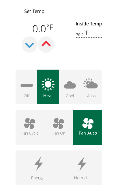
So I set up @mbk's D_HVAC_ZoneThermostatHC1.xml and D_HVAC_ZoneThermostatHC1.json files for controlling heating and cooling setpoints. As far as control from within Vera this works. I can both see and set the setpoint, which for now is heating, but I can set both. However, as mentioned in my previous post, I cannot see the temp displayed in the thermostat icon.
My issue now is that I am beta testing the Amazon Echo alexa skill which is supposed to be able to control my thermostat. So if I am running @mbk's xml and json files and I say "Alexa, set thermostat to 70 degrees", Alexa responds with "Setting living room thermostat to 70". If I then go and check my thermostat, it does not have the temp set. HOWEVER, if I change back to using the standard D_HVAC_ZoneThermostat1.xml and D_HVAC_ZoneThermostat1.json files and issue the same command to the Echo, "Alexa, set thermostat to 70 degrees", Alexa again responds with "Setting living room thermostat to 70", and when I go and check the thermostat, it has correctly set the heating setpoint to 70. Just to double check, I had Alexa set it to 65 degrees, and the thermostat responded perfectly.
SO, to sum up, I have @mbk's files which give me the screenshot below:
PROS:- I can see and control both the heating and cooling setpoints
- It shows me the current HVAC state and fan status
CONS:
- I don't get the temp in the thermostat icon which is used by the Android app to show the current temp.
- I cannot use this with the Alexa skills beta to allow me voice control.
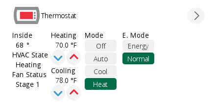
AND, with the default files which give me this:
PROS:- I can see the temp displayed in the icon allowing it to display correctly in the Android app
- Works with the Alexa skill for voice control
CONS:
- I cannot see the current setpoint value for the selected mode ( heating or cooling)
- I cannot change the setpoint from within Vera
- The temp shown in the icon shows to 1 decimal place and I only need to the whole number. With 1 decimal place, the degree symbol at the end gets cut off slightly.
I would really like to find a happy medium between the two configurations. I want to have my control with Alexa as well as within Vera. I would like to be able to see the HVAC State and current Fan Status. I would like the icon to show the temp as a whole number so I can see it in my Android app. To get all of this, it seems like it would be easier to make the changes within @mbk's files, but I have been trying for a couple days now and can't figure things out. I am open for any input on this topic.
-
So through some trial and error, I have made some progress on this. I don't have things 100% the way I would want them, but I have the basics working for now. I was able to get the setpoint working on the default display. It took some tweaking of the L_Arduino.lua file to do it.
What I figured out is that the D_HVAC_ZoneThermostat1.xml and D_HVAC_ZoneThermostat1.json files were most likely designed for thermostats that work off of a single setpoint value, and internally determine whether that value needs to be a heating or cooling setpoint. I would assume that it would be determined based off of the current mode (Heat or Cool). In the L_Arduino.lua file for MySensors stuff, there is only 2 setpoint serviceIds, urn:upnp-org:serviceId:TemperatureSetpoint1_Heat or urn:upnp-org:serviceId:TemperatureSetpoint1_Cool. What was needed was a single non-biased setpoint serviceId urn:upnp-org:serviceId:TemperatureSetpoint1. I knew that I was going to have to deal with that value being passed both from and to the node. As for the values coming from the node, I modified the "setVariableIfChanged" function and added the following lines:
	if ((serviceId == "urn:upnp-org:serviceId:TemperatureSetpoint1_Heat") or (serviceId == "urn:upnp-org:serviceId:TemperatureSetpoint1_Cool")) then
		luup.variable_set("urn:upnp-org:serviceId:TemperatureSetpoint1", name, value, deviceId)
	end
The new function looks like this:
--
-- Update variable if changed
-- Return true if changed or false if no change
--
function setVariableIfChanged(serviceId, name, value, deviceId)
    log(serviceId ..","..name..", "..value..", ".. deviceId)
    local curValue = luup.variable_get(serviceId, name, deviceId)

    if ((value ~= curValue) or (curValue == nil) or (serviceId == "urn:micasaverde-com:serviceId:SceneController1")) then
        luup.variable_set(serviceId, name, value, deviceId)
	if ((serviceId == "urn:upnp-org:serviceId:TemperatureSetpoint1_Heat") or (serviceId == "urn:upnp-org:serviceId:TemperatureSetpoint1_Cool")) then
		luup.variable_set("urn:upnp-org:serviceId:TemperatureSetpoint1", name, value, deviceId)
	end
	return true

    else
        return false

    end
end
Then, for the outgoing side of things to send the new setpoint value to the node when changed from Vera I have added the following line to both the SetpointHeat and SetpointCool functions:
sendCommand(luup.devices[device].id,"HVAC_SETPOINT",NewCurrentSetpoint)The new functions look like this:
-- Heater commands
function SetpointHeat(device, NewCurrentSetpoint)
	sendCommand(luup.devices[device].id,"HVAC_SETPOINT_HEAT",NewCurrentSetpoint)
	sendCommand(luup.devices[device].id,"HVAC_SETPOINT",NewCurrentSetpoint)
	luup.log("New Current SetPoint Heat " .. NewCurrentSetpoint)
end

function SetpointCool(device, NewCurrentSetpoint)
	sendCommand(luup.devices[device].id,"HVAC_SETPOINT_COOL",NewCurrentSetpoint)
	sendCommand(luup.devices[device].id,"HVAC_SETPOINT",NewCurrentSetpoint)
	luup.log("New Current SetPoint Cool " .. NewCurrentSetpoint)
end
The last thing was to add the new variable type to both the L_Arduino.lua file and to my sketch for my node. On the lua side I added this to the tVarTypes array:
HVAC_SETPOINT = {54, "urn:upnp-org:serviceId:TemperatureSetpoint1", "CurrentSetpoint", "" }This required a corresponding V_HVAC_SETPOINT variable type in the sketch:
const int V_HVAC_SETPOINT = 54;I had then added this to my receive function in the sketch:
 if (message.type == V_HVAC_SETPOINT) {
     setPoint = String(atof(message.data), 0);
     SendCmd("SP=" + setPoint + " R=1");
  } //End V_HVAC_SETPOINT
Since my thermostat has a single setpoint option that makes the determination whether it should be a heating or cooling setpoint, I didn't have to worry about making that determination in my sketch.
I can now see and control my thermostat setpoint within Vera, and also set the thermostat using my Amazon Echo. My suggestion would be to add the new variable types found in my sketch as standards within MySensors for use with S_HVAC. The changes to the L_Arduino.lua file, or a suitable variation of that, should also be made standard.
-
I found one more change that I had to make. I noticed that sometimes, the cooling setpoint was being displayed when the furnace was in HeatOn mode. To fix this, I had to check the setpoint value passed against the current mode that the thermostat is in. This is in the setVariableIfChanged function of the L_Arduino.lua file. Here is the modified function:
--
-- Update variable if changed
-- Return true if changed or false if no change
--
function setVariableIfChanged(serviceId, name, value, deviceId)
    log(serviceId ..","..name..", "..value..", ".. deviceId)
    local curValue = luup.variable_get(serviceId, name, deviceId)
    local SPH = "urn:upnp-org:serviceId:TemperatureSetpoint1_Heat"
    local SPC = "urn:upnp-org:serviceId:TemperatureSetpoint1_Cool"
    local modeStatus = luup.variable_get("urn:upnp-org:serviceId:HVAC_UserOperatingMode1","ModeStatus", deviceId)

    if ((value ~= curValue) or (curValue == nil) or (serviceId == "urn:micasaverde-com:serviceId:SceneController1")) then
        luup.variable_set(serviceId, name, value, deviceId)
	-- Here we check if a heating or cooling setpoint was passed and ONLY set the TemperatureSetpoint if we are in the
	-- corresponding mode.  So if the setpoint is for heating and the mode is HeatOn we'll set it, but if it is for
	-- cooling and the mode is HeatOn we won't.  This is to ensure that the correct setpoint is displayed.
	if (((serviceId == SPH) and (modeStatus == "HeatOn") or ((serviceId == SPC) and (modeStatus == "CoolOn")))) then
		luup.variable_set("urn:upnp-org:serviceId:TemperatureSetpoint1", name, value, deviceId)
	end
	return true

    else
        return false

    end
end
I would assume the following line should work for any thermostat when there is more than one thermostat in a system.
local modeStatus = luup.variable_get("urn:upnp-org:serviceId:HVAC_UserOperatingMode1","ModeStatus", deviceId)This should get the corresponding mode of the thermostat for which the setpoint is being sent based on the deviceId.
-
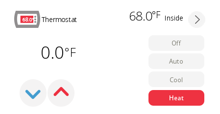
So the plot thickens with this. I was testing things with the mobile app the other day and the mobile app for some reason was displaying the cooling setpoint above the arrow controls. When I tried changing it, it was then changing the heating setpoint to the cooling setpoint value. I took a screenshot of my phone, but unfortunately I did not get a copy of what was happening in the logs at that time. I have been ill for a few days, but decided I would revisit this so I could put together this post. When I checked my phone again, it is now displaying the heating setpoint as the control. I am a bit baffled.
Here is the screenshot from a few days ago:
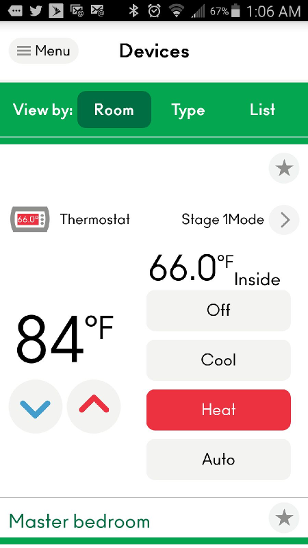
And here is the screenshot from today:
I am going to keep my eye on this over the next few days and see what happens. Regardless, I think a solution to this on the MySensors end would be to add a V_HVAC_SETPOINT variable to be used as as an alternative to the V_HVAC_SETPOINT_COOL and V_HVAC_SETPOINT_HEAT variables for cases like this. The logic for changing the heating or cooling setpoint can then be dealt with on the MySensors node sketch end.
-
Hi @dbemowsk,
Have you considered creating a GitHub Pull request for the Vera plugin for your modifications?@korttoma Hadn't thought about it. I'll look at cleaning it up in the next couple weeks and doing a pull request. I appreciate the thought.
Vera Plus running UI7 with MySensors, Sonoffs and 1-Wire devices
Visit my website for more Bits, Bytes and Ramblings from me: http://dan.bemowski.info/ -
@korttoma Hadn't thought about it. I'll look at cleaning it up in the next couple weeks and doing a pull request. I appreciate the thought.
@dbemowsk sorry for resurrecting this old thread. I'm facing the same issues with the hvac controls (I just want to control my AC stuff using the "stock" HVAC controls).
I'm about to add your code to my local install, do you mind if I try to collect everything and I create a pull request for the mainline?
I'm just asking because I haven't seen any pull requests in the main tree and I suppose you've been busy.Thanks for the good work you've done in debugging the issue :-)
-
Here's the pull request, up for review: https://github.com/mysensors/Vera/pull/59


Hello! It looks like you're interested in this conversation, but you don't have an account yet.
Getting fed up of having to scroll through the same posts each visit? When you register for an account, you'll always come back to exactly where you were before, and choose to be notified of new replies (either via email, or push notification). You'll also be able to save bookmarks and upvote posts to show your appreciation to other community members.
With your input, this post could be even better 💗
Register Login