Skip to content
  • MySensors
  • OpenHardware.io
  • Categories
  • Recent
  • Tags
  • Popular
Skins
  • Light
  • Brite
  • Cerulean
  • Cosmo
  • Flatly
  • Journal
  • Litera
  • Lumen
  • Lux
  • Materia
  • Minty
  • Morph
  • Pulse
  • Sandstone
  • Simplex
  • Sketchy
  • Spacelab
  • United
  • Yeti
  • Zephyr
  • Dark
  • Cyborg
  • Darkly
  • Quartz
  • Slate
  • Solar
  • Superhero
  • Vapor

  • Default (No Skin)
  • No Skin
Collapse
Brand Logo
  1. Home
  2. Announcements
  3. 💬 Battery Powered Sensors

💬 Battery Powered Sensors

Scheduled Pinned Locked Moved Announcements
battery
347 Posts 55 Posters 67.0k Views 53 Watching
  • Oldest to Newest
  • Newest to Oldest
  • Most Votes
Reply
  • Reply as topic
Log in to reply
This topic has been deleted. Only users with topic management privileges can see it.
  • Moebius LutchingM Offline
    Moebius LutchingM Offline
    Moebius Lutching
    wrote on last edited by
    #54

    I'm building my home automation with a few Whisper Nodes (https://talk2.wisen.com.au/product-talk2-whisper-node-avr/) and I just got them working with the MySensor code. I'm running most of my projects with two AA but I just setup one with a CR2032 transmitting my attic temperature every 5 minutes to see how it goes. One thing I discovered is that the board comes two "built-in" resistor divider to monitor the battery and power supply voltage, which is pretty handy... also they have added a Mosfet on the battery voltage divider, I guess to eliminate the constant current leak consumed by the voltage divider, am I right?! (https://bitbucket.org/talk2/whisper-node-avr/overview#markdown-header-voltage-monitor)

    1 Reply Last reply
    0
    • bjacobtB bjacobt

      Hi,
      I'm sorry what do you mean by "control your resistance value"

      this is my circuit,

      1M resistor to +V rail, 470K resistor to GND and middle point to A0.
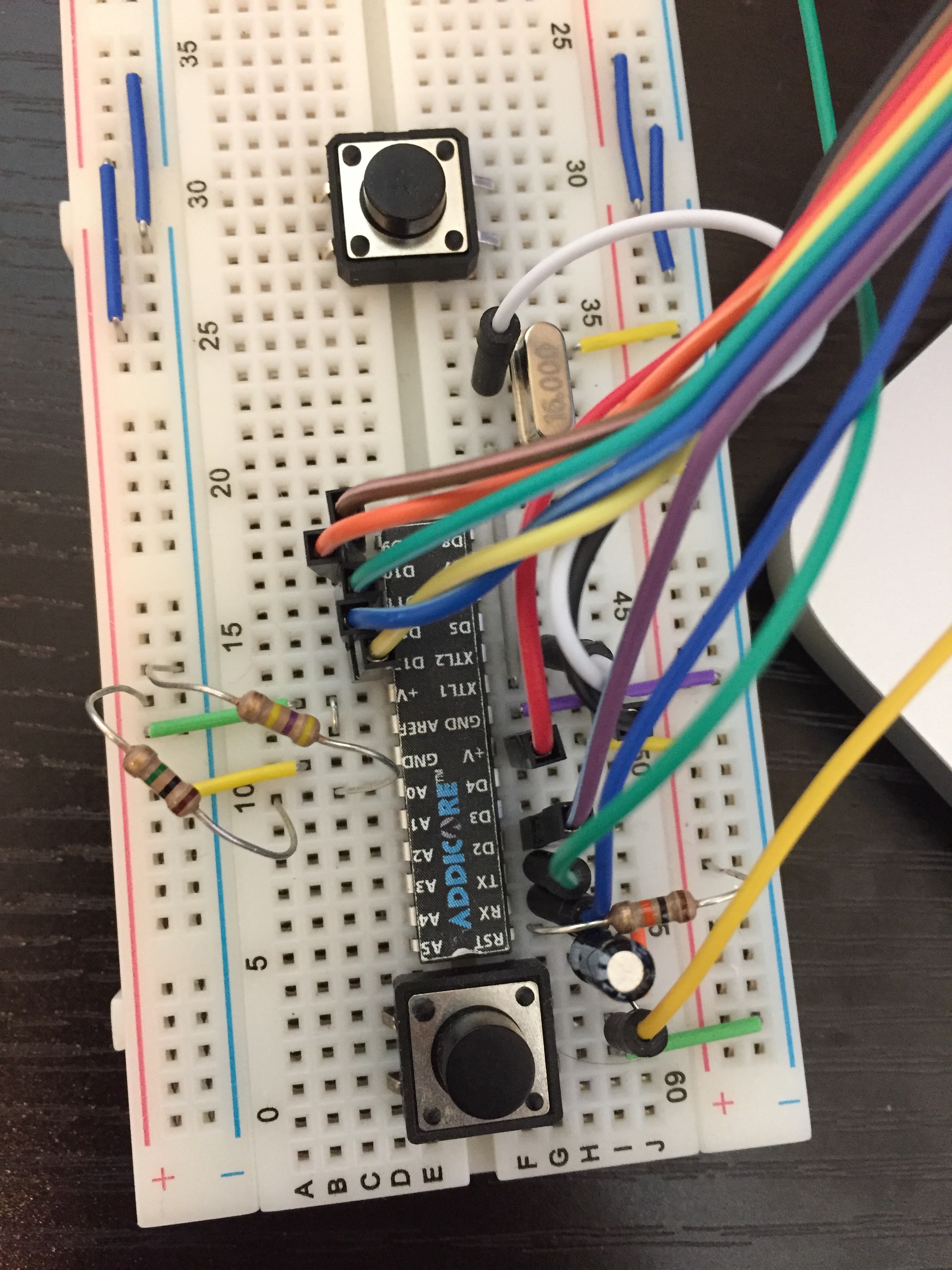
      0_1478097209731_IMG_1543.JPG ,

      GertSandersG Offline
      GertSandersG Offline
      GertSanders
      Hardware Contributor
      wrote on last edited by
      #55

      @bjacobt

      It seems you are missing the capacitors connecting each side of the crystal to ground. Those should be between 15 and 25pf (depends on the crystal), normally ceramic type.

      1 Reply Last reply
      0
      • GertSandersG GertSanders

        Here is a view of a node running exactly 1year. The effect of a bad radio is seen here as the fast voltage drops. I had a very low charged battery to start with, replaced it with new batteries which also discharged fast, and replaced both batteries and the radio. Since mid january 2016 the node has been running as expected. My guess is that this combo will run for 2 years (given how it has been working the past 9 months).

        This node measures battery voltage, temperature and humidity and sends 3 messages about every 5 minutes.

        0_1474202873202_Screen Shot 2016-09-18 at 14.41.30.png

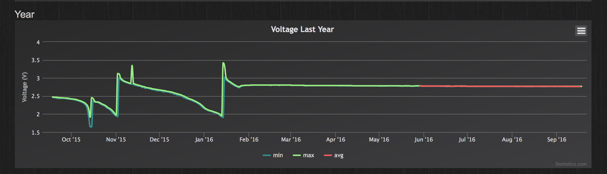
        And here is the battery measurement of the second node that went "online" the same day (18/sep/2015, with a good radio, and similarly used batteries from the start). This node sends very few messages (at least 1 every 24 hours, and when one of 3 contacts are opened). Most days it just sends 1 message.

        0_1474203476121_Screen Shot 2016-09-18 at 14.55.05.png

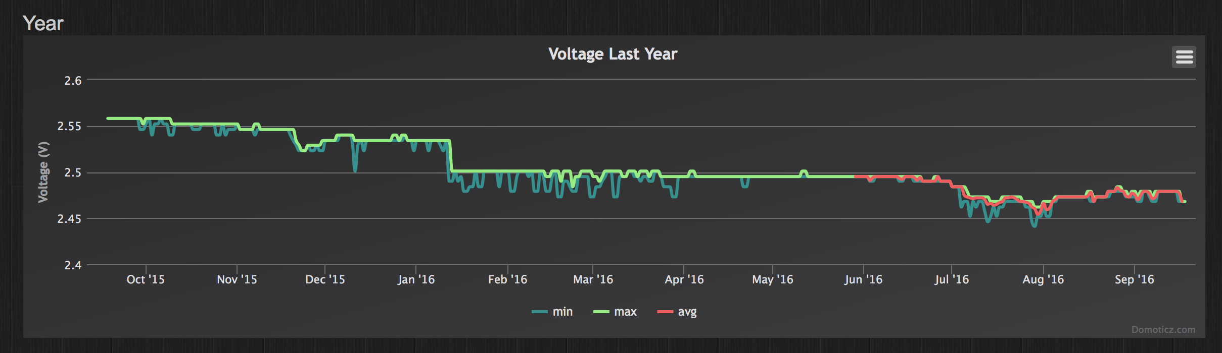
        So even with batteries already at a low level, you can make useful nodes using the MySensors setup :-)

        C Offline
        C Offline
        chaeron
        wrote on last edited by
        #56

        @GertSanders

        How are you sending the voltage?

        Sensor = S_MULTIMETER and value = V_VOLTAGE in a normal message?

        Thx!

        GertSandersG 1 Reply Last reply
        0
        • C chaeron

          @GertSanders

          How are you sending the voltage?

          Sensor = S_MULTIMETER and value = V_VOLTAGE in a normal message?

          Thx!

          GertSandersG Offline
          GertSandersG Offline
          GertSanders
          Hardware Contributor
          wrote on last edited by
          #57

          @chaeron
          Correct :-)

          C 1 Reply Last reply
          0
          • GertSandersG GertSanders

            @chaeron
            Correct :-)

            C Offline
            C Offline
            chaeron
            wrote on last edited by
            #58

            @GertSanders

            Thanks! I'll use that approach for all my house sensors, since right now all I send is battery percentage..

            ...at least until/if they add support for a I_Battery_Voltage internal value. 😈

            1 Reply Last reply
            0
            • meanmrgreenM Offline
              meanmrgreenM Offline
              meanmrgreen
              wrote on last edited by
              #59

              Realy n00b in electronics here but do you need to use those exact values of the resistors when hooking this up?

              mfalkviddM 1 Reply Last reply
              0
              • meanmrgreenM meanmrgreen

                Realy n00b in electronics here but do you need to use those exact values of the resistors when hooking this up?

                mfalkviddM Offline
                mfalkviddM Offline
                mfalkvidd
                Mod
                wrote on last edited by mfalkvidd
                #60

                @meanmrgreen are you reffering to the 470K+1M resistors? (This is a long thread)
                If so, they can be any size but the code will need to be adjusted if the ratio between the resistors is changed.

                Also, less resistance will drain the battery faster.

                1 Reply Last reply
                0
                • meanmrgreenM Offline
                  meanmrgreenM Offline
                  meanmrgreen
                  wrote on last edited by
                  #61

                  Yes i do.
                  This is like going back to school... but fun!

                  1 Reply Last reply
                  1
                  • G Offline
                    G Offline
                    giovaFr
                    wrote on last edited by
                    #62

                    can someone explains why using analogReference(INTERNAL) ?

                    for the moment i only have 5V nano suplyed by a 7.4V lipo (i know, this is not a good choice, but i just have this right now) so with that hardware, 1.1V seems too low.
                    I mean that resistance ratio to reach 1.1V max smells a very inacurate result; isn't it?

                    tonnerre33T 1 Reply Last reply
                    0
                    • G giovaFr

                      can someone explains why using analogReference(INTERNAL) ?

                      for the moment i only have 5V nano suplyed by a 7.4V lipo (i know, this is not a good choice, but i just have this right now) so with that hardware, 1.1V seems too low.
                      I mean that resistance ratio to reach 1.1V max smells a very inacurate result; isn't it?

                      tonnerre33T Offline
                      tonnerre33T Offline
                      tonnerre33
                      Hardware Contributor
                      wrote on last edited by tonnerre33
                      #63

                      @giovaFr Hello, try to replace 470k(R2) by a 180k ;)

                      for obtain this value i did : R2 = R1 / ( Vbatmax - Vref); R2 = 1.1^6 / (7.5 - 1.1) = 172k, i taked a normalized value = 180k.

                      1 Reply Last reply
                      0
                      • G Offline
                        G Offline
                        giovaFr
                        wrote on last edited by giovaFr
                        #64

                        I think i've finnaly understood :
                        1.1V is not a reference like an offset it is a reference as a max readable voltage
                        Analog Input will always return values between 0 and 1023
                        5V / 1023 bits = 0.0048 V per bit
                        1.1V /1023 bits = 0.001075 V per bit
                        so with 1.1V we are allmost 5 times more accurate. Moreover it seems that 1.1V will stay stable even if battery voltage becomes low. (so understand now why using it)
                        And that's what mfalkvidd explained : if we type in code : analogReference(INTERNAL); then voltage must never exceed 1.1V on A0 (it is different on an arduino Mega)

                        Now to choose R1 and R2 here what i've made :
                        A0maxV = VbattMax * (R2 / (R1+R2)
                        for me it means
                        1.1V = 8.4V * (R2 / (10^6 Ohms + R2)
                        so i use R2 around 150k Ohms

                        A0voltage = A0value * 0.001075
                        A0Voltage = VBatt * (R2 /(R1+R2))
                        A0Voltage = VBatt * rRatio
                        VBatt = A0Voltage / rRatio = (A0Value *0.001075 ) /rRatio

                        So here the magic formula:
                        VBatt = (A0Value *0.001075 ) /rRatio

                        Let me know if i'm wrong somewhere.

                        tonnerre33T 1 Reply Last reply
                        1
                        • G giovaFr

                          I think i've finnaly understood :
                          1.1V is not a reference like an offset it is a reference as a max readable voltage
                          Analog Input will always return values between 0 and 1023
                          5V / 1023 bits = 0.0048 V per bit
                          1.1V /1023 bits = 0.001075 V per bit
                          so with 1.1V we are allmost 5 times more accurate. Moreover it seems that 1.1V will stay stable even if battery voltage becomes low. (so understand now why using it)
                          And that's what mfalkvidd explained : if we type in code : analogReference(INTERNAL); then voltage must never exceed 1.1V on A0 (it is different on an arduino Mega)

                          Now to choose R1 and R2 here what i've made :
                          A0maxV = VbattMax * (R2 / (R1+R2)
                          for me it means
                          1.1V = 8.4V * (R2 / (10^6 Ohms + R2)
                          so i use R2 around 150k Ohms

                          A0voltage = A0value * 0.001075
                          A0Voltage = VBatt * (R2 /(R1+R2))
                          A0Voltage = VBatt * rRatio
                          VBatt = A0Voltage / rRatio = (A0Value *0.001075 ) /rRatio

                          So here the magic formula:
                          VBatt = (A0Value *0.001075 ) /rRatio

                          Let me know if i'm wrong somewhere.

                          tonnerre33T Offline
                          tonnerre33T Offline
                          tonnerre33
                          Hardware Contributor
                          wrote on last edited by tonnerre33
                          #65

                          @giovaFr said in 💬 Battery Powered Sensors:

                          A0maxV = VbattMax * (R1 / (R1+R2)

                          Are you sure about that ? I think is A0maxV = VbattMax * (R2 / (R1+R2)

                          R2 = 150k Ohms for 8.4V with R1 always at 1M Ohms

                          1 Reply Last reply
                          1
                          • G Offline
                            G Offline
                            giovaFr
                            wrote on last edited by giovaFr
                            #66

                            oops you are right i mixed both :)

                            i fixed my error, thanks

                            1 Reply Last reply
                            1
                            • EfflonE Offline
                              EfflonE Offline
                              Efflon
                              wrote on last edited by
                              #67

                              If I power my 3.3V miniPro through VCC, do I still need to remove/cut the voltage regulator?
                              I thought the current moved from vvc-in/raw through the regulator and then to the MCU and VCC :confused: .
                              My battery powered nodes are dying and I suspect I need to change BOD and eventually something more (LED gone )..

                              GertSandersG 1 Reply Last reply
                              0
                              • EfflonE Efflon

                                If I power my 3.3V miniPro through VCC, do I still need to remove/cut the voltage regulator?
                                I thought the current moved from vvc-in/raw through the regulator and then to the MCU and VCC :confused: .
                                My battery powered nodes are dying and I suspect I need to change BOD and eventually something more (LED gone )..

                                GertSandersG Offline
                                GertSandersG Offline
                                GertSanders
                                Hardware Contributor
                                wrote on last edited by
                                #68

                                @Efflon

                                VCC pin is directly connected to the MCU.

                                The RAW or IN pin is connected to the regulator input. Th eregulator output is connected to VCC pin and thus to the MCU power input pin.

                                On a 3V3 promini you can give between 3V3 and 12V (on most promini's, some can handle up to 16V) on the RAW or IN pin. The regulator on the promini will bring that down to 3V3 (which you will be able to measure on the VCC pin).

                                By giving 3V3 on the VCC pin, some power is lost via the output pin of the regulator (through the regulator) towards the GND pin of the regulator. This should be minimal, but on bad regulators it can be enough to drain a battery in weeks. So yes, I would cut the regulator output line when giving power via VCC.

                                Cutting the line of the powerLED (on either side of it, doesn't matter) will make sure that the LED does not drain the battery either. This LED can pull between 5 -15mA depending on the protection resistor that sits in series with it.

                                So VCC pin and RAW pin are NOT the same.

                                EfflonE 1 Reply Last reply
                                3
                                • GertSandersG GertSanders

                                  @Efflon

                                  VCC pin is directly connected to the MCU.

                                  The RAW or IN pin is connected to the regulator input. Th eregulator output is connected to VCC pin and thus to the MCU power input pin.

                                  On a 3V3 promini you can give between 3V3 and 12V (on most promini's, some can handle up to 16V) on the RAW or IN pin. The regulator on the promini will bring that down to 3V3 (which you will be able to measure on the VCC pin).

                                  By giving 3V3 on the VCC pin, some power is lost via the output pin of the regulator (through the regulator) towards the GND pin of the regulator. This should be minimal, but on bad regulators it can be enough to drain a battery in weeks. So yes, I would cut the regulator output line when giving power via VCC.

                                  Cutting the line of the powerLED (on either side of it, doesn't matter) will make sure that the LED does not drain the battery either. This LED can pull between 5 -15mA depending on the protection resistor that sits in series with it.

                                  So VCC pin and RAW pin are NOT the same.

                                  EfflonE Offline
                                  EfflonE Offline
                                  Efflon
                                  wrote on last edited by
                                  #69

                                  @GertSanders Thanks for you explanation. I thought vvc on the short end next to rx was going through the voltage regulator just as RAW. Anyhow I have already de-soldered the LED's and are powering through vcc next to A3. Apparently my voltage regulators are bad so I'll cut the lines and give it a try and hope power consumption stays low.

                                  1 Reply Last reply
                                  1
                                  • maghacM Offline
                                    maghacM Offline
                                    maghac
                                    wrote on last edited by
                                    #70

                                    I've used the Vcc library to read the battery level without voltage divider or any other external components. Is this not a reliable way to measure?

                                    1 Reply Last reply
                                    0
                                    • maghacM Offline
                                      maghacM Offline
                                      maghac
                                      wrote on last edited by
                                      #71

                                      I'll answer myself - no, the Vcc lib is not realiable :) I had a sensor that died yesterday and it reported 100% battery until the end...

                                      AWIA 1 Reply Last reply
                                      0
                                      • maghacM maghac

                                        I'll answer myself - no, the Vcc lib is not realiable :) I had a sensor that died yesterday and it reported 100% battery until the end...

                                        AWIA Offline
                                        AWIA Offline
                                        AWI
                                        Hero Member
                                        wrote on last edited by
                                        #72

                                        @maghac The Vcc library is reliable. It uses the internal 1.1 v reference of the MCU to measure the voltage on the Vcc pin. If your sensor keeps reporting 100% I guess you either power the arduino through a regulator (or the raw pin) or missed something in the Vcc initialisation/ calibration.

                                        1 Reply Last reply
                                        1
                                        • maghacM Offline
                                          maghacM Offline
                                          maghac
                                          wrote on last edited by
                                          #73

                                          @AWI It's possible that I missed something in the code. I am powering the arduino directly on VCC though and I'm not using a regulator.

                                          Will have another look tonight.

                                          1 Reply Last reply
                                          0
                                          Reply
                                          • Reply as topic
                                          Log in to reply
                                          • Oldest to Newest
                                          • Newest to Oldest
                                          • Most Votes


                                          12

                                          Online

                                          11.7k

                                          Users

                                          11.2k

                                          Topics

                                          113.0k

                                          Posts


                                          Copyright 2019 TBD   |   Forum Guidelines   |   Privacy Policy   |   Terms of Service
                                          • Login

                                          • Don't have an account? Register

                                          • Login or register to search.
                                          • First post
                                            Last post
                                          0
                                          • MySensors
                                          • OpenHardware.io
                                          • Categories
                                          • Recent
                                          • Tags
                                          • Popular