Easy/Newbie PCB for MySensors
-
@sincze my mistake. Really strange this... Should work just fine. Can you upload a better resolution picture of your hardware and the sketch you are using?
@sundberg84 I just soldered a myself a new out of the box pro mini using the same sketch..
10246 TSF:MSG:SEND,8-8-25-0,s=0,c=1,t=0,pt=7,l=5,sg=0,ft=4,st=OK:21.0
250560 TSF:MSG:SEND,8-8-25-0,s=0,c=1,t=0,pt=7,l=5,sg=0,ft=0,st=OK:21.1
255019 TSF:MSG:SEND,8-8-25-0,s=0,c=1,t=0,pt=7,l=5,sg=0,ft=0,st=OK:22.3
259476 TSF:MSG:SEND,8-8-25-0,s=0,c=1,t=0,pt=7,l=5,sg=0,ft=0,st=OK:23.8
263934 TSF:MSG:SEND,8-8-25-0,s=0,c=1,t=0,pt=7,l=5,sg=0,ft=0,st=OK:25.3
268393 TSF:MSG:SEND,8-8-25-0,s=0,c=1,t=0,pt=7,l=5,sg=0,ft=0,st=OK:26.5
272851 TSF:MSG:SEND,8-8-25-0,s=0,c=1,t=0,pt=7,l=5,sg=0,ft=0,st=OK:27.6
277310 TSF:MSG:SEND,8-8-25-0,s=0,c=1,t=0,pt=7,l=5,sg=0,ft=0,st=OK:28.1
281768 TSF:MSG:SEND,8-8-25-0,s=0,c=1,t=0,pt=7,l=5,sg=0,ft=0,st=OK:28.4
290677 TSF:MSG:SEND,8-8-25-0,s=0,c=1,t=0,pt=7,l=5,sg=0,ft=0,st=OK:28.3
295136 TSF:MSG:SEND,8-8-25-0,s=0,c=1,t=0,pt=7,l=5,sg=0,ft=0,st=OK:28.1
299594 TSF:MSG:SEND,8-8-25-0,s=0,c=1,t=0,pt=7,l=5,sg=0,ft=0,st=OK:27.8
304053 TSF:MSG:SEND,8-8-25-0,s=0,c=1,t=0,pt=7,l=5,sg=0,ft=0,st=OK:27.6
308511 TSF:MSG:SEND,8-8-25-0,s=0,c=1,t=0,pt=7,l=5,sg=0,ft=0,st=OK:27.3
312970 TSF:MSG:SEND,8-8-25-0,s=0,c=1,t=0,pt=7,l=5,sg=0,ft=0,st=OK:27.1
317428 TSF:MSG:SEND,8-8-25-0,s=0,c=1,t=0,pt=7,l=5,sg=0,ft=0,st=OK:26.8
321887 TSF:MSG:SEND,8-8-25-0,s=0,c=1,t=0,pt=7,l=5,sg=0,ft=0,st=OK:26.6
326345 TSF:MSG:SEND,8-8-25-0,s=0,c=1,t=0,pt=7,l=5,sg=0,ft=0,st=OK:26.4Victory... :)
-
@gohan Don't know. Pin3 could be used to drive the led tx without problems. It only did not work with the temp sensors. I moved the temp sensor to d2.... modified the sketch and it did not work as well. and d2 was driveing rx led. So well root cause unknown... solution: solder a new pro mini and keep the other one for different purpose.
@sincze Did you use D2+D3 on all the same devices?
-
@sincze Did you use D2+D3 on all the same devices?
@zboblamont @gohan The Sensor with the replaced Pro Mini is in production now ;-). I'll start soldering a new Easy/Newbie PCB, because once you know how to do it... it is Easy and test the individual pins with a door/window sensor.
-
Hi Sundberg84,
What could you advise for battery powering (remove led and regulator too) if I would like to use Mini 5V and measure the battery level too ?
thxBarna
@Barna the 5v pro mini are running a 16mhz crystal as default and this needs higher voltage to be stable compred to 8mhz (3.3v pro mini).
I have never tried this so can't give much advice but I would probably take the effort of reprogramming the fuses and bootloader to a internal 1mhz and run the hardware as that (the hardware is the same on 5v except the regulator and crystal )
-
Hi Sundberg84,
What could you advise for battery powering (remove led and regulator too) if I would like to use Mini 5V and measure the battery level too ?
thxBarna
-
Hi Sundberg84,
I have used this step up booster
https://www.ebay.com/itm/181612513907?rmvSB=truebut found this (2nd),
https://www.ebay.com/itm/10Pcs-Mini-2-in-1-1-8V-5V-to-3-3V-DC-Step-Down-Step-Up-Converter-Power-For-Ardu/182793323053?hash=item2a8f54c22d:g:PJMAAOSwYL9ZzAXC
It has lower noise, so I could connect the radio to the Mini. What do you think ? -
Hi Sundberg84,
I have used this step up booster
https://www.ebay.com/itm/181612513907?rmvSB=truebut found this (2nd),
https://www.ebay.com/itm/10Pcs-Mini-2-in-1-1-8V-5V-to-3-3V-DC-Step-Down-Step-Up-Converter-Power-For-Ardu/182793323053?hash=item2a8f54c22d:g:PJMAAOSwYL9ZzAXC
It has lower noise, so I could connect the radio to the Mini. What do you think ?@barna lower noice is better but I can not confirm this module is better. You have to try. Yes you can connect this to EasyPCB just like the first one.
-
Hi All!
Could someone suggest me an elegant way to extend the mysx connector? SO i would like to multiple the A4 A5 pins onto another prototype board to use more I2C devices....
@tommas just add a wire on the back side to the prototyping area ? You could design a MysX daughter board as well 😉
-
@tommas just add a wire on the back side to the prototyping area ? You could design a MysX daughter board as well 😉
Unofrtunately i havent got the skills and free time for a daughter board.:(. But doesnt have someone else a daughterboard?:)
-
@tommas just add a wire on the back side to the prototyping area ? You could design a MysX daughter board as well 😉
Or have you got any suggestion expansion board for arduino mini pro ? Something like this: arduino-pro-mini-undershield (but it can not buy on ebay)
-
Or have you got any suggestion expansion board for arduino mini pro ? Something like this: arduino-pro-mini-undershield (but it can not buy on ebay)
@tommas how about a wire to the prototyping area ?
-
Or have you got any suggestion expansion board for arduino mini pro ? Something like this: arduino-pro-mini-undershield (but it can not buy on ebay)
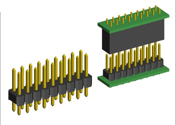
@tommas you could easily take a piece of prototyping PCB like this and create your own daughter/prototyping board if you need more space than the prototyping area has.
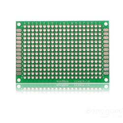
Use a set of connectors like this to connect to the MysX connector on the easy newbie board.
-
I have plans for MYSX connector daughter boards, maybe if you tell me more about what you are planning to use I can adapt.
-
Hi community!
i just got to fiddle around with my new newbie pcb and i ran into some problems.
I am already quite familiar with mysensors as i have built quite a couple of different nodes which are working very well (all on bread boards or selfmade pcb boards)
No i wanted to step up a bit and bought the newbie pcb boards.
I want to have a battery powered setup. So i did solder all the parts on the board. checked my wiring many times and also checked all components. I even did check the whole pcb board if every line is ok with a multimeter.So my problem is:
all the time i debug my node (mockup sketch) with the Arduino IDE powered by battery, stable power source etc i end up having the error TSP failed.when i leave my set up as is (i solders headers to the board to conveniently change the components ) and only power the NRF24 seperatly i get no errors. So it must be something with my power ?
but i don't get it where exactly my problem lies.
Could somebody help me? -
Hi community!
i just got to fiddle around with my new newbie pcb and i ran into some problems.
I am already quite familiar with mysensors as i have built quite a couple of different nodes which are working very well (all on bread boards or selfmade pcb boards)
No i wanted to step up a bit and bought the newbie pcb boards.
I want to have a battery powered setup. So i did solder all the parts on the board. checked my wiring many times and also checked all components. I even did check the whole pcb board if every line is ok with a multimeter.So my problem is:
all the time i debug my node (mockup sketch) with the Arduino IDE powered by battery, stable power source etc i end up having the error TSP failed.when i leave my set up as is (i solders headers to the board to conveniently change the components ) and only power the NRF24 seperatly i get no errors. So it must be something with my power ?
but i don't get it where exactly my problem lies.
Could somebody help me?@helvetian - hi, sure we can help!
But it would be much easier if you described your hardware setup (picture?) and logs.
The EasyPCB is versatile so you can use it in many ways, but a wrong combination can make it not work.
Do you use a DC-DC booster? Batteries? Which jumpters did you solder? And so on...Did you by any chance connect both batteries and ftdi Vcc at the same time?
Hello! It looks like you're interested in this conversation, but you don't have an account yet.
Getting fed up of having to scroll through the same posts each visit? When you register for an account, you'll always come back to exactly where you were before, and choose to be notified of new replies (either via email, or push notification). You'll also be able to save bookmarks and upvote posts to show your appreciation to other community members.
With your input, this post could be even better 💗
Register Login