What did you build today (Pictures) ?

-
Today I finished the coding for my prototype of a laser distance sensor (intended to measure the water level for my automatic in-door flower watering pump). The sensor is connected via I²C and has sleep pin.
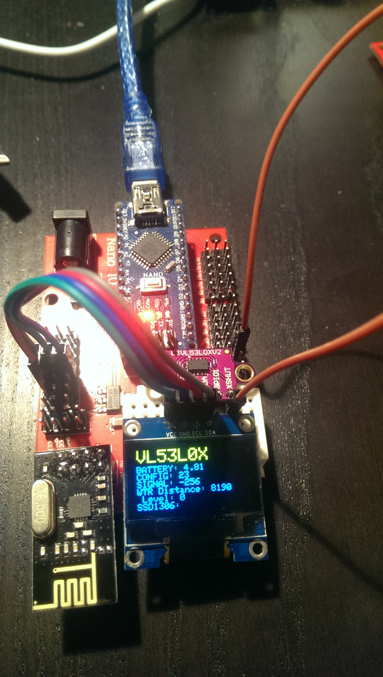
The most work was implementing support for the VL52L0X laser distance sensor and for my 128x64 OLED display to NodeManager (PRs submitted as https://github.com/mysensors/NodeManager/pull/244 and https://github.com/mysensors/NodeManager/pull/245).
The OLED is really useful when prototyping sensor nodes. Out of the box, my NodeManager OLED implemention will display the values of all attached sensors without any coding. Simply create the DisplaySSD1306 after all other sensors, and the OLED will pick up and display all sensors automatically...
Once everything works, of course the OLED is not desired for the water level sensor running on batteries...
-
Today I finished the coding for my prototype of a laser distance sensor (intended to measure the water level for my automatic in-door flower watering pump). The sensor is connected via I²C and has sleep pin.
The most work was implementing support for the VL52L0X laser distance sensor and for my 128x64 OLED display to NodeManager (PRs submitted as https://github.com/mysensors/NodeManager/pull/244 and https://github.com/mysensors/NodeManager/pull/245).
The OLED is really useful when prototyping sensor nodes. Out of the box, my NodeManager OLED implemention will display the values of all attached sensors without any coding. Simply create the DisplaySSD1306 after all other sensors, and the OLED will pick up and display all sensors automatically...
Once everything works, of course the OLED is not desired for the water level sensor running on batteries...
-
@gohan I'm using the SSD1306Ascii library, which does not use a display buffer and does not support graphics, only text. The drawback is that to prevent screen flickering, you have to manually clean each line of text to the EOL. Otherwise letters that are not overwritten by new text will not be cleared. See my PR for NodeManager how it works. With my approach, there is absolutely no screen flicker, the display updates properly and the memory requirements are minimal (the library docs say its 53 bytes)
I now have revision 1.0 of my OLED keypad posted on OpenHardware.io. My first revision of the board allows for either the 6 pin SPI or 4 pin I2C versions of the SSD1306 OLED display. The 9 button configuration allows for several different combinations of buttons depending on the needs of the user.
https://www.openhardware.io/view/546 -
I found out that the brinks solution I build some time ago could be upgraded with a nice additional feature. 'Filter detection'.
I created a cheat sheet as my device was equiped with RJ11 connector and 3 wires. I needed to convert it to RJ12 with filter detection.
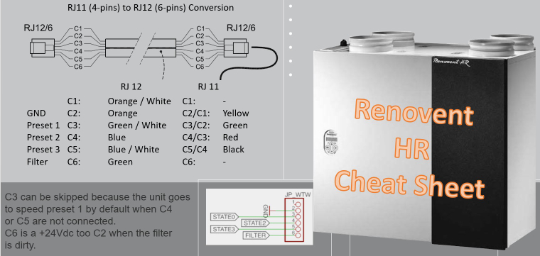
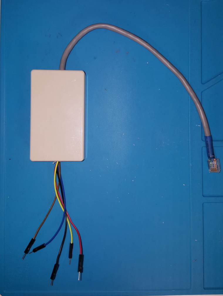
A nice black conversion box Output wires are the same colour as the original RJ 1 wire. With 2 extra wires 3,3v or 5v for the digital 'one' on the arduino.
-
@andrew said in What did you build today (Pictures) ?:
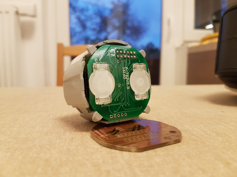
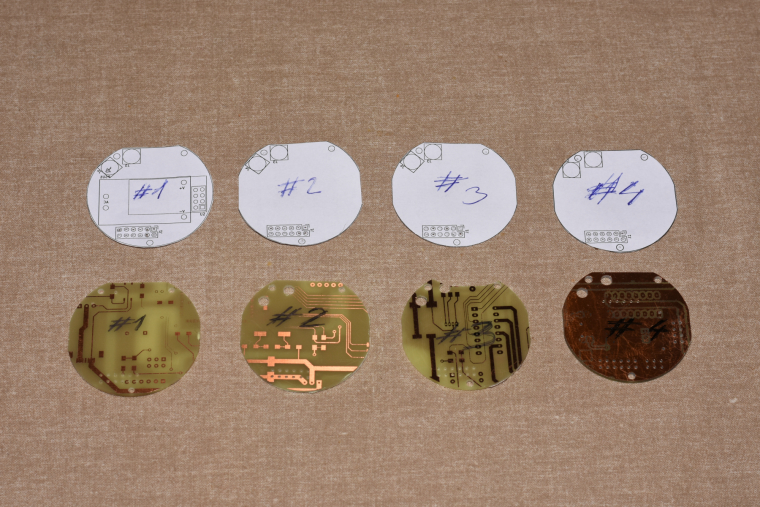
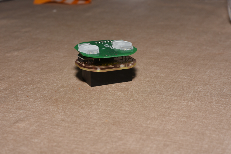
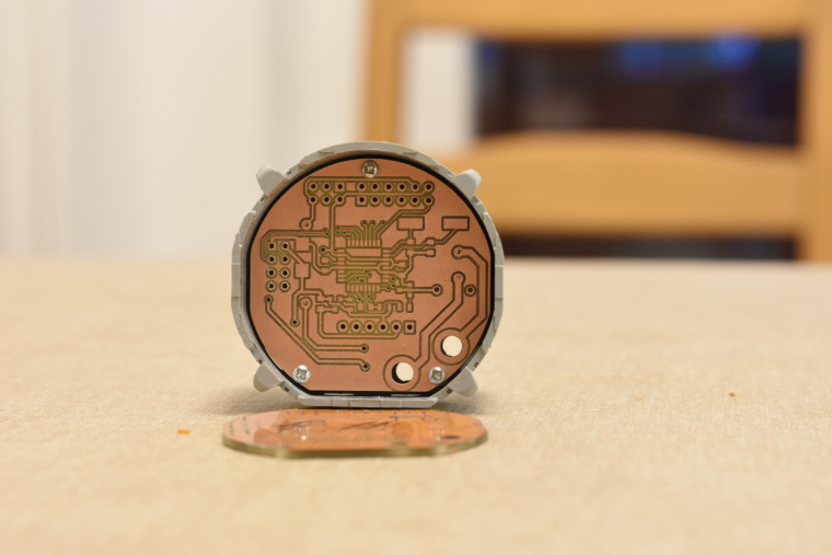
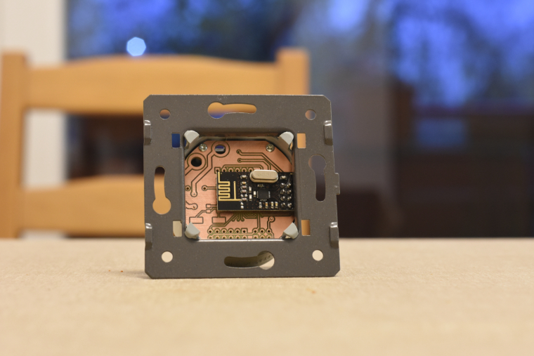
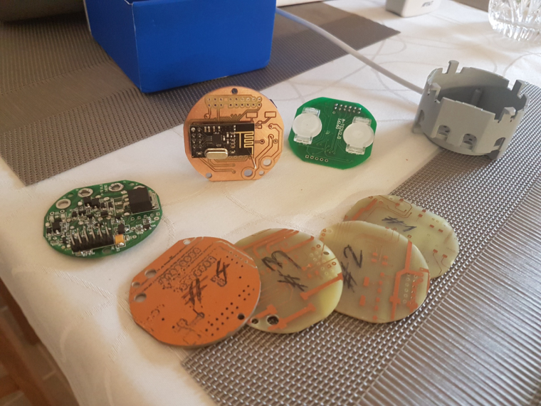
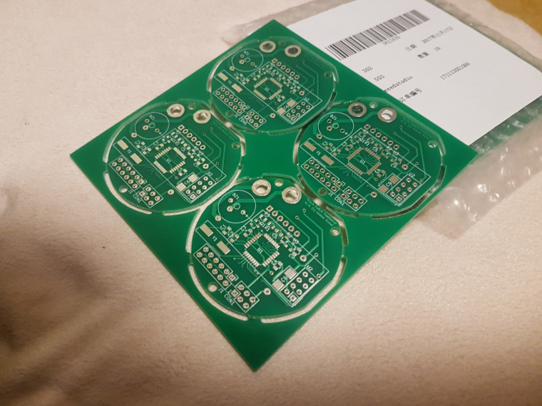
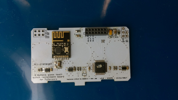
so, it is ready. I mean ready to SW development :) both the schematic and pcb design is now confirmed and fortunately theory meets the practice :)
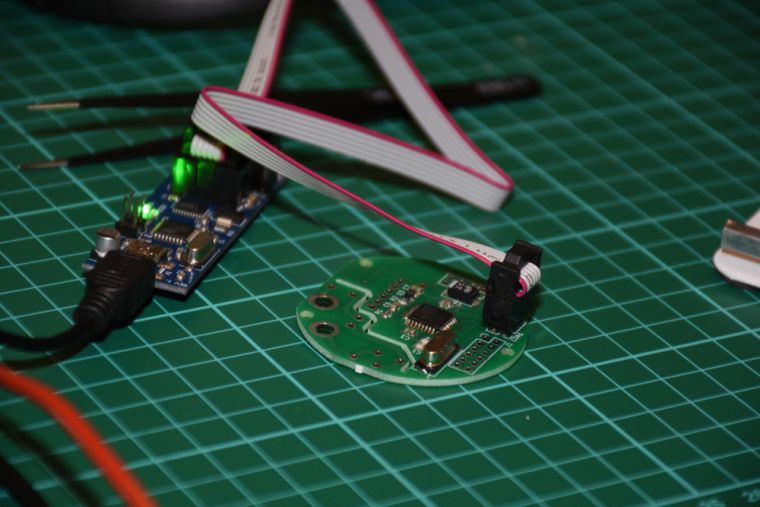
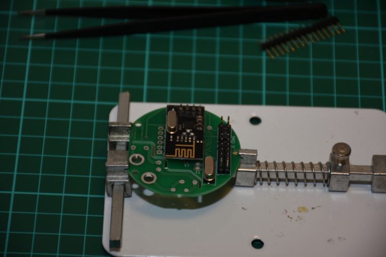
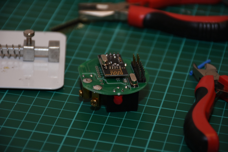
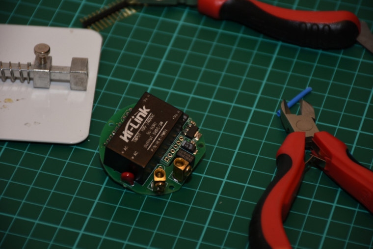
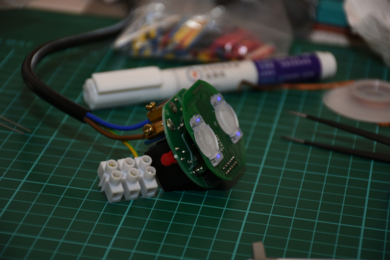
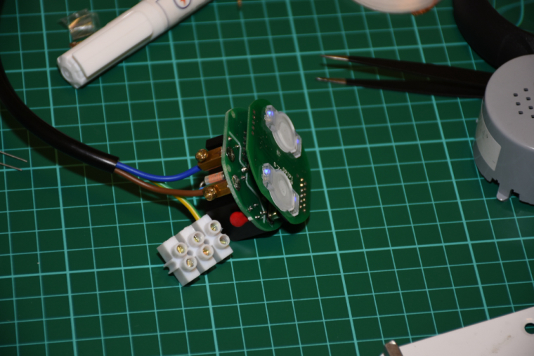
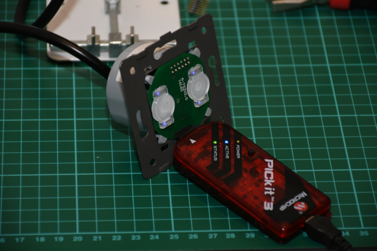
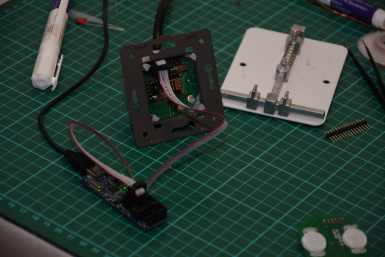
it is assembled, programmed, tested, everything works as expected.
I did not mount it to the wall so far (I'll need a controller and real actuators first), but there was no issue with the communication between two nrf modules (both with PCB antenna) from cca 6 meter distance + 2 walls (10 cm brick) in between.the touch panel's firmware will be enhanced as well as the controller's firmware, at the moment the touch sensing is reliable and a PoC code run on both of them for testing/debugging purposes. for the controller board I'm collecting additional information for the development on the following link:
https://forum.mysensors.org/topic/8831/which-sensor-and-msg-type-for-switch-dimmer-node-sender-only -
@andrew said in What did you build today (Pictures) ?:
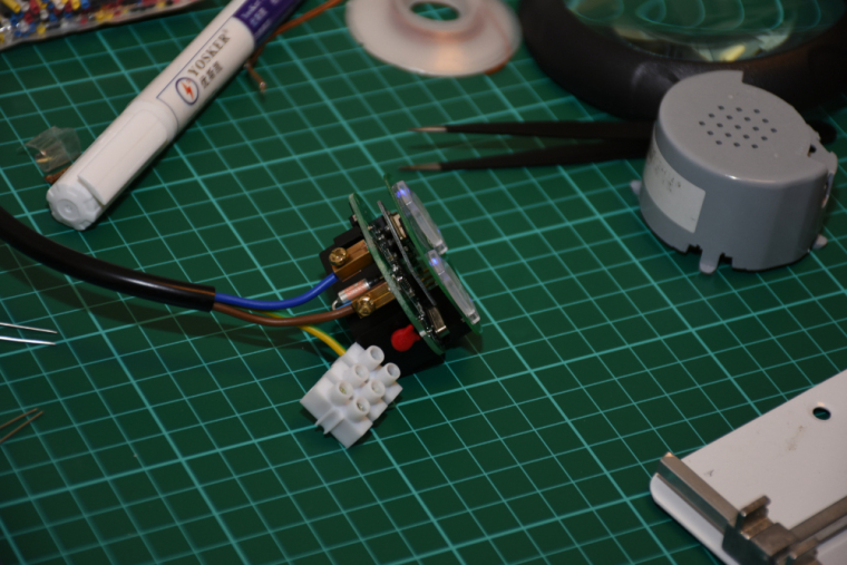
so, it is ready. I mean ready to SW development :) both the schematic and pcb design is now confirmed and fortunately theory meets the practice :)
it is assembled, programmed, tested, everything works as expected.
I did not mount it to the wall so far (I'll need a controller and real actuators first), but there was no issue with the communication between two nrf modules (both with PCB antenna) from cca 6 meter distance + 2 walls (10 cm brick) in between.the touch panel's firmware will be enhanced as well as the controller's firmware, at the moment the touch sensing is reliable and a PoC code run on both of them for testing/debugging purposes. for the controller board I'm collecting additional information for the development on the following link:
https://forum.mysensors.org/topic/8831/which-sensor-and-msg-type-for-switch-dimmer-node-sender-only -
-
-
-
Added a buzzer to my nRF51822 coincell device to make a locator beacon. Attach the device to an object you tend to lose and it will make sounds when you activate it, allowing you to find it.
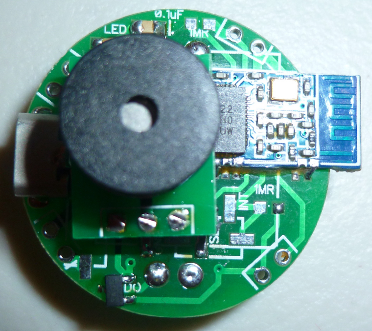
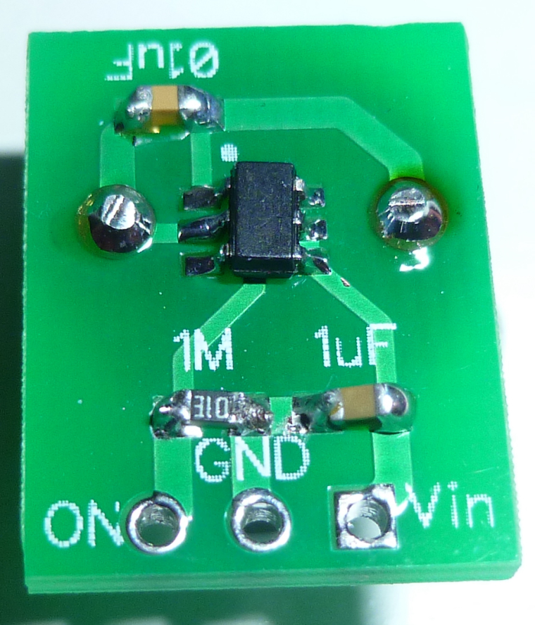
The buzzer is driven by a load switch, so that none of the nRF51822 pins are overloaded:
-
Added a buzzer to my nRF51822 coincell device to make a locator beacon. Attach the device to an object you tend to lose and it will make sounds when you activate it, allowing you to find it.
The buzzer is driven by a load switch, so that none of the nRF51822 pins are overloaded:
-
Finally, the last day of my holiday I managed to upload the Mysensors Sketch into the NodeMCU to control my 900 LEDS. It will also read the lux intensity in the livingroom. So if it is dark the lights will switch on.
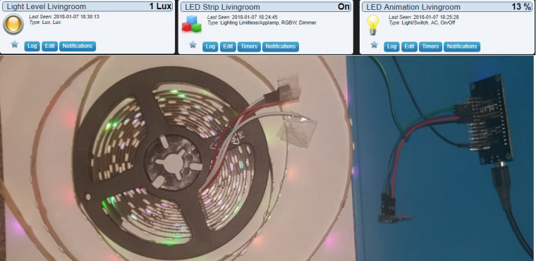
All is based on @Yveaux Mysensors ESP Gateway port. On a rainy saterday last year @Yveaux and I found out we did not have to modify anything on the voltag level for driving the LEDS. ;)
The sketch includes all the Doll_House animations (around 55) that can be skipped through using an old 433mhz remote (or via interface directly ofcourse) Next stop... Installing 15 meters of LED in the livingroom. pffff ;-)
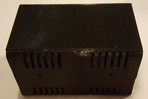
And putting everything inside this little box @Yveaux printed for me.
-
Hi,
today I've almost finished a speaker build :) (it'll be a gift for family)
First, I would like to thx Paul Carmody who created the original design of these speakers : Overnight Sensation :clap: :+1:
https://sites.google.com/site/undefinition/diy-overnightsensationsI have just changed size and format (of course I kept the internal air volume which is very important)
-
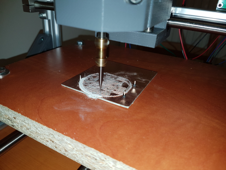
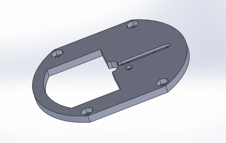
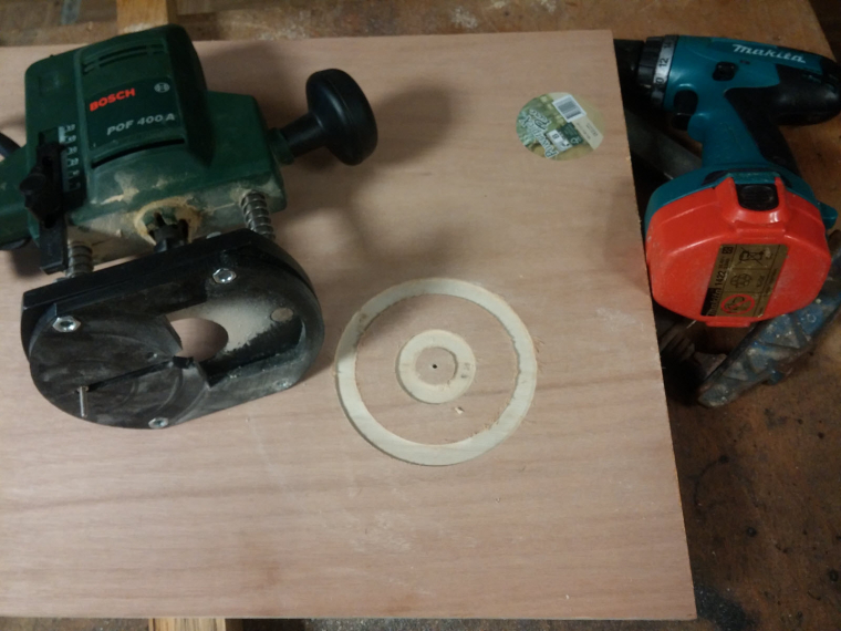
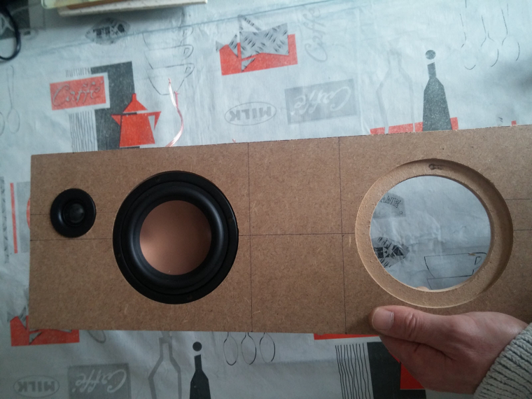
I designed&printed a simple circle jig for my router.
-
So speaker drivers can be flush on front plate
-
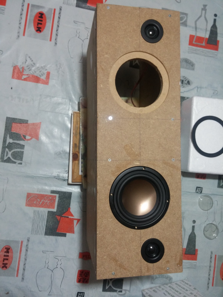
Assembled the box
-
Crossover, port tube, foam
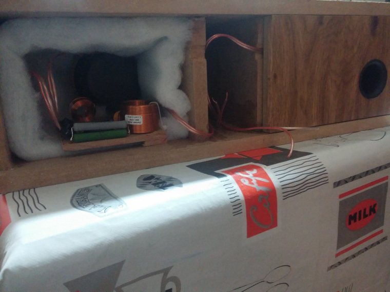
with a special place to fit some electronics like
- rpi (for Volumio/LMS client, or a voice assistant)
- cheap dac & 2x50w amp from aliexpress
- Now vinyling. I need to change these ugly black screws too.
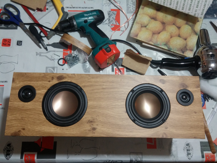
Of course, I'm too excited (and not very patient ), so I've tested how they sound... Loud! Crystal sound with very nice boomboom :muscle:
Not finished, but in good way :)
-
-
Hi,
today I've almost finished a speaker build :) (it'll be a gift for family)
First, I would like to thx Paul Carmody who created the original design of these speakers : Overnight Sensation :clap: :+1:
https://sites.google.com/site/undefinition/diy-overnightsensationsI have just changed size and format (of course I kept the internal air volume which is very important)
-
I designed&printed a simple circle jig for my router.
-
So speaker drivers can be flush on front plate
-
Assembled the box
-
Crossover, port tube, foam
with a special place to fit some electronics like
- rpi (for Volumio/LMS client, or a voice assistant)
- cheap dac & 2x50w amp from aliexpress
- Now vinyling. I need to change these ugly black screws too.
Of course, I'm too excited (and not very patient ), so I've tested how they sound... Loud! Crystal sound with very nice boomboom :muscle:
Not finished, but in good way :)
@scalz I have to guess this is a centre speaker?
Some tidy inductors there on the crossover...
How times have changed, now you can PRINT a router jig, used to make them with a piece of plywood for circles smaller that the router radius... Centre was drilled and fitted with threaded rod so you could cut back the front of the baffle but also chamfer the back face of the speaker baffle before cutting out the opening...
Tidy enough, great when they get fired up.... -
-
Today I (finally) finished a full working version of that old Livolo 3 buttons switch. I removed the RGB led on the central button as it's not visible, but the basic switch functionality with buttons/relays and blue/red status leds runs fine.
It's running with MYSBootloader, it's really convenient to update without having to switch of the fuse and unmount everything.
A (quick) video, touch sensibility is perfect now, I'm really happy with it !
https://www.youtube.com/watch?v=G6yEdSyoMYw -
Hi,
today I've almost finished a speaker build :) (it'll be a gift for family)
First, I would like to thx Paul Carmody who created the original design of these speakers : Overnight Sensation :clap: :+1:
https://sites.google.com/site/undefinition/diy-overnightsensationsI have just changed size and format (of course I kept the internal air volume which is very important)
-
I designed&printed a simple circle jig for my router.
-
So speaker drivers can be flush on front plate
-
Assembled the box
-
Crossover, port tube, foam
with a special place to fit some electronics like
- rpi (for Volumio/LMS client, or a voice assistant)
- cheap dac & 2x50w amp from aliexpress
- Now vinyling. I need to change these ugly black screws too.
Of course, I'm too excited (and not very patient ), so I've tested how they sound... Loud! Crystal sound with very nice boomboom :muscle:
Not finished, but in good way :)
-
Hello! It looks like you're interested in this conversation, but you don't have an account yet.
Getting fed up of having to scroll through the same posts each visit? When you register for an account, you'll always come back to exactly where you were before, and choose to be notified of new replies (either via email, or push notification). You'll also be able to save bookmarks and upvote posts to show your appreciation to other community members.
With your input, this post could be even better 💗
Register Login