SCT-013-050 measuring current and appearance power
-
Hi, i am trying to measure current and appearance power via SCT-013-050. Used diagram is below.
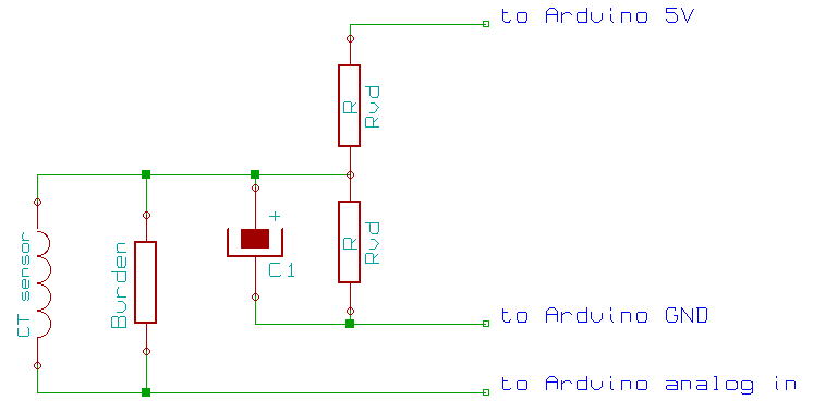
I used this without a burden because SCT-013-050 has a build in one(am i wrong?). Capacitor is 100uF. Resistors are 22k. Used sketch is below.
#include "EmonLib.h"                   // Include Emon Library
EnergyMonitor emon1;                   // Create an instance

void setup()
{
  Serial.begin(9600);

  emon1.current(A0, 50);             // Current: input pin, calibration.
}

void loop()
{
  double Irms = emon1.calcIrms(1480);  // Calculate Irms only

  Serial.print(Irms*230.0);	       // Apparent power
  Serial.print(" ");
  Serial.println(Irms);		       // Irms
}
I am using NodeMCU and sending sensor value to iot hub. Measured sensor value is not stable and depends on power source. If i use a usb sockets on my mac, sensor value transformed in appearance(value*230) is around 80-120(I am measuring current of mac pro) but if i use an charging usb adaptor to power NodeMCU the sensor value is around 500-650.
Tried to disconnect SCT-013-050 from power cable the sensor value is nearly zero on mac's usb power supply. It seems correctly working. Disconnected sensor value via usb adaptor is nearly 500 (appearance power).
I am really stucked. How to solve this problem?
-
Hi guys, i really need a help. Anyone?
-
Yes, actually i plan to measure the coffe machine's current.
-
Yes, actually i plan to measure the coffe machine's current.
-
If you plan measure current only and not real power at every ms, cos fi ( power factor )etc., I suggest convert signal from CT into DC voltage and normally measure it by ADC.
-
From the website the SCT-013-050 outputs 0 to 1 volt for a current of 0 to 50 amps.
I agree the "burden" resistor is built in on this module.
Please verify you are only passing one of the coffeemaker wires through the sensor. If you pass the whole cable through the sensor you will get no output voltage from the sensor.
A typical coffee maker requires ~1000 watts. At 230 vac this is ~4 amps. So the output of the current sensor should be about +/- 4/50*1 = 0.08 volts. This means the arduino has to measure readings from 0 to about 0.11 volts then calculate the RMS. doable but the readings are getting somewhat small to be stable.
I would suggest:
-
measure the sensor output with a multimeter if you have one.
-
Change the reference of A/D converter on the Arduino from the default to the 1.1V internal reference. Not sure the code but you should be able to find it easy enough.
-
you can increase the output of the sensor by passing the coffee maker wire through multiple times. For each time the wire goes through the sensor the sensitivity is increased by that number.
for example if you pass the wire through the sensor 3 times. The output becomes 0 to 1 volt for 0 to 50/3 amps . -
Add a 0.1µF Capacitor across the sensor (where the burden resistor is shown on your diagram. This will remove some of the noise that exists on all AC lines.
-
Hello! It looks like you're interested in this conversation, but you don't have an account yet.
Getting fed up of having to scroll through the same posts each visit? When you register for an account, you'll always come back to exactly where you were before, and choose to be notified of new replies (either via email, or push notification). You'll also be able to save bookmarks and upvote posts to show your appreciation to other community members.
With your input, this post could be even better 💗
Register Login