💬 Button size radionode with sensors swarm extension
-
But please share a list element what capacity and resistor and other and with what body. Ex 0805 etc.
But for programming i dont need push/wire RST with GND ?
Explaine me how works Programming is activated via DTR pin automatically ??
And what is ButtonSizeNode_V2 (with dc-dc) ?? What is diffrent to v1 ?
@pepson said in 💬 Button size radionode with sensors swarm extension:
But for programming i dont need push/wire RST with GND ?
Explaine me how works Programming is activated via DTR pin automatically ??
No, no need to connect RST with GND.
DTR works automatically - as soon as you press upload in your Arduino IDE, it starts uploading the sketch to the atmega328p. Simple -
@pepson said in 💬 Button size radionode with sensors swarm extension:
And what is ButtonSizeNode_V2 (with dc-dc) ?? What is diffrent to v1 ?
https://github.com/EasySensors/ButtonSizeNode
https://github.com/EasySensors/ButtonSizeNode2@pepson said in 💬 Button size radionode with sensors swarm extension:
But please share a list element what capacity and resistor and other and with what body. Ex 0805 etc.
Will try to share soon. Almost all elements are 0402.
-
Ok please share list components... i wait for it.
And diffrent with v1 and v2 is only that v2 have two batteries ? -
Hi
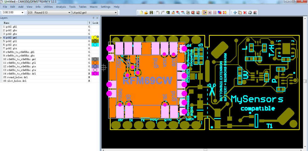
Can you share your project file and file gerber with this specification
https://support.jlcpcb.com/article/44-how-to-export-kicad-pcb-to-gerber-filesOr can you put description to also file gerber ?
Thanks -
@pepson said in 💬 Button size radionode with sensors swarm extension:
Failed load project to production.
You mixed gerbers of the main board and adapter board.
@pepson said in 💬 Button size radionode with sensors swarm extension:
Please share also layer describe...
It is standard. If you really need it you can find layers description here
https://goo.gl/Jv33Lb (Generated Gerber Files)@pepson said in 💬 Button size radionode with sensors swarm extension:
Can you share your project file and file gerber with this specification
No I can't. Have no time today, sorry.
-
@pepson said in 💬 Button size radionode with sensors swarm extension:
Failed load project to production.
You mixed gerbers of the main board and adapter board.
@pepson said in 💬 Button size radionode with sensors swarm extension:
Please share also layer describe...
It is standard. If you really need it you can find layers description here
https://goo.gl/Jv33Lb (Generated Gerber Files)@pepson said in 💬 Button size radionode with sensors swarm extension:
Can you share your project file and file gerber with this specification
No I can't. Have no time today, sorry.
-
@koresh said in 💬 Button size radionode with sensors swarm extension:
You mixed gerbers of the main board and adapter board.
Can you explaine me more ? What can i do ?
-
Hi @koresh I'm having problems with battery monitor. Trying to find out what's wrong, I have realiced that A6 analog reads from regulator output. So It allways reports 3,3V, isn't it?
Also, I read that unregulated could go up to 6,5V. Wouldn't this destroy radio module? I think I'm missing something.
Thanks.
-
@Koresh I still have a bunch of v1 boards that I never got to work because of power consumption (I presume). I thought I'd make one more attempt.
I tried bridging the jumper and I'm using a 2032 battery. Consumption varies between 2 and 4mA on different boards. On some boards it fluctuates a lot. The instructions above are not immediately clear. Do I have to remove the LDO AND capacitors as well?
-
while measuring current draw , was there FDTI adapter connected also?
Hello! It looks like you're interested in this conversation, but you don't have an account yet.
Getting fed up of having to scroll through the same posts each visit? When you register for an account, you'll always come back to exactly where you were before, and choose to be notified of new replies (either via email, or push notification). You'll also be able to save bookmarks and upvote posts to show your appreciation to other community members.
With your input, this post could be even better 💗
Register Login