Multiple switch inputs
-
Hello all,
I'm new here and also new to MySensors. I got here trough Domoticz.
At the moment I have an Arduino Nano running and configured as a serial gateway trough USB.
I've combined the relay and temperature sketch and now I can use a ds18b20 and 8 relays simultaneous on that board.But I want to add some switches too. I've seen a button sketch but that is for just one button.
I've read about expanding this sketch would give problems with the debounce code.Does anyone have an example for multiple switches on one Arduino?
Thanks in advance!
-
IMHO this is a good starting point: https://forum.mysensors.org/topic/4847/multi-button-relay-sketch/33
-
Well to make three inputs I've come to this using the code you mentioned...
I've removed the invert function because I could get Domotics invert the
monitoring. And I've added an initial read at startup. Because at powering-up
the switches were not read. Any comments? Regards!// Enable debug prints to serial monitor #define MY_DEBUG // Enable serial gateway #define MY_GATEWAY_SERIAL #include <SPI.h> #include <MySensors.h> #include <Bounce2.h> // Define Sensor ID's #define KNOB_A_ID 1 // Id of the sensor child #define KNOB_B_ID 2 // Id of the sensor child #define KNOB_C_ID 3 // Id of the sensor child // Define buttons const int buttonPinA = 10; const int buttonPinB = 11; const int buttonPinC = 12; // Define Variables int oldValueA = 0; int oldValueB = 0; int oldValueC = 0; bool stateA = false; bool stateB = false; bool stateC = false; int trigger = 0; Bounce debouncerA = Bounce(); Bounce debouncerB = Bounce(); Bounce debouncerC = Bounce(); MyMessage msgA(KNOB_A_ID, V_STATUS); MyMessage msgB(KNOB_B_ID, V_STATUS); MyMessage msgC(KNOB_C_ID, V_STATUS); void setup() { pinMode(buttonPinA, INPUT_PULLUP); // Setup the button Activate internal pull-up pinMode(buttonPinB, INPUT_PULLUP); // Setup the button Activate internal pull-up pinMode(buttonPinC, INPUT_PULLUP); // Setup the button Activate internal pull-up // After setting up the buttons, setup debouncer debouncerA.attach(buttonPinA); debouncerA.interval(5); debouncerB.attach(buttonPinB); debouncerB.interval(5); debouncerC.attach(buttonPinC); debouncerC.interval(5); /*--------------------- Added these lines for toggle switch-------------------------*/ oldValueA = digitalRead(buttonPinA); // set oldValueA to the current status of the toggle switch oldValueB = digitalRead(buttonPinB); // set oldValueB to the current status of the toggle switch oldValueC = digitalRead(buttonPinC); // set oldValueC to the current status of the toggle switch } void presentation() { // Send the sketch version information to the gateway and Controller sendSketchInfo("2x bistable button", "1.1"); // Register all sensors to gw (they will be created as child devices) present(KNOB_A_ID, S_LIGHT); present(KNOB_B_ID, S_LIGHT); present(KNOB_C_ID, S_LIGHT); } void loop() { if (trigger == 0) { debouncerA.update(); // Get the startup valueA int valueA = debouncerA.read(); send(msgA.set(valueA==HIGH ? 0 : 1)); debouncerB.update(); // Get the startup valueB int valueB = debouncerB.read(); send(msgB.set(valueB==HIGH ? 0 : 1)); debouncerC.update(); // Get the startup valueC int valueC = debouncerC.read(); send(msgC.set(valueC==HIGH ? 0 : 1)); trigger = 1; } debouncerA.update(); // Get the update valueA int valueA = debouncerA.read(); if (valueA != oldValueA) { // Send in the new valueA send(msgA.set(valueA==HIGH ? 0 : 1)); oldValueA = valueA; } debouncerB.update(); // Get the update valueB int valueB = debouncerB.read(); if (valueB != oldValueB) { // Send in the new valueB send(msgB.set(valueB==HIGH ? 0 : 1)); oldValueB = valueB; } debouncerC.update(); // Get the update valueC int valueC = debouncerC.read(); if (valueC != oldValueC) { // Send in the new valueC send(msgC.set(valueC==HIGH ? 0 : 1)); oldValueC = valueC; } } -
Seems to be a good starting point, but some remarks:
- Using PINs 10-12 might not be the best choice in case you want to add a radio later (my code was for RS485@HWSerial)
- Doing this kind of task using arrays gives much more flexibility and easier reading imho
So essential Part of the sketch could be reduced to something like (untested, changing PINs recommended):
... #include <Bounce2.h> #define FIRST_PIR_ID 1 #define MAX_PIRS 3 const uint8_t pirPin[] = {10, 11,12}; // switch around pins to your desire Bounce debouncer[MAX_PIRS]; MyMessage pirMsg(0, V_TRIPPED); bool oldPir[MAX_PIRS] = {false}; void before() { } void presentation() { // Send the sketch version information to the gateway and Controller sendSketchInfo(SN, SV); // Fetch the number of attached temperature sensors for (int i = 0; i < MAX_PIRS; i++) { //i < numSensors && present(FIRST_PIR_ID + i, S_MOTION); } } void setup() { for (uint8_t i = 0; i < MAX_PIRS; i++) { debouncer[i] = Bounce(); // initialize debouncer debouncer[i].attach(pirPin[i], INPUT_PULLUP); debouncer[i].interval(5); oldPir[i] = debouncer[i].read(); } } void loop() { bool pir[MAX_PIRS]; for (uint8_t i = 0; i < MAX_PIRS; i++) { debouncer[i].update(); pir[i] = debouncer[i].read(); if (pir[i] != oldPir[i]) { send(pirMsg.setSensor(FIRST_PIR_ID + i).set( pir[i])); // Send tripped value to gw oldPir[i] = pir[i]; } } }``` -
Thanks for the comment, I will look at it.
Another question, the inputs look exactly like an output in domoticz.
I can even switch on the lamp with the mouse. Of course there is nothing happening
because it is an input. But it is a bit confusing. Is this a Domoticz setting? Or can I change
something in the MySensors code for this? Thanks!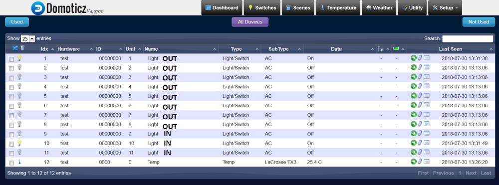
-
Thanks for the comment, I will look at it.
Another question, the inputs look exactly like an output in domoticz.
I can even switch on the lamp with the mouse. Of course there is nothing happening
because it is an input. But it is a bit confusing. Is this a Domoticz setting? Or can I change
something in the MySensors code for this? Thanks!@pdp8 Despite not beeing familiar with domoticz, this behaviour seems to be logic to me: You presentet a light device, so this typiclly is switchable from controller side.
You might either change the handling within domiticz or present a different Child Type (my code uses motion). -
Hmm, I've changed it to S_DOOR now. But I still can turn it on and off in Domoticz.
I guess this is a Domoticz thing and has nothing to do with MySensors... Weird...@pdp8 By default Domoticz will add a S_BINARY, S_DOOR, S_MOTION and S_DIMMER (and likely a few others) device in the form of a switchable lamp. You can add it to the active devices and then change the type to be a different device.
For example when you create a S_MOTION device, it initially gets added as a lamp in Domoticz, but then you can later change the switch type to be a motion sensor. This changes the icon displayed in Domoticz and also stops you from changing the state.
Hello! It looks like you're interested in this conversation, but you don't have an account yet.
Getting fed up of having to scroll through the same posts each visit? When you register for an account, you'll always come back to exactly where you were before, and choose to be notified of new replies (either via email, or push notification). You'll also be able to save bookmarks and upvote posts to show your appreciation to other community members.
With your input, this post could be even better 💗
Register Login