Radio setup give: "check wires"
-
@Squint I have problem with Ack and I have assumed that it has to do with the non + . I have a + variant on my gateway but non puls on my sensor node.
@olaeke I believe this is how I have mine setup as well.. Oddly enough both modules have the "+" printed on the chip but I cannot get the sensor code to initialize unless i take out the PVariant check. printDetails shows the following:
Gateway:
Data Rate = 2MBPS
Model = nRF24L01+Sensor:
STATUS = 0x00 RX_DR=0 TX_DS=0 MAX_RT=0 RX_P_NO=0 TX_FULL=0
RX_ADDR_P0-1 x00 = 0x0000000000 0x0000000000
RX_ADDR_P2-5 x00 = 0x00 0x00 0x00 0x00
TX_ADDR = 0x0000000000
RX_PW_P0-6 x00 = 0x00 0x00 0x00 0x00 0x00 0x00
EN_AA = 0x00
EN_RXADDR x00 = 0x00
RF_CH = 0x00
RF_SETUP x00 = 0x00
CONFIG = 0x00
DYNPD/FEATURE x00 = 0x00 0x00
Data Rate = 1MBPS
Model = nRF24L01
CRC Length = Disabled
PA Power = PA_MINThe odd part is, on the sensor - all of the values in printDetails(); are 0's.. So I suspect I have something wired incorrectly?
I've double & tripple checked the wiring..Thanks.
-
@olaeke I believe this is how I have mine setup as well.. Oddly enough both modules have the "+" printed on the chip but I cannot get the sensor code to initialize unless i take out the PVariant check. printDetails shows the following:
Gateway:
Data Rate = 2MBPS
Model = nRF24L01+Sensor:
STATUS = 0x00 RX_DR=0 TX_DS=0 MAX_RT=0 RX_P_NO=0 TX_FULL=0
RX_ADDR_P0-1 x00 = 0x0000000000 0x0000000000
RX_ADDR_P2-5 x00 = 0x00 0x00 0x00 0x00
TX_ADDR = 0x0000000000
RX_PW_P0-6 x00 = 0x00 0x00 0x00 0x00 0x00 0x00
EN_AA = 0x00
EN_RXADDR x00 = 0x00
RF_CH = 0x00
RF_SETUP x00 = 0x00
CONFIG = 0x00
DYNPD/FEATURE x00 = 0x00 0x00
Data Rate = 1MBPS
Model = nRF24L01
CRC Length = Disabled
PA Power = PA_MINThe odd part is, on the sensor - all of the values in printDetails(); are 0's.. So I suspect I have something wired incorrectly?
I've double & tripple checked the wiring..Thanks.
@Squint That seem even more tricky that the have printed + on the chip and then it still is non plus.
I really don't remember now if I run the getstatus() on the sensor node or it was only on the gateway, but it sound strange that you get zeros on all information. The only thing I can think of is either is the radio broken or is there som more #define in the code you have to comment out the get the status info to print correctly.
I will also remember that I had to fix some more issue in the code to get the non plus to work, I think a made a hack in the process method in the MySensor class, and still the acknowledge didn't work. But I'm not totally shure, I have had a lot of problem with my sensors and my Vera Edge.
Yesterday I received my new radios (yes + variant) and my Ethernet shield. I have now replaced my radios, replaced the serial gateway with Ethernet (the serial port is not working on Vera Egde, good work Mi Casa Verde!) replaced all my hacked library code with fresh from MySensors.org and...
NOW IT WORKS!
I will take the old non plus radio and burn them in the garden tomorrow!
FYI as sonicblaze wrote is Alice breaking point to give them bad feedback then they contact you within a week and offer you refund,.
-
@Squint That seem even more tricky that the have printed + on the chip and then it still is non plus.
I really don't remember now if I run the getstatus() on the sensor node or it was only on the gateway, but it sound strange that you get zeros on all information. The only thing I can think of is either is the radio broken or is there som more #define in the code you have to comment out the get the status info to print correctly.
I will also remember that I had to fix some more issue in the code to get the non plus to work, I think a made a hack in the process method in the MySensor class, and still the acknowledge didn't work. But I'm not totally shure, I have had a lot of problem with my sensors and my Vera Edge.
Yesterday I received my new radios (yes + variant) and my Ethernet shield. I have now replaced my radios, replaced the serial gateway with Ethernet (the serial port is not working on Vera Egde, good work Mi Casa Verde!) replaced all my hacked library code with fresh from MySensors.org and...
NOW IT WORKS!
I will take the old non plus radio and burn them in the garden tomorrow!
FYI as sonicblaze wrote is Alice breaking point to give them bad feedback then they contact you within a week and offer you refund,.
@olaeke It turns out mine were actually + models. I had the sensors wired incorrectly because I had SOFTSPI enabled.. Once I realized the correct pinout ( After about 3 days of trial/error/code-digging ) its now reporting the + as it should and the radios are working as intended.
Thanks!
-
I have modified the excelent "ping/pong test" program from maniacbug so it compiles with the RF24 lib. that comes with MySensors 1.4
With this program it is very easy to test your radio if it works or maybe if it works bad (many timeouts) and you also get this info printed if it is a + or non + chip.
- Download attached zip
- Build ino file
- Uppload on two nodes
- Connect serial monitor (115200 baud)
- Press T in serial monitor and then you should se "
Now sending 29788...ok...Got response 29788, round-trip delay: 23"
For the printout of chip details you need to comment out #define MINIMAL in RF24_config.h. I also recommend comment SERIAL_DEBUG so you get less debuginfo on serial.
MySensorsPingPongTst.zip -
I have modified the excelent "ping/pong test" program from maniacbug so it compiles with the RF24 lib. that comes with MySensors 1.4
With this program it is very easy to test your radio if it works or maybe if it works bad (many timeouts) and you also get this info printed if it is a + or non + chip.
- Download attached zip
- Build ino file
- Uppload on two nodes
- Connect serial monitor (115200 baud)
- Press T in serial monitor and then you should se "
Now sending 29788...ok...Got response 29788, round-trip delay: 23"
For the printout of chip details you need to comment out #define MINIMAL in RF24_config.h. I also recommend comment SERIAL_DEBUG so you get less debuginfo on serial.
MySensorsPingPongTst.zipI can not get it to work.
The pins I use on nRF24L01 + / nRF24L01
Arduino NRF24L01 Radio Ethernet module
GND GND
3.3V VCC
13 SCK
12 MISO
11 MOSI
6 CSN
5 CEAnd what I get is this
STATUS = 0x00 RX_DR=0 TX_DS=0 MAX_RT=0 RX_P_NO=0 TX_FULL=0
RX_ADDR_P0-1 = 0x0000000000 0x0000000000
RX_ADDR_P2-5 = 0x00 0x00 0x00 0x00
TX_ADDR = 0x0000000000
RX_PW_P0-6 = 0x00 0x00 0x00 0x00 0x00 0x00
EN_AA = 0x00
EN_RXADDR = 0x00
RF_CH = 0x00
RF_SETUP = 0x00
CONFIG = 0x00
DYNPD/FEATURE = 0x00 0x00
Data Rate = 1MBPS
Model = nRF24L01
CRC Length = Disabled
PA Power = PA_MINWhat am I doing wrong?
-
I can not get it to work.
The pins I use on nRF24L01 + / nRF24L01
Arduino NRF24L01 Radio Ethernet module
GND GND
3.3V VCC
13 SCK
12 MISO
11 MOSI
6 CSN
5 CEAnd what I get is this
STATUS = 0x00 RX_DR=0 TX_DS=0 MAX_RT=0 RX_P_NO=0 TX_FULL=0
RX_ADDR_P0-1 = 0x0000000000 0x0000000000
RX_ADDR_P2-5 = 0x00 0x00 0x00 0x00
TX_ADDR = 0x0000000000
RX_PW_P0-6 = 0x00 0x00 0x00 0x00 0x00 0x00
EN_AA = 0x00
EN_RXADDR = 0x00
RF_CH = 0x00
RF_SETUP = 0x00
CONFIG = 0x00
DYNPD/FEATURE = 0x00 0x00
Data Rate = 1MBPS
Model = nRF24L01
CRC Length = Disabled
PA Power = PA_MINWhat am I doing wrong?
-
@MLs what else is connected to arduino?
i had the same result yesterday trying to build ethernet gateway using ENC based shield. I'm faced a conflict between radio and ethernet
-
Four Dallas temp sensor.
But what I am interested in is the model I have (nRF24L01 + / nRF24L01) and not to send / receive data.
-
@MLs said:
Possible, but now I wanted to read it out of the hardware to be sure.
that is easy))) check wires
-
As I wrote earlier, it is linked and I have also measured the cables to minimize errors.
-
@axillent said:
the old version is out of production for years
But they still seem to pop up. See a bit up in the thread.
@hek you knew from our conversation last night that I also got "check wires" and was ready to think that all my modules are the old ones
but finally my issue has nothing to do with version of the chip. It is exactly "check wires" issue and issue of the conflicts with other staff,
and my modules were purchased about two years agois it any confirmed case with the old version?
-
@hek you are right
but it seams that only @sonicblaze is owner of this rare thing -
@axillent And me! I started the thread so I have got 10 of the them, maybe something for the MySensors museum!
@olaeke said:
@axillent And me! I started the thread so I have got 10 of the them, maybe something for the MySensors museum!
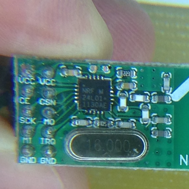
hm. are the + is missing on top of the nordic chip?
it can be probably still used for mysensors in case of:
- switching data rate to 1Mbs or 2MBs (old version do not support 250Kbs - default to 1.4)
- comment out "check wires" check inside Mysensors library
Hello! It looks like you're interested in this conversation, but you don't have an account yet.
Getting fed up of having to scroll through the same posts each visit? When you register for an account, you'll always come back to exactly where you were before, and choose to be notified of new replies (either via email, or push notification). You'll also be able to save bookmarks and upvote posts to show your appreciation to other community members.
With your input, this post could be even better 💗
Register Login